THE MOST COMMON GEOMETRIC AND SEMANTIC ERRORS IN CITYGML
DATASETS
F. Biljeckia,∗, H. Ledouxa,∗, X. Dua, J. Stotera, K. H. Soonb, V. H. S. Khoob a
3D Geoinformation, Delft University of Technology, Delft, The Netherlands — (f.biljecki, h.ledoux, x.du-2, j.e.stoter)@tudelft.nl bSingapore Land Authority, Singapore — (soon kean huat, victor khoo)@sla.gov.sg
KEY WORDS:CityGML, 3D city models, Quality control, Validation, Error
ABSTRACT:
To be used as input in most simulation and modelling software, 3D city models should be geometrically and topologically valid, and semantically rich. We investigate in this paper what is the quality of currently available CityGML datasets, i.e. we validate the geometry/topology of the 3D primitives (SolidandMultiSurface), and we validate whether the semantics of the boundary surfaces of buildings is correct or not. We have analysed all the CityGML datasets we could find, both from portals of cities and on different websites, plus a few that were made available to us. We have thus validated 40M surfaces in 16M 3D primitives and 3.6M buildings found in 37 CityGML datasets originating from 9 countries, and produced by several companies with diverse software and acquisition techniques. The results indicate that CityGML datasets without errors are rare, and those that are nearly valid are mostly simple LOD1 models. We report on the most common errors we have found, and analyse them. One main observation is that many of these errors could be automatically fixed or prevented with simple modifications to the modelling software. Our principal aim is to highlight the most common errors so that these are not repeated in the future. We hope that our paper and the open-source software we have developed will help raise awareness for data quality among data providers and 3D GIS software producers.
1. INTRODUCTION
In recent years, several cities around the world have released their 3D city models (3DCMs) as open datasets, and until recently they have been used mostly for visualisation. Such datasets are now being increasingly used as input for many different applica-tions (Biljecki et al., 2015c). For example, they can help to as-sess the impact that environmental factors, such as noise (Stoter et al., 2008), wind (Janssen et al., 2013), and temperature (Lee et al., 2013; Hsieh et al., 2011), have on the citizens. Along with their increasing usage for spatial analyses, the topic of their qual-ity and consistency has attracted attention, as several researchers started to recognise the importance of their validity (Agugiaro, 2016; Bruse et al., 2015).
In general, to be used for advanced applications, 3DCMs need: (1) that their geometries are free of errors such as part of a roof missing, a bridge not connected to the shore, two houses slightly overlapping, houses “floating” a few centimetres above the ground, etc.; (2) to have rich semantic information. However, as several have observed (Steuer et al., 2015; Alam et al., 2014; Mulder, 2015; Stadler and Kolbe, 2007; P´edrinis et al., 2015), 3DCMs are often plagued with errors and they do not always contain seman-tics, which, as a result, can have consequences because most sim-ulation and analysis software assume that the input is valid (Mc-Kenney, 1998).
The consistency of 3D city models has recently been increasingly investigated, and the OGC Quality Interoperability Experiment has been launched as solely devoted to this issue in CityGML models (OGC, 2016). Four aspects of data quality were stud-ied and multiple software packages were developed to (partially) validate the following aspects: (1) schema conformance; (2) ge-ometry (with a focus on solids); (3) semantics (with a focus on buildings); (4) conformance requirements (translation of require-ments stated in natural language into verifiable functions).
∗Corresponding authors. These authors contributed equally.
Related work considers additional aspects, e.g. resolvability of
XLinks; application-specific rules, such as that a building is re-quired to have a ground floor to form a volume (which is, surpris-ingly, not mandatory in CityGML); and the redundancy of the dataset, i.e. multiple identical geometries which are not re-used (van Walstijn, 2015; Biljecki et al., 2015b).
When inconsistencies are found, the only solution at this moment is to spend a substantial amount of hoursmanuallyrepairing the data. There are ongoing efforts to automatically repair 3D mod-els, see for instance Zhao et al. (2013), Alam et al. (2014) and Zhao et al. (2014). However, these only repair specific problems and have not been shown to be able to repair satisfactorily com-plex cases.
Since validation of 3D GIS datasets is a relatively new topic, there has not been a large-scale validation study on the current status of the quality of 3D city models. In this paper we bridge this gap, and attempt to answer a simple question: what is the geomet-ric and semantic quality of the 3DCMs stored in CityGML, and what are the most common errors they contain? In Section 2 and Section 3 we elaborate on the validation method, and we validate all the 3DCMs we could obtain, both from portals of cities and on different websites, plus a few that were made available to us. We have validated 37 datasets from different sources and of dif-ferent lineage, containing numerous buildings/features. Because buildings are the most prominent thematic feature of 3DCMs, we focus on them. However, most of the developed methodology is applicable to other thematic features as well. The quality of each is assessed by focusing on a subset of the aforementioned as-pects (those that can be assessed and for which there are reliable tools/implementations):
2. Validation of the semantic information, if any, attached to the surfaces of the buildings in the 3DCMs. We explain our methodology in Section 3.
3. Schema validation, i.e. is the XML of the files valid against the schema of CityGML? For the purpose of this paper, we consider this a “solved problem” that needs no further ex-planation since several tools exists.
In Section 4, we present, discuss, and analyse the errors we found and try to explain their source. Based on our experiments, we make in Section 5 recommendations that practitioners and data producers can follow when constructing 3DCMs. It should be pointed out that the purpose of this paper is not to shame the data producers, some of the models we validate date back to several years and producing error-free models was certainly not a prior-ity. We aim at highlighting the most common errors that exist in 3DCMs, so that these are not repeated in the future, and we hope that our paper will help to raise awareness for 3D data qual-ity among data providers. Furthermore, the developed validation software is released as open-source software, which enables data producers to check the produced datasets with the same method-ology as used in this paper, in order to fix errors before the deliv-ery of the data, and/or to include similar workflows in modelling software.
2. VALIDATION OF THE GEOMETRY OF INDIVIDUAL FEATURES 2.1 Geometric primitives
CityGML (OGC, 2012), and GML (OGC, 2007), use the ISO19107 geometric primitives for representing the geometry of its objects (ISO, 2003): a 0D primitive is aGM Point, a 1D aGM Curve, a 2D aGM Surface, and a 3D aGM Solid. Ad-dimensional primitive is built with a set of(d−1)-dimensional primitives, e.g. aGM Solidis formed by severalGM Surfaces, which are formed of severalGM Curves, which are themselves formed of
GM Point. While the ISO19107 primitives do not need to be lin-ear or planar, i.e. curves defined by mathematical functions are allowed, CityGML uses a subset of ISO19107, with the follow-ing two restrictions: (1)GM Curvescan only belinear(thus only
LineStringsand LinearRingsare used); (2)GM Surfaces
can only beplanar(thusPolygonsare used). 2.2 Aggregates & Composites
Following ISO19107, in GML and CityGML geometric primi-tives can be combined into eitheraggregatesorcomposites. An aggregate (classgml: AbstractGeometricAggregate) is an arbitrary collection of primitives of same dimensionality that is simply used to bundle together geometries. GML (and CityGML) has classes for each dimensionality (Multi*), the most relevant one in our context isMultiSurfacethat is often used in practice to represent the geometry of a building. An aggregate does not prescribe any topological relationships between the primitives. A composite of dimension d is a collection ofd-dimensional primitives that form ad-manifold, which is a topological space that islocallylike ad-dimensional Euclidean space (Rd). The most relevant example in our context is aCompositeSurface: it is a 2-manifold, or, in other words, a surface embedded inR3
. An obvious example is the surface of the Earth, for which near to every point the surrounding area is topologically equivalent to a plane. This implies that the surfaces part of a composite are
not allowed to overlap and/or to be disjoint. Furthermore, if we store aCompositeSurfacein a data structure, each edge is guar-anteed to have a maximum of two incident surfaces, and around each vertex the incident faces form one ‘umbrella’.
(a) (b)
1mm
(c)
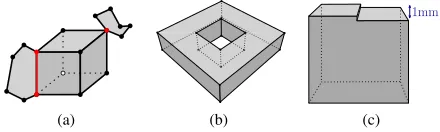
Figure 1: Some examples ofSolids. (a) An invalid one because both one edge and one vertex are non-manifold (the red ones). (b) A ‘squared torus’ is modelled with one exterior boundary formed of ten surfaces. Notice that there are no interior boundary. (c) All eight points of the top surface have theirzcoordinate within 1mm, but the polygon cannot be considered planar, and thus the solid would invalid (see Sec. 2.4).
ACompositeSurfacethat isclosed(there should not be ‘holes’
in the surface, it should be ‘watertight’) andorientableis referred to as aShell(see Figure 2). Shells are used to define the bound-aries of aSolid. In Figure 2, theSolidhas two boundaries: an exterior one (the cube in grey) and one interior one (the cube in orange), which defines a ‘void’ in the solid. ASolidcan have an infinity of interior boundaries, or none. Observe that a cavity is not the same as a hole in a torus (a donut) such as that in Fig-ure 1b: it can be represented with one exterior boundary having a genus of 1 and no interior shell. Interior boundaries in surfaces are possible, simple LOD1 buildings having for instance an inner yard require them, as Figure 1b shows.
LinearRing Polygon
Point Solid
MultiSurface CompositeSurface Shell CompositeSolid
Figure 2: Some of the CityGML primitives, including aggregates and composites. Orange primitives are those representing inner boundaries. TheShellis not a class in GML, but it is implied when aCompositeSurfaceis used to define the boundary of a
Solid.
2.3 How we validate the geometry of primitives
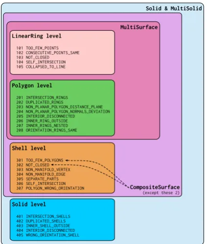
For our experiments, we used the validation methodology as de-scribed in Ledoux (2013) for solids, which is ISO19107-compli-ant. Figure 3 shows the error codes that can be reported, for dif-ferent 3D primitives. The methodology is hierarchical, i.e. a solid is validated by validating all primitives of lower-dimensionalities first, starting withLinearRings. This means that if one or more
Polygonsof aSolidis invalid, the validation process will be
Solid & MultiSolid
Figure 3: Error codes for the validation of geometric primitives. For this paper, we are focusing only on buildings. As a conse-quence: (1) interior boundaries in solids are ignored. This implies that a solid has only oneshell representing its exterior bound-ary; (2) we focus on the two representations forBuildingsin CityGML:MultiSurfacesorSolid/CompositeSolids. We validateMultiSurfaceprimitives by using a subset of the method-ology forSolids: validating an aggregate simply implies vali-dating individually each primitive in the collection. We do not explicitly validateCompositeSurface. Also, we do not validate
CompositeSolidssince we do not have access to a software
implementation that would allow us to verify the topological re-lationships between different solids. This is a shortcoming of our current result, sinceCompositeSolidsare sometimes used to represent complex buildings (e.g. with severalBuildingPart). We show examples in Section 4. However, we validateMultiSolid
primitives, if present, by validating eachSolidseparately. 2.4 Tolerances for coordinates and planarity
Geometries modelled in CityGML store amazingly very little topo-logical relationships. For instance, all six surfaces of a cube are often stored independently. This means that the coordinates (x, y, z) of a single point (where three polygons “meet”) is stored three times. It is possible that these three vertices are not ex-actly at the same location, e.g. (0.01, 0.5, 1.0), (0.011, 0.49999, 1.00004) and (0.01002, 0.5002, 1.0007), and that would create problems when validating since there would for example be tiny cracks/overlaps in the cube. We therefore use a snapping tol-erance on the input coordinates for each primitive, this value is 1mm.
While both ISO19017 and CityGML mention that eachSurface
must be planar (i.e. all its points, used for both the exterior and interior rings, must lie on a plane), the concept oftoleranceis not mentioned. We believe this is a shortcoming, and thus use two concepts that were defined during the OGC CityGML QIE (OGC, 2016):
1. the distance between every point forming a polygon and a plane is less thanǫ1, a given tolerance (e.g. 1mm). This
plane should be a plane fitted with least-square adjustment.
2. the distance between every point forming a polygon and all the planes defined by all possible combinations of 3 non-collinear points is less thanǫ1.
The second requirement is to ensure that cases such as that in Figure 1c are detected. From algorithmic point of view, the defi-nition is not very efficient, but in practice it can be implemented with a triangulation of the polygon (any triangulation): the orien-tation of the normal of each triangle must not deviate more than than a certain user-defined toleranceǫ2(e.g. 1 degree).
3. VALIDATION OF THE SEMANTICS OF BUILDINGS In CityGML, each of the surfaces used to represent a building can be a semantic class ( BoundarySurface), which defines its real-world meaning. Depending on the LOD, a BoundarySurface, can be one of nine classes. In this paper, we focus on the five possible ones for LOD2 buildings; these are shown in Figure 4.
WallSurface
Figure 4: The semantic classes for buildings that we validate, and the angles and tolerances we use.
While storing the semantic information of each surface is not mandatory, CityGML encourages it and sees it as one of its core principle, since, as Stadler and Kolbe (2007) demonstrate, it can be beneficial for several applications. As can be seen in our exper-iments, the semantics of LOD2 models is often stored in practice. While it is impossible to validate with 100% certainty the seman-tic of the surfaces of a building, we can infer it from the orien-tation of a surface. We follow the work of others (Boeters et al., 2015; Diakit´e et al., 2014; OGC, 2016), and compare the direc-tion of the normal of the surface to a reference for each class, which we have defined in Figure 4.
Because calculating the normal of a surface that is invalid (e.g. if it self-intersects, is not planar, etc.) might not be possible, for each surface we perform a linear least squares fitting (with a plane), and use the normal of that plane. Only when an invalid surface has less than 3 points we skip the normal calculation. A surface which normal is not in the range defined in Figure 4 is regarded as invalid. Observe that doors, windows and closure surfaces are not considered in this paper.
4. ANALYSIS AND RESULTS 4.1 Datasets
been obtained from open data portals of cities and universities, demo datasets from companies, and a few have been procedu-rally generated to add to the diversity. In order to focus on the discovered inconsistencies, and instead of giving an impression of blaming specific sources and producers, we do not identify the datasets in the analysis. We have merely listed the sources in the Acknowledgements.
4.2 Tools
For the validation of the geometry and semantics we have used the open-source softwareval3dity, as Ledoux (2013) describes. The schema validation was implemented in a script using Xerces, and we implemented ourselves the semantic validation. All the software is released as open-source1under a GPL licence. Hence our approach can be easily reproduced.
4.3 Used quality metrics
Since the result of a validation is binary (something is valid or not), we express errors as percentages. This is also because there is a great variation of characteristics of the datasets (some datasets contain a few buildings, while others more than one hundred thousand). However, because of the different sizes of datasets and varying structure (e.g. 20% invalid solids is not the same as 20% invalid buildings; this is later explained in Figure 6), we focus on expressing the errors on the most granular level: per-centage of valid primitives for geometry, and perper-centage of valid surfaces when it comes to the semantics. For the schema valida-tion, we state whether the files (sometimes several files are used for a given city) are valid against the schema; we have noticed that in multi-file datasets either all the files are valid or invalid. 4.4 Results
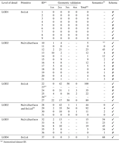
We have listed the results of the three analyses in Table 1. The results show a substantial variation in the quality of the analysed datasets. Some datasets are almost valid, while in some almost all primitives are invalid. Perfectly valid datasets are very rare, as LOD1 models contained at least 0.1% to 0.5% errors. As par-tially visible in Table 1 we have found that no two datasets are alike when it comes to errors (see also Fig. 5). This is likely caused by different software packages used for modelling, dif-ferent workflows used to produce the models, and the difdif-ferent companies with different internal procedures for quality assur-ance. This prevents us to generalise a common conclusion about the quality, and makes it difficult to come up with a list of com-mon errors. While one dataset isinfestedwith one type of error, such error is not found at all in another one.
It should be noticed that models in LOD1 are almost all valid, except a few isolated exceptions; the errors are mostly duplicated vertices. Also, some datasets have an invalid syntax (schema), which meant that we could not parse it to validate it. Observe that for many invalid ones we could still parse the files and validate their geometric primitives and their semantics; the errors were located in parts that were not relevant to our task.
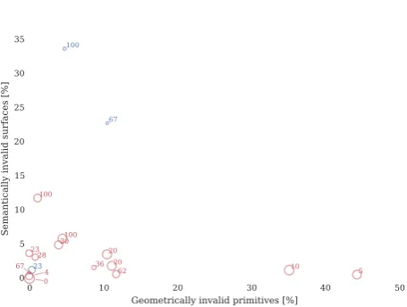
Another general observation is that the geometric and semantic errors are not correlated (see Fig. 6). While some datasets are full of geometric errors, they fare much better in the semantic aspect. Furthermore, the size of the dataset appear not to have an influence on the errors—we had expected that smaller datasets might have been prepared more carefully. But it turns out that is not the case.
1
https://github.com/tudelft3d/val3dity and http: //geovalidation.bk.tudelft.nl
1xx 2xx 3xx 4xx Total
Decomposed geometric errors by dimension
0 Geometric errors by dimension
Figure 5: Decomposition of the geometric errors into 4 levels (example an LOD2 with solids). Each of the datasets has a unique configuration of errors preventing a common conclusion about the quality of CityGML datasets. Example of dataset #27.
0 10 20 30 40 50
Table 1: Results of the validation of the test datasets. The share of errors is expressed in per cents.
Level of detail Primitive ID(a) Geometric validation Semantics(f)
Schema 1xx 2xx 3xx 4xx Total(b)
LOD1 Solid 1 0 0 0 0 0 – ✗
2 0 0 0 0 0 – ✓
3 0 0 0 0 0 – ✓
4 0 0 0 0 0 – ✓
5 0 0 0 0 0 – ✗
6 0 0 0 0 0 – ✗
7 0 0 0 0 0 – ✓
8 0 0 0 0 0 – ✓
9 0 0 0 0 0 – ✗
LOD2 MultiSurface 10 1 4 – – 5 (e) ✓
11 0 0 – – 0 0 ✓
12 2 21 – – 23 45 ✓
13 10 2 – – 12 4 ✗
14 0 1 – – 1 12 ✓
15 0 9 – – 9 2 ✓
16 4 8 – – 12 1 ✗
17 5 0 – – 5 5 ✗
18 0 0 – – 0 4 ✗
19 0 0 – – 0 1 ✗
20 0 4 – – 4 6 ✗
21 0 1 – – 1 3 ✗
LOD2 Solid 22 0 42 58 0 100 – ✓
23(c) – – – – – – ✗
24 0 31 1 3 35 – ✗
25 4 0 16 2 22 – ✓
26(c) – – – – – – ✗
27 22 17 50 0 89 – ✓
LOD2 MultiSurface
andSolid(d)
28 0 42 1 1 44 0 ✓
29 2 35 54 0 92 4 ✓
30 0 10 0 1 11 2 ✓
31 0 0 0 0 0 0 ✓
LOD3 MultiSurface 32 2 13 – – 15 54 ✓
33 6 5 – – 11 23 ✓
34 8 10 – – 19 45 ✓
35 5 0 – – 5 34 ✓
36 0 0 – – 0 1 ✗
LOD4 Solid 37 0 0 3 0 3 68 ✓
(a)Anonymised dataset ID.
(b)The decomposed errors may not sum up to the totals due to rounding. Most of LOD1 datasets are not 100% valid, they
are rather between 99.5% and 99.9% valid.
(c)The dataset could not be read by our software due to errors while parsing the GML input.
(d)These datasets contain both theSolidandMultiSurface(usually realised through theXLinkmechanism). (e)Dataset withMultiSurfacesbut without semantic information.
(f)Our approach for the semantic validation falls short with some datasets (further explained in Fig. 15), and high values
should be ignored.
4.5 Common errors
We have examined the errors in the datasets and the first obser-vation is that errors appear to berandomin some datasets, while in some datasets they are of asystematicnature. For instance, Fig. 7 shows a dataset with one random error: a missing wall from a building. On the other hand, we have encountered repeti-tive errors that could have been caused by software or by the lack of guidelines. For instance, wrong orientation of linear rings. We came up with a list of errors that can be found in multiple datasets and describe them in the continuation, in no particular order.
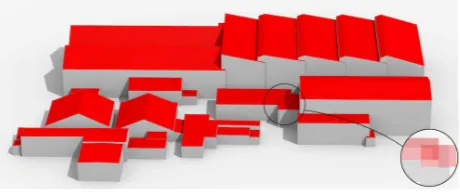
4.5.1 Geometries not properly snapped A common cause for invalid solids (Error 3xx) are geometries that are not snapped together, which causes surfaces to intersect and/or to result a non-watertight solid. One example is shown Figure 8. Observe that the invalid solids which we have encountered often look correct with a visual inspection, and only by zooming in one can detect these. As explained in Section 2.4, we used a snapping tolerance of 1mm on the input coordinates. Thus for such errors the vertices are further than this apart.
Figure 7: An example of a seemingly random error: missing wall polygons from a building, causing invalid solids. This error is likely caused by the conversion of the dataset from another for-mat, during which the generation of the polygons failed.
Figure 8: Not snapped geometries are the usual cause of invalid solids.
while modelling. Despite this, we have detected a fair share of semantically incorrect surfaces. However, we have not encoun-tered a pattern. Hence we cannot focus on a particular type of such errors. Fig. 9 shows an interesting example of a semanti-cally invalid surface.
Most of the datasets are semantically valid, and we suspect that this is because in many cases the semantic information was added as a post-processing by using the exact same method we use for validation (by using the normal of the surfaces).
Figure 9: This example illustrates two inconsistencies: (a) a
RoofSurfaceused to store a vertical interior wall (right end of the building); and (b) a building complex decomposed into multi-ple buildings and separated by duplicatedWallSurfaces. While the former error is normally noticeable by a visual inspection while modelling, it likely went unnoticed because it is obstructed, beinginsidethe building.
4.5.3 Non-planarity As explained in Section 2.4, we have used two methods to detect non-planar polygons, each having their own error code (203 and 204). The results show that there are many non-planar polygons (e.g. dataset #28 has more than 40% invalid polygons due to planarity issues), and we would highlight this as the most common error in all the datasets we
<0.05 <0.1 <0.25 >=0.25 All
Errors decomposed by threshold [m]
0 1000 2000 3000 4000 5000
Number of errors of type 203
85.5 % 4.3 %
5.4 % 4.8 % Error 203 (NON_PLANAR_POLYGON_DISTANCE_PLANE)
Figure 10: Decomposition of the planarity errors (Error 203) into the distance from the fitted plane. Most of the errors are due to deviations of a few centimetres. Example from dataset #24.
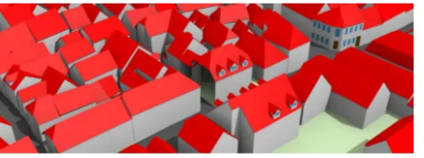
Figure 11: A common error we have noticed is the wrong orien-tation of semantic surfaces stored inMultiSurface. In this ex-ample, the correctly orientedRoofSurfacesare shown in green, and those with the inverted orientation (errors) are shown in red.
tested. Non-planar polygons may cause issues when calculating their area, and in visualisation (texturing), and can—if the devi-ation is very large—cause intersections with other surfaces in a solid. We have decomposed the errors related to planarity by their severity (in case of the Error 203: by the deviation from the fitted plane). The decomposed errors show that most planarity errors are caused by deviations of just a few centimetres (Fig. 10), which is perhaps not an issue for many applications, but is nonetheless invalid according to the internal standard.
This is probably the reason why they have not been noticed, as it is visually impossible to detect them. Furthermore, the large deviations visible in the plot are mostly found in very large poly-gons (roof of a 50m long warehouse), where this inconsistency is hard to notice, even if gross.
5. DISCUSSION, RECOMMENDATIONS & FUTURE WORK
5.1 General observations
In our analysis we have encountered many different errors, of which some are common across multiple datasets. We suspect that data producers perform visual quality checks by removing er-rors that can be caught with a manual inspection. This leaves the following reasons why some datasets have a considerable num-ber of errors: (1) practitioners are simply not aware of possible errors and of the international standards; (2) the modelling soft-ware has no validation support; and (3) the produced data works in the applications intended for the data (which often appears to be visualisation), hence the errors which may influence other ap-plications are simply undetected or ignored.
The analysis of the datasets shows some patterns interesting to note. First, it appears that datasets of a finer LOD are more prone to errors in comparison to their coarser counterparts; this is due to the complexity of the geometry. Datasets in LOD1 and syn-thetically generated datasets contain least errors, and performed best in our experiments. Second, specific modelling conventions resulted in gross errors of otherwise fine datasets. For instance, the dataset #29 contains 92% of invalid solids. The reason be-hind this error is the modelling approach of assigning a joint
GroundSurfaceto multiple building parts that are connected.
Otherwise, most solids would be valid. 5.2 Remedies
These common errors could be solved by imposing constraints and/or using an ISO-compliant validator. Furthermore, advanc-ing the topological functionalities of the software to prevent them would also greatly help (e.g. enable snapping). However, we are also under the impression that some of these errors are directly caused by software: some datasets have been produced in formats other than CityGML (e.g. IFC, DXF, DAE), and the conversion to CityGML introduced new errors.
In addition to modelling software, the errors may also depend on the data source that is used as input. Different data sources (e.g. building footprints, point clouds) dictate the information that can be observed by the modeller. For instance, when using the or-thophoto, sometimes due to certain hidden surfaces (e.g. outer ceiling surface), overlaps are intentionally created between build-ing surfaces to ensure that there are no gaps them. Such intention then becomes a topological error.
Despite advancements in the repair of dataset (Zhao et al., 2013; Alam et al., 2013), we deem that in the foreseeable future it is not realistic to expect a universal solution that would automatically repair data—it would rather be beneficial to focus on preventing errors while modelling. While such automatic solutions do man-age to repair a fair share of 3D models, it is simply hard to account all cases which we have encountered, and we believe that manual repair will still dominate as the preferred method for healing 3D models.
5.3 Impact on applications
While our results show that many datasets contain a substantial amount of errors, their severity eventually depends on their in-tended use. Some of the errors have no influence on the applica-tion, while others may completely prevent their use. Therefore it is not only a matter of analysing the quantity of errors in 3DCMs but also of identifying those which has severe impact on the ap-plications. For instance, using the data for visualisation purposes
is likely less prone to errors than when using it for applications such as the simulation of the airflow in a city with computational fluid dynamics. In fact, the inability to use 3D city models for a specific purpose has been the main driving factor of some re-lated work, e.g. Steuer et al. (2015), Mulder (2015), and Sindram et al. (2016) develop repair techniques specifically designed to overcome topological errors that prevent the computation of the volume of buildings.
Besides the geometric aspect, many applications are prone to se-mantic errors as well. For instance, the estimation of the solar potential of roof surfaces is susceptible to erroneous semantics of surfaces (e.g. a wall being mislabelled as a roof surface and accounted in the total area feasible for the installation of solar panels). While there is a great deal of investigating the propa-gation of error in GIS (e.g. see the overview in Biljecki et al. (2015a)), the propagation of errors described in this paper has not been investigated, and it is a topic for future work. This is especially important in the context of open data, since it is to be expected that they will be used in a wide range of purposes. As documented by several papers, e.g. see (Salimzadeh et al., 2016; Nouvel et al., 2015; Boeters et al., 2015; Kehl, 2015), researchers show variable level of satisfaction about publicly available 3D data, depending on the used application.
It is important to note that besides the employment of models in spatial analyses, errors may influence other tasks such as storage in databases, maintenance of data, and conversion to other for-mats. For instance, non-planar polygons may present a problem in the triangulation, when converting CityGML models to com-puter graphics formats such as OBJ.
5.4 Limitations, open questions, and future work
The software we used does not cover all aspects of quality, hence not all errors have been detected. While manually inspecting the datasets we have realised that there are other types of inconsis-tencies which we recommend to investigate in future work. In the continuation, we list the most important ones.
One relevant CityGML conformance requirement—that we not consider in this paper—is the one concerned withBuildingand
BuildingPart. The standard states that if a building is one ho-mogeneous part it should be represented as oneBuilding, but differentBuildingPartshould be used if the roof types or if the number of storeys differ, or if the addresses are different. We found several questionable cases in our datasets, see for in-stance Figure 12 where a large building complex is modelled as
oneBuildinghaving severalBuildingPart, while it should
ar-guably be modelled with different buildings (at least from the Eu-ropean perspective). This example (along with the one in Fig. 13) also shows that the notion of a building varies between datasets. Our prototype can detect such cases by finding buildings with an
unusually large number of polygons and of a large surface area, but this solution is not mature enough to carry out rigorous ex-periments (e.g. this approach flags large valid buildings such as cathedrals). Belussi et al. (2015) propose a solution based on OCL constraints, but their implementation does not support inte-rior boundaries in polygons at this moment.
The previous figure doubles as another example of an idea for future work: overlap of features, which has not been covered at this moment. We have noticed that at several locations the
BuildingPartsare overlapping, which cause the building
vol-ume, if calculated by summing the volumes of the parts, to be larger than the true value.
This error is also illustrated in Fig. 13, where awnings (stored as
MultiSurfaces) overlap with the facade (stored as aSolid),
i.e. they are not clipped. As previously mentioned, we do not analyse the topological relationships between different objects, as this is a topic for future work. Such errors would have been pre-vented by more advanced modelling capabilities and constraints in the software.
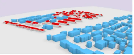
Figure 13: Outer surfaces protruding inside the walls. The validation of the level of detail (LOD) in datasets presents an important idea for future work, for instance checking if the features have been acquired according to the LOD stated in the metadata. Fig. 14 shows an example of a dataset of a heteroge-neous LOD. This is a simple case which can be detected because the buildings are stored in different CityGML LODs, but there are other examples in which a building is stored as an LOD3 but it is evident that it is an LOD2 because it contains no openings (for a related example compare the buildings in Fig. 7). This can involve developing methods to automatically detect the LOD of objects, based on related work in 2D (Touya and Brando-Escobar, 2013), but it is hampered by the fact that there is a great variation between buildings when it comes to complexity, hence inferring their LOD may be complex. For example, a garage in LOD3 may be modelled as a simple block akin to an LOD1, and still be valid (Biljecki et al., 2016).
Figure 14: Inconsistent level of detail of the dataset. The limitations of our method yields a number of false posi-tives and false negaposi-tives, especially in the semantic validation
(see Figs. 15 and 16 for examples). For instance, a shortcom-ing in the semantic validation is that we cannot distshortcom-inguish be-tweenOuterFloorSurfaceandRoofSurface, since they are validated against the same range of angles (see Figure 4).
Figure 15: Examples of the shortcomings of our semantic vali-dation. The left image shows a false negative—aWallSurface
is modelled as a volume, and thetopshave the normals point-ing upwards resultpoint-ing in an error. The render on the right shows a building with interior floors modelled asGroundSurface(in orange). This is a false negative because the error has not been detected by our normal-based approach. Oddly enough, the one
GroundSurfacewhich is supposed to be there is missing, but
this omission has not been detected either. Both situations are likely caused by the IFC origin of the dataset, as in the conver-sion the geometry was not adapted to the structure expected by CityGML. Making the semantic validation more intelligent is a priority for future work.
Figure 16: Example of an uncertain situation: a wall modelled as aRoofSurface, which is not correct but it went unnoticed by our validation software (false negative) due to the angle of the normal. If the wall was modelled as aWallSurfaceit would be flagged as a semantically invalid surface, i.e. a false positive. It is likely that this dataset was converted to CityGML from another format, and during the conversion the surfaces have been seman-tically enriched according to orientation of the normalsoutwitting our validation procedure. Imagery (c) 2016 Microsoft Corp and Pictometry International Corp.
For this paper, we consider 5 classes of 9 ofBoundarySurface
types in LOD2, with respect to the conformance requirements in CityGML. The classes in LOD3 will includeWindowandDoor, which cannot be validated only by normal, and have not been solved in our software. Validating the semantics is becoming an increasingly important task due to a growing number of semanti-cally enriched datasets (Rook et al., 2016).
6. CONCLUSION
In this paper we have analysed numerous CityGML datasets from different sources to assess their quality and derive a list of preva-lent errors. Our analysis shows that there is a large variation in the quality of CityGML datasets, and that each dataset is unique when it comes to errors. This is likely caused by different soft-ware packages which were used and different acquisition com-panies using different modelling guidelines resulting in different types of errors. None of the datasets we have tested was perfect, but some LOD1 datasets come very close to 100%.
The non-planarity of polygons is by far the most common error we have encountered (error 203 in Figure 3). Other errors are less present, and we cannot say that there are omnipresent errors because the datasets are heterogeneous: while some datasets are full of a particular error, others are free of them. It should be noticed that this does not mean that errors of type 3xx (e.g. a shell having cracks and/or overlapping surfaces) do not appear, but since with our methodology all the primitives at one level must be valid to continue to the next one, then very often the validation of the properties of a solid is not attempted. Errors related to rings and polygons are thus more likely to be reported, but these are simpler to avoid and thus we were surprised that so many datasets have simple errors such as duplicate points or non-planarity.
In our opinion, most of the detected errors are easily preventable during the production of data. For 3D models that are automat-ically reconstructed, slight modifications to the algorithms used, e.g. triangulating non-planar faces or simply removing duplicate points, could have a big impact on the quality. For 3D models that are manually produced, it seems that the operators are of-ten not aware of the quality rules used in the GIS world, and they produce their models by using Boolean operations such that their modelslooknice—if they were made aware of the rules then many of them could be easily avoided. However, this comes as no surprise because the quality of 3D city models is still an in-sufficiently explored topic, and the influence of particular errors onto specific spatial analyses has not been investigated.
Finally, it is important to note that we have carried out the valida-tion entirely using our own software, which is released as open-source (under a GPL licence), so we hope that practitioners will use it to verify their datasets before releasing them for use.
ACKNOWLEDGEMENTS
We acknowledge the availability of the datasets from the follow-ing sources: Karlsruhe Institute of Technology, City of Berlin, District Administration Recklinghausen, Ordnance Survey Great Britain, City of the Hague, maila-push GmbH Darmstadt, GEO-RES, GTA Geoinformatik GmbH, City of Hamburg, University of Bonn, Landesvermessungsamt NRW, City of Linz, City of Lyon, City of Montreal, Technical University of Munich, Delft University of Technology, New York City Department of Infor-mation Technology and Telecommunications, City of Rotterdam, Singapore Land Authority, UVM Systems GmbH, CENSAM / Singapore-MIT Alliance for Research and Technology, Swiss Fed-eral Office of Topography, Geneva’s Territory Information Sys-tem (SITG), and the City of Z¨urich.
This research is supported by (i) the Dutch Technology Founda-tion STW, which is part of the Netherlands OrganisaFounda-tion for Sci-entific Research (NWO), and which is partly funded by the Min-istry of Economic Affairs; (ii) China Scholarship Council (CSC); and (iii) Singapore Land Authority.
References
Agugiaro, G., 2016. First steps towards an integrated CityGML-based 3D model of Vienna. ISPRS Ann. Photogramm. Remote Sens. Spatial Inf. Sci. III-4, pp. 139–146.
Alam, N., Wagner, D., Wewetzer, M., Pries, M. and Coors, V., 2013. Towards automatic validation and healing of CityGML models for ge-ometric and semantic consistency. ISPRS Ann. Photogramm. Remote Sens. Spatial Inf. Sci. II-2/W1, pp. 1–6.
Alam, N., Wagner, D., Wewetzer, M., von Falkenhausen, J., Coors, V. and Pries, M., 2014. Towards Automatic Validation and Healing of CityGML Models for Geometric and Semantic Consistency. In: Inno-vations in 3D Geo-Information Sciences, Springer International Pub-lishing, pp. 77–91.
Belussi, A., Migliorini, S., Negri, M. and Pelagatti, G., 2015. Valida-tion of spatial integrity constraints in city models. In: Proceedings 4th ACM SIGSPATIAL International Workshop on Mobile Geographic In-formation Systems, ACM, pp. 70–79.
Biljecki, F., Heuvelink, G. B. M., Ledoux, H. and Stoter, J., 2015a. Propa-gation of positional error in 3D GIS: estimation of the solar irradiation of building roofs. International Journal of Geographical Information Science 29(12), pp. 2269–2294.
Biljecki, F., Ledoux, H. and Stoter, J., 2015b. Improving the consistency of multi-LOD CityGML datasets by removing redundancy. In: 3D Geoinformation Science, Springer International Publishing, pp. 1–17.
Biljecki, F., Ledoux, H. and Stoter, J., 2016. An improved LOD speci-fication for 3D building models. Computers, Environment and Urban Systems 59, pp. 25–37.
Biljecki, F., Stoter, J., Ledoux, H., Zlatanova, S. and C¸ ¨oltekin, A., 2015c. Applications of 3D city models: State of the art review. ISPRS Inter-national Journal of Geo-Information 4(4), pp. 2842–2889.
Boeters, R., Arroyo Ohori, K., Biljecki, F. and Zlatanova, S., 2015. Au-tomatically enhancing CityGML LOD2 models with a corresponding indoor geometry. International Journal of Geographical Information Science 29(12), pp. 2248–2268.
Bruse, M., Nouvel, R., Wate, P., Kraut, V. and Coors, V., 2015. An Energy-Related CityGML ADE and Its Application for Heating De-mand Calculation. International Journal of 3-D Information Modeling 4(3), pp. 59–77.
Diakit´e, A. A., Damiand, G. and Gesqui`ere, G., 2014. Automatic seman-tic labelling of 3D buildings based on geometric and topological in-formation. In: Proc. 9th International 3DGeoInfo Conference, Dubai, United Arab Emirates, pp. 49–63.
Hsieh, C.-M., Aramaki, T. and Hanaki, K., 2011. Managing heat rejected from air conditioning systems to save energy and improve the micro-climates of residential buildings. Computers, Environment and Urban Systems 35(5), pp. 358–367.
ISO, 2003. ISO 19107:2003: Geographic information—Spatial schema. International Organization for Standardization.
Janssen, W. D., Blocken, B. and van Hooff, T., 2013. Pedestrian wind comfort around buildings: Comparison of wind comfort criteria based on whole-flow field data for a complex case study. Building and Envi-ronment 59, pp. 547–562.
Kehl, C., 2015. Disseminating large-scale semantic 3D landscape models using open visualisation platforms. European Journal of Geography 6(2), pp. 51–68.
Ledoux, H., 2013. On the validation of solids represented with the inter-national standards for geographic information. Computer-Aided Civil and Infrastructure Engineering 28(9), pp. 693–706.
McKenney, D., 1998. Model quality: The key to CAD/CAM/CAE inter-operability. Technical report, International TechneGroup Incorporated, Milford, OH.
Mulder, D., 2015. Automatic repair of geometrically invalid 3D city building models using a voxel-based repair method. Master’s the-sis, 3D geoinformation group, Delft University of Technology, Nether-lands.
Nouvel, R., Mastrucci, A., Leopold, U., Baume, O., Coors, V. and Eicker, U., 2015. Combining GIS-based statistical and engineering urban heat consumption models: Towards a new framework for multi-scale policy support. Energy and Buildings 107, pp. 204–212.
OGC, 2007. Geography markup language (GML) encoding standard. Open Geospatial Consortium inc. Document 07-036, version 3.2.1.
OGC, 2012. OGC city geography markup language (CityGML) encoding standard. Open Geospatial Consortium. Document 12-019, version 2.0.0.
OGC, 2016. OGC CityGML quality interoperability experiment. Open Geospatial Consortium. Document OGC 16-064.
P´edrinis, F., Morel, M. and Gesqui`ere, G., 2015. Change Detection of Cities. In: 3D Geoinformation Science, Springer International Pub-lishing, pp. 123–139.
Rook, M., Biljecki, F. and Diakit´e, A. A., 2016. Towards automatic se-mantic labelling of 3D city models. ISPRS Ann. Photogramm. Remote Sens. Spatial Inf. Sci.
Salimzadeh, N., Sharif, S. A. and Hammad, A., 2016. Visualizing and Analyzing Urban Energy Consumption: A Critical Review and Case Study. In: Construction Research Congress 2016, American Society of Civil Engineers, Reston, VA, pp. 1323–1331.
Sindram, M., Machl, T., Steuer, H., P¨ultz, M. and Kolbe, T. H., 2016. Voluminator 2.0 – speeding up the approximation of the volume of de-fective 3D building models. ISPRS Ann. Photogramm. Remote Sens. Spatial Inf. Sci. III-2, pp. 29–36.
Stadler, A. and Kolbe, T. H., 2007. Spatio-semantic coherence in the integration of 3D city models. Int. Arch. Photogramm. Remote Sens. Spatial Inf. Sci. XXXVI-2/C43, pp. 1–8.
Steuer, H., Machl, T., Sindram, M., Liebel, L. and Kolbe, T. H., 2015. Voluminator—approximating the volume of 3D buildings to overcome topological errors. Springer, pp. 343–362.
Stoter, J., de Kluijver, H. and Kurakula, V., 2008. 3D noise mapping in ur-ban areas. International Journal of Geographical Information Science 22(8), pp. 907–924.
Touya, G. and Brando-Escobar, C., 2013. Detecting Level-of-Detail In-consistencies in Volunteered Geographic Information Data Sets. Car-tographica: The International Journal for Geographic Information and Geovisualization 48(2), pp. 134–143.
van Walstijn, L., 2015. Requirements for an integral testing framework of CityGML instance documents. Master’s thesis, Institute of Geodesy and Geoinformation Science, Technische Universitaet Berlin.
Zhao, J., Ledoux, H. and Stoter, J., 2013. Automatic repair of CityGML LoD2 buildings using shrink-wrapping. ISPRS Ann. Photogramm. Re-mote Sens. Spatial Inf. Sci. II-2/W1, pp. 309–317.