SEAMLESS INDOOR-OUTDOOR NAVIGATION
FOR UNMANNED MULTI-SENSOR AERIAL PLATFORMS
Daniel Serranoa, Maarten Uijt de Haagb, Evan Dillb, Santi Vilardagaa, Pengfei “Phil” Duanb
aAerospace Technology Center (CTAE) of Fundació Privada ASCAMM, Barcelona, Spain b
Ohio University, Athens, Ohio, USA
KEY WORDS: Sensor integration, Global Positioning System, inertial navigation, electro-optical sensors, laser range scanners, iterative closest point, simultaneous localisation and mapping.
ABSTRACT:
This paper discusses the development of navigation algorithms to enable seamless operation of a small-size multi-copter in an indoor-outdoor environment. In urban and indoor environments a GPS position capability may be unavailable not only due to shadowing, significant signal attenuation or multipath, but also due to intentional denial or deception. The proposed navigation algorithm uses data from a GPS receiver, multiple 2D laser scanners, and an Inertial Measurement Unit (IMU). This paper addresses the proposed multi-mode fusion algorithm and provides initial result using flight test data. This paper furthermore describes the 3DR hexacopter platform that has been used to collect data in an operational environment, starting in an open environment, transitioning to an indoor environment, traversing a building, and, finally, transitioning back to the outdoor environment. Implementation issues will be discussed.
1. INTRODUCTION
This paper discusses the development of navigation algorithms to enable seamless operation of a small-size multi-copter in an indoor-outdoor environment. In urban and indoor environments a Global Positioning System (GPS) position capability may be unavailable not only due to shadowing, significant signal attenuation or multipath, but also due to intentional denial or deception. The proposed navigation algorithm uses data from a GPS/GLONASS receiver (pseudorange and carrier-phase measurements), multiple 2D laser scanners (point-cloud data), and an Inertial Measurement Unit (IMU) (delta-v’s and delta -theta’s). Although 2D vision cameras were also available on the Unmanned Aerial Vehicle (UAV) platform, algorithms using this data are not discussed in this paper.
To enable operation of UAVs at any time in any environment, a precision navigation, attitude, and time capability is required that is robust and not solely dependent on GPS. To improve availability and guarantee continuity of service in GPS-challenged environments, GPS can be integrated with an IMU also add integrity, continuity and availability to the solution.
Alternative navigation technologies may include (a) the integration of inertial sensors with imagery and laser scanners [1], (b) beacon-based navigation (i.e. pseudolites, UWB) [3], (c) or navigation using signals of opportunity [3]. The integration strategy addressed in this paper is an example of category (a) and uses a combination of GPS, IMU and multiple laser scanners. In aerial robotics, it is required to estimate the platform’s pose (position and attitude) in three dimensions (3D) and therefore solve for 6 degrees-of-freedom (6DOF): extract features such as line segments and points from the laser scans and use these features to estimate the position and heading of the robot or aid an inertial navigator. Alternatively, a large amount research papers have addressed laser scanner-based 3DOF Simultaneous Localisation And Mapping (SLAM) methods such as the grid-based SLAM method described in [7] or methods that use some form of scan-matching such as the Iterative Closest Point (ICP) approach [8]. Rather than using a 2D laser scanner, one could choose to use sensor that produces a 3D point cloud such as a 3D laser scanner or even a 3D imaging sensors. Examples of the latter are the Swissranger, PMD or the Kinect. In that case, features could be extracted from the resulting 3D point cloud and used for 3D pose estimation. For example, in [9] and [10] planar features are extracted from the point cloud and used to obtain 6DOF estimates either with or without IMU. Alternatively, the translational and rotational motion (6DOF) of the platform can be estimated by performing ICP on consecutive point clouds [4].
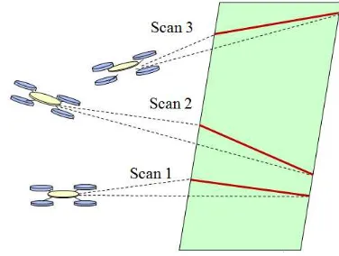
Figure 1. Observation of planar surfaces using multiple laser scans taken at consecutive platform positions.
2D laser scanners can be used for 3D pose estimation, as is done in the algorithm presented in this paper. The 2D sensor could be turned into a 3D sensor by using an additional motor to rotate the laser scanner or an additional rotating mirror [4]. The method described in [11] uses the aerial platform itself to rotate the 2D laser scanner (see Figure 1). The method furthermore assumes a structured environment and uses planar feature to estimate the 3D pose of the platform. Recently, SLAM methods have been develop that use a 2D laser scanner on a small-size indoor aerial platform. In [12] the authors present an approach that combines a 2D SLAM method with a 3D navigator based on an IMU. They use a 2D occupancy grid map and use a bilinear interpolator to achieve better scan matching performance. This method has been implemented in ROS as part of the Hector SLAM package. [13] describes another implementation using a modified 2D laser scanner. Like the previous paper, a 2D map is being generated, however, this time support is included for multiple floors and loop closure. ICP is used to perform scan matching with a grid-based map. A mirror is added to deflect a section of the 2D laser field-of-view (FoV) to obtain an altitude measurement . The remaining 2 degrees of freedom are obtained from the IMU. The authors in [14] utilize the same modified 2D laser scanner as used in [13] and similarly, compute the pitch and roll directly from the IMU, reducing the problem to a 4DOF incremental motion estimation problem. In contrast to [12] and [13], the authors introduce the concept of multilevel-SLAM which uses multiple 2D maps associated with potential level changes (i.e. tables) defined at discrete altitudes. The deflected laser altitude measurement is used in combination with the vertical velocity estimate are used to identify the level of each point of the point cloud.
The method proposed in this paper builds on concepts discussed in [11][12][13] and [14], but extend the operational scenario to include the outside environment where GPS is available
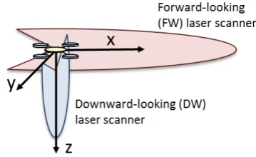
allowing the inclusion of GPS measurements [16]. Furthermore, the 2D laser scanner has not been modified by adding a deflection mirror for altitude measurements. Instead a second low-range 2D laser scanner has been included pointing downward and scanning in the platforms cross-track direction (yz-plane). This installation orientation is illustrated in Figure 2 and aims to increase the instantaneous field of view. The addition of a third laser scanner has also been investigated, but that configuration is not the focus of this paper.
Figure 2. Installation orientations of the two 2D laser scanners.
2. IMPLEMENTATION DETAILS
To evaluate the algorithms proposed in this study, data was collected using a commercially available hexacopter shown flying through a hallway of the Stocker Center (the Ohio University engineering building) basement in Figure 3. The basic frame of this platform was purchased as a kit and then modified to accommodate the payload required for this research. The designed hexacopter has demonstrated the capability of flying both indoors and outdoors while collecting laser, GPS, inertial, barometric, and digital imagery data.
Figure 3. 3DR hexacopter with sensor payload while flying in the Stocker center basement.
The most crucial modifications made to the base hexacopter platform are the mounts of each sensor. The location of these sensors with respect to the platform can be seen in Figure 4. The GPS receiver is a NovAtel OEMSTAR 12-channel L1 receiver capable of making both code-phase and carrier-phase measurements. The IMU is an Xsens MTI sensor which makes 3D acceleration, angular rate and magnetic heading measurements at an update rate of 100Hz. The camera consists of a PointGrey FireFly MV color camera running at 30
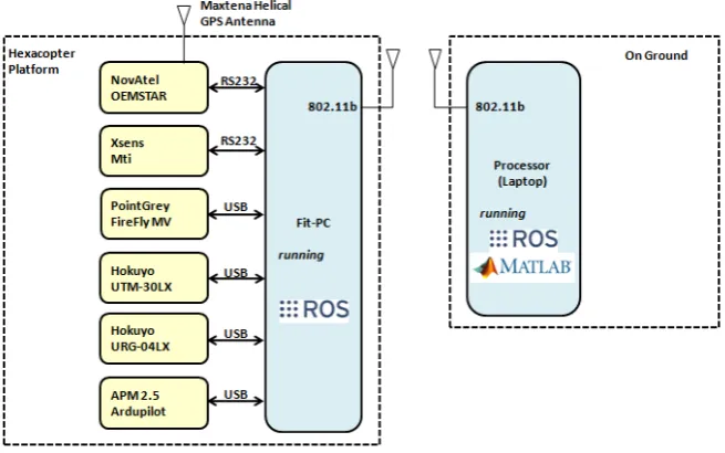
frames-per-second (fps). Finally, two laser scanners are mounted on the platform in the configuration shown in Figure 2. The forward-pointing laser scanner is a long-range (30m) Hokuyo UTM-30LX and the downward pointing laser scanner is a short-range (4m) Hokuyo URG-04LX. The base edition of the hexacopter is already equipped with a basic autopilot, the APM 2.5, which includes a baro-altimeter. Figure 5 depicts the interconnections of the entire data collection system. Using either a RS232 or a USB for communication, each of the sensors is connected to a
FitPC embedded processor, which is mounted just under the main sensor stack on the hexacopter. This FitPC contains an Intel Atom Z530 and runs the Robotic Operating System (ROS) on an Ubuntu operating system. For diagnostic purposes and communication with each of the sensors during flight, an 802.11b wireless connection is established between the FitPC
and a ground station. During data collections, all of the desired sensor data is recorded on the FitPC, stored in "rosbags", and then offloaded to the ground station where ROS and Matlab are used to analyze the data.
Figure 4. Sensor locations on board the 3DR hexacopter.
To allow for operation of this platform with the selected array of sensors, a weight and power consumption analysis was performed. The weight results are shown in Table 1. Given a weight of over 4kg for the combined platform and payload, the motors were upgraded to produce a maximum of 1.38kg of thrust per motor. These motors yield a possible 7.38kg of thrust if all 6 motors are operating at their upper limit. This excess amount of thrust allows the pilot to have reserved power for the purpose of correcting for external sources of environmental interference such as wind gusts during flight. For normal flight operations, the motors draw a combined current between 50 and
60 amps. Separate batteries for the motors and sensor payload were selected; the battery connected to the motors was chosen to be a 4 cell, 5300mah Lithium Polymer unit allowing for at least 5 minutes of flight time without worrying about discharging it below safe levels. To power all the electronics, a much smaller Lithium Polymer battery was chosen which contained 3 cells and 2200mah. This battery can run all the electronics for over an hour and is directly connected to a power converter to output the 5 and 12 volt sources necessary to power the varying electronics.
Figure 5. Hardware interface block diagram.
To accurately fuse the sensor information gathered on this platform, relative lever arms have been measured. All lever arms were measured relative to the center of the IMU. Using the specified origin, a coordinate frame was designated by the
x-axis out of the nose of the platform, the y-x-axis out of the left side, and the z axis pointing upward as illustrated in Figure 2.
3. METHODOLOGY
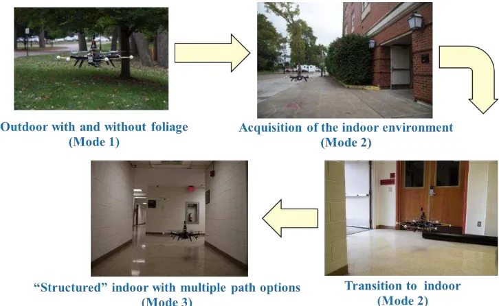
The operational scenario that is being considered is summarized in Figure 6. While operating in the outdoor environment with enough GPS availability the algorithm relies mainly on the tight integration of GPS and IMU with the aid of an altimeter (barometric and/or laser); this operational phase is referred to as Mode 1. Next, the UAV acquires the building it is going to enter and prepares for the transition to the indoor environment (Mode 2).
During this transition the number of available satellite significantly reduces, requiring augmentation of the filter with additional information from the laser scanners. Finally, when inside the building GPS measurements are completely omitted from the solution, and the filters only rely on the laser-scanner, altimeter and IMU data (Mode 3). In addition to the complementary 3D pose estimator, a SLAM algorithm will be included specifically for the map and error estimation.
Figure 6. Operational scenario modes of the aerial platform.
While operating in the outdoor environment, a tightly coupled GPS/INS algorithm will be used based on the algorithm proposed in [1]. In addition, this integration structure will include a baro-altimeter input. This addition will allow for calibration of the altimeter in the presence of GPS. The GPS/INS estimator uses a separate estimator for 3D position and dynamics, the latter solely driven by carrier-phase measurements. The basic architecture of the algorithm is shown in Figure 7. The dynamics estimator is a complementary Kalman filter (CKF) with error state vector:
[ ] (1)
where is the velocity error in the NED frame,
is the miss-orientation vector,
is the gyro bias vector,
is the specific force bias error.
with corresponding continuous-time state transition matrix:
[
[ ]
]
(2)
A clock drift term could also be added to the error state vector. After the CKF update step, the dynamic filter error states are fed back to the attitude and navigation computation blocks. The measurement vector is given by:
(3)
where is the sequential carrier-phase difference for satellite ‘j’ (equal to ), is the change in user position as computed by the inertial, consists of the transpose of the line-of-sight vector to satellite ‘j’, , and are two compensation terms for geometry and Doppler change correspondingly [17], and is the sequential clock drift error. GPS sequential difference geometry including change in position, is shown in Figure 8. Note that equation (3) can be extended to a “difference-of-difference” measurement by taking the difference of the sequential difference of satellite ‘j’ and the sequential difference of a key satellite ‘k’. This new difference term will remove the receiver clock drift error from the state vector.
The measurement matrix, H, which relates the dynamics filter error state in (1) to equation (3) can be derived by expanding and evaluating the sensitivity of the inertial term in (3):
̃ ∫ ̃
[ ̃ ̃ ] (4)
where d is the lever arm between the IMU and the GNSS receiver.
Figure 7. Integration strategy when GPS is available.
Figure 8. GPS Sequential difference geometry.
In equation (4) the tilde ‘~’ indicates parameters affected by the inertial errors. Evaluation of (4) results in the following measurement matrix:
[
[ ] [∫
]
[ ] [∫
]
]
[ [ ] [ ]
[ ] [ ]
]
(5)
where , ,
, and is the discrete-time state transition matrix from time epoch to time epoch derived from F.
The position estimator is a KF whose state vector is given by
[ ] and has an extremely simple form that
includes a forcing function from the dynamics estimator.
(6)
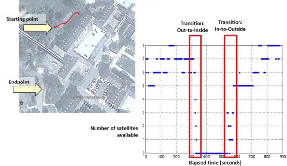
The left image in Figure 9 shows the filtered GPS/INS trajectory superimposed on a photo of Stocker Center and surroundings generated using Google EarthTM. The trajectory starts outside next to Stocker Center (as visualized in Figure 6 top-left) under light foliage.
Figure 9. Filtered GPS solution.
The plot on the right side of Figure 9 shows the visible satellites during the 882 seconds of this UAV flight trajectory. The transitions from the outside to/from the indoor environment can be easily observed. During these transitions the number of satellites rapidly drops when approaching the building (Figure 6 top-right), requiring integration with the INS to maintain a valid position as long as possible.
During the indoor operation of the UAV, no GPS satellites are available and the architecture is solely based on the integration of the IMU with both 2D laser scanners and the baro-altimeter. The functional block diagram of this integration structure is shown in Figure 10. Basically, the method consists of three main estimators: 3DOF SLAM, the altitude estimator and the 6DOF fusion algorithm.
Figure 10. Integration strategy during indoor (mode 3) and transition (mode 2).
In the method shown in Figure 10, the complete 6DOF state vector is separated. The attitude and inertial heading of the platform are computed in the attitude computer and used to compute the body-to-navigation transformation matrix, ̃ . The tilde in ̃ indicates that this matrix is effected by errors in the attitude and heading values, or
̃ . The 3DOF pose estimate ̂ and the 2D map, (defined in only and directions) are estimated simultaneously as follows; transformation matrix ̃
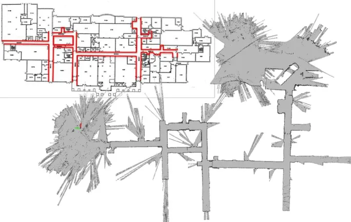
is used to convert the point cloud from the forward-pointing laser scanners to a frame that is aligned with the navigation frame but offset by the platforms translational motion. This point cloud (laser scan) is then matched with an occupancy grid resulting in a 2D pose estimate ̂ and updated 2D map . The method used here is similar to the one described in [7] and [12]. Figure 11 shows the 2D occupancy grid after the UAV has traversed the Stocker basement next to an official map of the Stocker basement.
Figure 11. 2D indoor mapping results.
Figure 12 shows the trajectory consisting of all 2D pose estimates within this established 2D map. Note that the 3DOF SLAM was already activated outside since sparse features were available.
Figure 12. UAV indoor trajectory.
To obtain an estimate of the height, the downward-pointing laser scanner is utilized. Having a downward-pointing laser scanner rather than a mirror that deflects part of the forward-looking laser scanner, not only allows for a better estimate of the relative altitude, but also provides a cross-track vertical scan of the environment resulting in additional information for a 3D map. Furthermore, when assuming a structured environment with flat surfaces, the “slices” of the structured environment can be used to estimate the misorientation, , present in the attitude. The misorientation estimator is outside the scope of this paper.
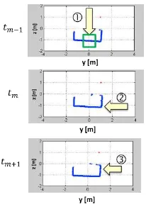
The three images in Figure 13, show the y- and z-coordinates of three consecutive scans of the downward-pointing laser scanner after conversion to a locally-level frame using attitude . Clearly visible in Figure 13 are the basement floor and the walls of the hallway through which the UAV is flying.
Figure 13. Altitude estimation using vertical scans.
The altitude estimator takes a small subset of points around nadir and computes the mean of the z-component to estimate the altitude. Possible outliers could be detected by applying more advanced detection schemes that make sure that the surface that it is looking at is truly a floor surface (i.e. a line in the scan). Alternatively, a simple Kalman filter could be designed to further reduce the noise and detect outliers by screening the filter residuals. Figure 14 shows the results of the laser-based altitude estimator in a plot together with the altitude as provided by the on-board baro-altimeter. Note that the variations in the baro-altimeter are significantly larger than the variations in the laser-based estimator. Naturally, the UAV will show height variations in a tight indoor space due to air fluctuations induced by the aerial vehicle itself.
Figure 14. Altitude estimation results.
Figure 15. Results (left) no integration of GPS with SLAM solution; (right) integration of GPS with SLAM solution.
The 2D trajectory established by the poses output by 3DOF SLAM method and visualized in Figure 12, must be referenced to a true navigation fame (North-East-Down). This can be accomplished when the UAV is operating in the vicinity of buildings with sufficient GPS satellite visibility (during Mode 2). In that case the GPS/INS position and velocity estimator can be used and fused with the “3D position estimate” from the
combined altitude estimator and 3DOF SLAM in a straight forward manner using a simple KF. Figure 15 shows the results of this integration. On the left, the GPS/INS trajectory and the 3DOF SLAM trajectory are shown without integration. Clearly the reference frame is offset and rotated with respect to the NED frame. This can be explained by the limited availability of
-60 -40 -20 0 20 40 60
-70 -60 -50 -40 -30 -20 -10 0 10 20
laser-features at the start point of the UAV trajectory and the unknown initial heading when using the 3DOF SLAM method.
4. SUMMARY AND CONCLUSIONS
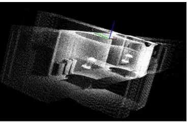
This paper describes an estimation method to determine the 3D pose of a UAV in a mixed indoor-outdoor environment using GPS, inertial and multiple laser scanner measurements. An UAV platform has been designed to collect data in an operational environment. Preliminary results show the successful estimation of the UAV’s 3D position, attitude and 2D indoor map. The next step is to derive the 3D map of the indoor environment using both laser scanners and quantify the algorithms performance using an indoor truth reference map derived using a Riegl LMS-Z360 (see Figure 16).
Figure 16. Laser truth reference map using Riegl LMS-Z360i.
Furthermore, this paper has omitted the use of the on-board vision camera, however, an integration method has already been developed and its evaluation using flight data will be part of a future paper. Finally, the described algorithms are currently being implemented in ROS.
5. ACKNOWLEDGEMENT
Part of this work was performed under the European Union Seventh Framework Programme (FP7/2007-2013), grant agreement number 285417.
6. REFERENCES
[1] Farrell, J. L., GNSS Aided Navigation & Tracking – Inertially Augmented or Autonomous, American Literary Press, 2007.
[2] M. M. Miller, M. Uijt de Haag, A. Soloviev, M. Veth, “Navigating in Difficult Environments: Alternatives to GPS –1,” Proceedings of the NATO RTO Lecture Series on “Low Cost Navigation Sensors and Integration Technology,” SET-116, November 2008.
[3] M. M. Miller, J. Raquet, M. Uijt de Haag, “Navigating in Difficult Environments: Alternatives to GPS – 2,” Proceedings of the NATO RTO Lecture Series on “Low Cost Navigation Sensors and Integration Technology,” SET-116, November 2008.
[4] Nüchter, A., 3D Robotic Mapping – The Simultaneous Localization and Mapping Problem with Six Degrees of Freedom, Springer, 2010.
[5] Pfister, S. T., “Algorithms for Mobile Robot Localization and Mapping Incorporating Detailed Noise Modeling and
Multi-scale Feature Extraction,” Ph.D. Dissertation, California Institute of Technology, 2006.
[6] Soloviev, A., D. Bates, and F. van Graas, “Tight Coupling of Laser Scanner and Inertial Measurements for a Fully Autonomous Relative Navigation Solution,” NAVIGATION, Journal of the Institute of Navigation, Vol. 54, No. 3, Fall 2007, pp. 189-205.
[7] Grisetti, G., C. Stachniss, W. Burgard, “Improving Grid -based SLAM with Rao-Blackwellized Particle Filters by Adaptive Proposals and Selective Resampling,” Proc. Of the IEEE Intl. Conf. on Robot. and Autom., Barcelona, Spain, April 2005, pp. 2432-2437.
[8] Rusinkiewicz, S. and M. Levoy, “Efficient variants of the ICP Algorithm,” Proc. Of Intl. Conf. on 3-D Digital Imaging and Modeling, Quebec City, Quebec, May 2001, pp. 145-152.
[9] Horn, J. P., “Bahnführung eines mobilen Roboters mittels absoluter Lagebestimmung durch Fusion von Entfernungsbild- und Koppelnavigations-daten,” Ph.D. Dissertation, Technical University of Munich, 1997.
[10]Uijt de Haag, M., D. Venable, and M. Smearcheck, “Use of 3D laser radar for navigation of unmanned aerial and ground vehicles in urban and indoor environments,” Proceedings of the SPIE - Volume 6550, SPIE Defense and Security Symposium, Orlando, FL, April 9- 13, 2007.
[11]Soloviev, A. and M. Uijt de Haag, “Three-Dimensional Navigation of Autonomous Vehicles Using Scanning Laser Radars: Concept and Initial Verification,” IEEE Transactions on Aerospace and Electronic Systems, Vol. 46, Issue 1, 2010.
[12]S. Kohlbrecher, O. von Stryk, J. Meyer, U. Klingauf, “A Flexible and Scalable SLAM System with Full 3D Motion Estimates,” Proc. Of IEEE Conference on Safety, Security, and Rescue Robotics, 2011.
[13]S. Shen, N. Michael, V. Kumar, “Autonomous Multi-Floor Indoor Navigation with a Computationally Constrained MAV,” Proc. Of IEEE Conference on Robotics and Automation, 2011.
[14]S. Grzonka, G. Grisetti, W. Burgard, “A Fully Autonomous Indoor Quadrotor,” IEEE Transactions on Robotics, Vol. 28, Issue 1, 2012.
[15]Soloviev, A. and D. Venable, “When GNSS Goes Blind,” InsideGNSS, October 2010.
[16]Dill, E., “Integration of 3D and 2D Imaging Data for Assured Navigation in Unknown Environments,” M.S.E.E. Thesis, March 2011.
[17]Van Graas, F. and A. Soloviev, “Precise Velocity Estimation Using a Stand-Alone GPS Receiver,” NAVIGATION, Journal of the Institute of Navigation, Vol. 51, No. 4.