Application Solar Energy for Charging Battery Mobile Phone
Mohamed Abdulhadi Elmahdi1, Sudjito Suparman2, Sholeh Hadi Pramono2, ¹Electrical Engineering Graduate Student, Faculty of Engineering, Brawijaya University
²Lecturers Master and Doctoral Program Engineering, Brawijaya University Jl. MT. Haryono 167 Malang 65145, Indonesia
E-Mail: [email protected]
Abstract
Photovoltaic energy is the conversion of sunlight into electricity. A photovoltaic cell, commonly called a solar cell or PV, is the technology used to convert solar energy directly into electrical power. A battery charger is a device used to put energy into a secondary cell or recharge able battery by forcing an electric current through it. Digital devices, especially mobile phones, need electricity that can be obtained from local electricity station converted into direct current using proprietary charger. Yet, the users can not always find the local electricity station such as in travelling or in condition where electricity becomes unavailable at the moment. On the other side, the use of local electricity to power mobile phones increases the fossil fuel consumption since the main source of energy for our current local. The solar energy is the ideal solution to the problems of energy and the environment and provides environmental safety factor as the solar energy is clean, renewable energy does not pollute the air and leave no waste. The charge controller is divided into two circuits: overcharge controller and discharge controller. Overcharge controller limits the maximum voltage when recharging process is being held. The circuit implemented is an operational amplifier that works as comparator, of which output controls the transistor that will stop or allow the charging current passed to the battery, the result is able to meet the design characteristics for the controller. These results are very useful for charging battery form sun light and it’s more economical and environmentally friendly and the advantage of the system compared to charger mobile phone ac to dc. And this solution for the electrification of remote areas.
Keywords: controller, solar panel, battery .
INTRODUCTION
On the last couple of decades a lot of effort has been directed towards charging battery mobile phone by solar [1-5]. Solar solution for mobile charging centers in Nigeria has been successfully functioned, though the system has a high initial cost, it has a higher yield on the long run. The energy from this system is environmentally friendly devoid of noise pollution and toxic gas emission. This system may saves mobile charging vendors from known problems such as maintenance of generators, loss of time due to maintenance and system breakdown due to generator failure [1,2].The whole system can be conveniently charge a drained battery of the
mobile phones without the need for main supply or charger and the
application of this circuit using PV cells will help recharging process is available during an emergency [5].
energy specifically, in rural areas and in the desert areas.
In this research I use solar panel as power in the charger battery mobile phone. This research presents the experiment result of a solar energy system. And this system have two modes. Mode one solar energy to charging storage battery ,second mode from storage battery to charger battery mobile phone.
These results are very useful for charging battery form sun light and it’s more economical and environmental and the advantage of the system compared to charger mobile phone ac to dc, and this solution for the electrification of remote areas a battery, charge controller. The commonly used. The charge controller regulates the current added to and drawn from the battery in order to maximize the battery lifetime and for user safety. Because photovoltaic systems produce a direct current.
EXPERIMENT METHOD
In this experiment model presented in solar panel charges a rechargeable battery storage, as shoes in figure. 1. That in turn charges your mobile. This means you can charge your phone even when there is no sunlight at night for example so long as you’ve charged your battery during the day.
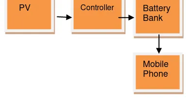
Figure 1. Experiment of solar panel charges a rechargeable battery.
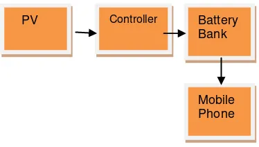
PV is solar panel that converts light into electrical energy, of which output is connected to Controller to manage the charging and discharging over the battery bank when any load (mobile phone or digital devices) is connected.
The Controller is useful to limit the recharging of Battery bank not to be over its maximum voltage and also to disconnect the load when the battery bank has very low voltage. This functions is to prolong the life of the battery bank.
In this experiment , the photovoltaic system is examined for the system charger mobile phone. In which, this system includes two batteries, One of the is photovoltaic with battery and the second one is battery with battery mobile phone. If we need to calculate output of photovoltaic (P.V) volte and current, we should conduct the small charger with a simple experiment to operate with two modules of PV in series. Note that, it should measure variables in six different times of solar radiation for the calculation of input and output of PV. In this study, it should be measured both, the time consumed by P.V to make the storage battery full and what the time consumed, by storage battery to make battery mobile phone is full. This data has been shown in the table 1.
Table 1. Simple data of experiment. PV Battery Storage BATTERY
Charge Controller
Figure . 2. Shows the main task of a charge controller in this experiment is to prevent battery of overcharging and excessive discharge, therefore prolong battery life.
Figure 2. Charge Controller.
The Controller is divide into two main functions. The overcharge controller is useful to limit the recharging of Battery bank not to be over its maximum voltage and also to disconnect the load when the battery bank has very low voltage. This functions is to prolong the life of the battery bank. RESULTS AND DISCUSSION
Solar radiation
Insolation is the solar radiation, when the energy is emitted by the sun in all directions and it reaches the earth’s surface, after being measured the solar radiation in the laboratory of mechanical engineering in six different times start at 9:30 AM in the morning until 2:30 PM in the afternoon. The device that is used for measuring the solar radiation, is called Pyranometer device, and the highest solar radiation around 931.3W/ , which was at 12:30 PM as it is shown in the table 2.
Table 2. Intensity of solar radiation .
According to the result measurement of solar radiation in the figure 2. the radiation is increasing from at 9:30 AM, in the morning until 12:30 PM in the afternoon but at 2:30 PM the radiation reduced to 733.3 W/ because sunset starts in the after noon as in the figure 3.
Figure 3. Variation in intensity of solar radiation with time.
The above graphic shows the varied intensity of sunlight during 9.30 am to 2.30 pm. At those periods, it can be seen that maximum sunlight energy that can be harvest is about 900 W/m2. This result is also limited to the orientation of the solar panel, of which the measurement was held using the best orientation of solar panel manually.
Time solar radiation (SR)
09:30 AM 787.1 W/
10:30 AM 831.5 W/
11:30 AM 853.6 W/
12:30 PM 931.3 W/
01:30 PM 909.1 W/
Output of photovoltaic (PV)
The solar mobile charger is the device for transferring the sun light power into electrical power, working as the solar panel transfer the sun energy into the electrical energy which is stored in the built in 1000mA/h Lithium battery. The stored power is then exported to mobile phone.
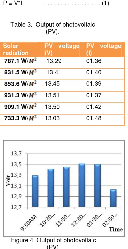
P = V*I . . . (1)
Table 3. Output of photovoltaic (PV).
Solar radiation
PV voltage (V)
PV voltage (I)
787.1 W/ 13.29 01.36 831.5 W/ 13.41 01.40 853.6 W/ 13.45 01.39 931.3 W/ 13.51 01.37
909.1 W/ 13.50 01.42
733.3 W/ 13.03 01.48
Figure 4. Output of photovoltaic (PV)
The figure. 4. Explains the voltages that measured from PV Cell at open connection (no load) at various time. It can be seen that the peak voltage that can be produced by the PV cell is during 12:00am until 2:00pm.
Battery Bank
In this research, the type of battery is Panasonic, each battery has DC voltage at 6V, 1.3 Ah. The battery bank is a set of batteries that connected in parallel, therefore able to supply 2.6Ah.as in the figure . 5 .
CHARGE CONTROLLER
-+
+
-+
-+
-Figure 5. Battery Bank in parallel.
The General rule to calculate the average charge time:
Take Amp/hour rating of the battery and Divide by the charger rating (in amperes) and then add about 10% for the extra time to top off the battery.
Power Battery :-
Voltage = 6 volt DC , 2.6 Ah
Power (watts) = Voltage (V) x Current drawn in Amps (I)
Wh
A
P
6
2
.
6
15
.
6
Daily PV output needed: 15.6 Wh 30 % PV Power Loss Estimation: 30 % x 15.6Wh = 5.2Wh
Average sun hours / day 6 hours Minimum system size
As show in the figure 6. There is a gradual change of voltage in the battery bank reach approximately 6.5 volts of the battery bank, and increasing from at 9:30 Am until afternoon at 2:00 Pm start from around 20% until 100% for about 5 hours.
Figure 6. Overcharge volt battery.
Figure 7. Discharger Volt Battery. For this test, a lamp (12 volts, 32 watts) is used that able to drain the battery bank quickly.
In the diagram figure. 7. Shows the voltage decreases when the load is connected to the device. The load used was capable to drain the battery from 6 vdc to lower than 2.3 vdc within around 5 hours.
Photovoltaic Charger System
Figure. 7. Photovoltaic systems consist of solar panels and a battery bank. The lifetime of the panels is typically 20 to 25 years, which is considered the lifetime of the total system. The battery stores the power from the sun and is used when the sun isn’t shining or during cloudy weather. Two Types of batteries can be used, deep cycle and starter batteries. The deep cycle batteries are more efficient and most commonly used, the charge controller regulates the current added to and drawn from the battery in order to maximize the battery lifetime and for user safety.
Because photovoltaic systems produce a direct current.
Figure 8. Experiment To Charge Mobile Phone Battery System.
System is designed so the battery bank and the PV Cells are operate and maintained safely. Here are the system characteristics:
1. When the Battery voltage is more than 4.8 volts, the op-amp outputs 5 volts, that will drive switching device (in this case MOSFET) to turn on. Any connected load to the port is absorbing current from the battery.
2. On the other hand, whenever battery voltage goes to or lower than 2.3 volts, the op-amp outputs 0 Volts, in this case the MOSFET will not disconnect any load to ground, thus, no currents are available for the connected load. This condition will give opportunity for the battery to be recharged again and avoid being excessively discharged that will damage the battery.
Controller
PV Battery
Bank
3. Consequently, when the battery voltage reaches 4.8 volts, the op-amp outputs 5 volts again and MOSFET is supplied by enough current to connect the load to the ground and enables current to flow from battery to load. This state remains the same for the battery voltage above 4.8 volts.
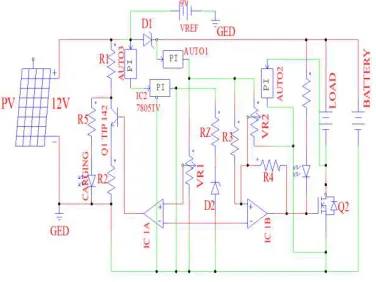
Above characteristics are operated by circuit that shown at Figure 9.
Figure 9. Charge Controller Circuit.
Figure. 9. Shows the overcharge controller is a comparator circuit where it will limit the charging values so that the battery will be safely recharged. The following calculation is an example to calibrate the Rv1 so that the overcharge maximum voltage is 6.5.
……….(2)
VR1out = 50.7k
The output of comparator circuit is then control transistor circuit. And the Transistor analysis :
Where, = 6V, VB = 4V, and assume = 10mA, Ic = 300mA. Thus
………...(3)
from equation (1)
.
…………..(4)
For the discharge controller, based on Schmitt Trigger, given values for = 5 and
= 0, thus,
With given value for = 5 and = 0
The value given is ( ) = 2.5
And this value then gives =R3=1K and =R4=2K
Testing Configuration
As the schematic of Photovoltaic charger is implemented as a whole system, included the wirings, here are the measurement purposes:
1. Measuring the controller capability in overcharged state.
3. Real-time PV charge operations (charging time, no light condition, and charging specific battery). To perform those measurements, Figure 10 is the diagram of the measurement plan.
Figure 10. Measurement diagram.
Overcharge Test
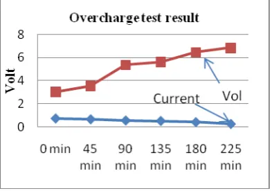
From the test data, the graphic in figure 11 shows that there is a gradual change of voltage in the battery bank and the current, that flow to the battery bank is also decreasing relatively linear which then stop recharging at the desired value by prior calibration of voltage divider for overcharge controller.
Figure 11. Overcharge test result.
The graph figure 11. Contains two line graphs. The dotted line graph is the voltage rise at battery bank during recharging process. The voltage is rising from 2 volts to 6.5 volts within approximately 6 hours. Meanwhile, the line graph with triangle dot displays the current flow from PV to battery
bank. It can be seen that during recharging process the current is gradually decreased from 700mA to 100mA, it means that over the time of charging, the current is starting to saturated due to balanced voltage between PV and battery bank.
Moreover, it can be seen that the recharging state is initiating to maintain the peak voltage at approximately 6.5 volts of the battery bank. The voltage will remain relatively at 6.5 volts by appropriate current that slowly decreased until no currents are being drawn by battery bank.
Discharge test
Based on actual values of the test, below is the graphic view of test results table. Voltage on PV Cell is now removed. Due to the fact that SCHMITT TRIGGER has two voltages to distinguish ON and OFF states, there are two procedures that must be follow to measure the ON voltage ( ) and th OFF voltage ( ).
First is to reveal the by doing the following steps. The Load will be simulated by a lamp (12 volts, 32 watts) that able to drain the battery bank quickly. The voltage and current between Battery Bank and load will be recorded during the test. The measurement diagram is shown below.
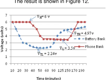
The result is shown in Figure 12.
Figure 12. Discharge control using Schmitt Trigger.
In figure 12, there are two line graphs, the discrete-like and logarithmic line graphs. The first graph, the discrete-like line graph, to the disconnected ground at the load. The component that made the load connected or disconnected to the ground is NMOS transistor.
The second line graph, the logarithmic one, is the voltage at NMOS gate pin that taken from SCHMITT TRIGGER output. It shows that NMOS transistor will be in saturated mode when the voltage that flow at its gate is higher than 2 volts, otherwise it will be in cut off mode
Real Time test
This test contains 3 different tests that generally will test the system in the specific conditions and as alternative energy resource. Here are the test results :-
1. During daytime condition with clear sky at Malang 9 am to 2 pm, the PV can supply sufficient 14 volts and 180 mA to 320 mA current that appropriate to charge 6 volts battery. When the sunlight is shaded by clouds, the voltage and current dropped significantly to 6-8 volts and below 100
mA current, which are not capable to slower than the proprietary charger.
CONCLUSION
The design of charging battery mobile phone was achieved successfully. The circuit design was able to convert the solar panel to charge the battery of mobile phone. From the design of Photovoltaic charger as the prototype, which implements operational amplifier to perform as overcharge controller using comparator circuit.
This paper presents the experiment result of a solar energy system, and this system have two modes, mode one solar energy to charging storage battery, second mode from storage battery to charger battery mobile phone. These results are very useful for charging battery form sun light and it’s more economical and Environmentally friendly and the advantage of the system compared to charger mobile phone ac to dc. And this solution for the electrification of remote areas.
From the design of Photovoltaic charger as the prototype, which implements operational amplifier to perform as overcharge controller using comparator circuit and discharge controller using Schmidt Trigger circuit is suitable to create automatic solar charger.
overcharge controller is not discrete graphic, but more logarithmic.
On the other test, the discharge test, shows that the Schmidt Trigger is able to protect the battery bank from being discharged excessively. The test shows that the load will be disconnected whenever the battery bank voltage reached 2.24 volts and safely turn on the load again at 4.97 volts.
REFERENCES
[1] Opara ,E.Efemena and Felix Egbujo.,2011, “Solar Solution For Mobile Charging Centers In Nigeria”, EBSCO HOST
International Journal
of Academic Research
, Vol 3 no 1,
418-426.
[2] Saleh, Ibrahim., 2006, “Prospects of renewable energy in Libya”,
Faculty of
Engineering, Al-Fateh University
,Libya.[3] Nema and Rangnekar, 2010, “ Study about PV-solar / wind hybrid energy system for GSM/CDMA” , International Journal Of Energy and Environment., Vol 1, 359-366.
[4] 397 I. M. Saleh Ibrahim Al-Jadi and N. M., 2005, Krema described the Photovoltaic in Libya application ,and evaluation”,