A New DOA Estimation Technique Based on
Subarray Beamforming
Nanyan Wang, Panajotis Agathoklis, and Andreas Antoniou
, Life Fellow, IEEE
Abstract—A new direction-of-arrival (DOA) estimation tech-nique using subarray beamforming is proposed. Two virtual subarrays are used to form a signal whose phase relative to the reference signal is a function of the DOA. The DOA is then estimated based on the computation of the phase shift between the reference signal and its phase-shifted version. Since the phase-shifted reference signal is obtained after interference rejec-tion through beamforming, the effect of cochannel interference on the estimation is significantly reduced. The proposed technique is computationally simple, and the number of signal sources detectable is not bounded by the number of antenna elements used. Performance analysis and extensive simulations show that the proposed technique offers significantly improved estimation resolution, capacity, and accuracy relative to existing techniques.
Index Terms—Beamforming, direction of arrival (DOA), estima-tion.
I. INTRODUCTION
S
MART antennas have been widely used in many applica-tions such as radar, sonar, and communication systems. The performance of smart antennas relies heavily on the accurate estimation of the direction of arrival (DOA) of each signal, and various techniques for DOA estimation have been proposed [1]–[12].The most commonly used techniques are multiple signal classification (MUSIC) [3], [4], estimation of signal param-eters via rotational invariance technique (ESPRIT) [5]–[7], and their variations [8], [9]. These subspace-based techniques lead to an acceptable DOA estimation if the number of signal sources is less than the number of antenna elements. In the case where the total number of interfering and target signal sources is larger than the number of antenna elements, only some of the DOAs of the signals can be properly estimated. In MUSIC-class techniques, the DOAs are determined by finding the directions for which their antenna response vectors lead to peaks in the MUSIC spectrum formed by the eigenvectors of the noise subspace. The maximum number of DOAs detectable, i.e., the capacity of DOA estimation technique, is equal to the
Manuscript received December 1, 2004; revised September 7, 2005. This work was supported by the Natural Sciences and Engineering Research Council of Canada and Micronet, NCE Program. The associate editor coor-dinating the review of this manuscript and approving it for publication was Dr. Daniel Fuhrman.
N. Wang is with PMC-Sierra, Inc., Burnaby, BC V5A 4X1, Canada, and the Department of Electrical and Computer Enginering, University of Victoria, Victoria BC V8W 3P6, Canada (e-mail: [email protected]; nanyan_wang@ pmc-sierra.com).
P. Agathoklis and A. Antoniou are with the Department of Electrical and Computer Engineering, University of Victoria, Victoria, BC V8W 3P6, Canada (e-mail: [email protected]; [email protected]).
Digital Object Identifier 10.1109/TSP.2006.877653
rank of the reciprocal subspace of the selected noise subspace. Thus, the capacity of DOA estimation using MUSIC is no more than 1 where is the number of antenna elements in the antenna array [13]. For ESPRIT-class techniques, two subarrays are used to obtain two signal subspaces such that the eigenvectors of one signal subspace relative to the eigenvectors of the other are rotated in terms of the DOAs of the signals. The DOAs are then estimated by computing the rotation matrix. As a result, the capacity of DOA estimation using ESPRIT-class techniques is bounded by the number of antenna elements in the subarrays [9], [14]. This limits the application of subspace-based techniques to cases where the number of signal sources is less than the number of antenna elements. In addition, these techniques require subspace estimation and eigendecomposition which entail high computational com-plexity [7], [15], [16], thereby limiting their use to applications where fast DOA estimation is not required. Further, using these techniques in the presence of multiple signal sources, the DOAs of the target signals and interference are all estimated, and as a consequence, these techniques cannot identify which signal source corresponds to which estimated DOA.
In some applications such as wireless communication sys-tems, a pilot signal (or decision-directed signal) is usually available [17]. In active radar and sonar systems, the signal received from a target is a reflection of the known transmitted signal. Maximum likelihood (ML) techniques [10]–[12] have been developed to exploit such signals in the DOA estimation. In these techniques, the most likely DOAs are estimated so that the samples of received signals are matched to the known signals. The maximization of the log-likelihood function is a nonlinear optimization problem that requires multidimensional search and thus entails a very large amount computation. The ML algorithm proposed in [10] transforms the multidi-mensional search problem into an iterative one-dimultidi-mensional search problem. This technique needs another DOA estimation technique such as MUSIC and ESPRIT to provide initial esti-mation; further, there is no guarantee of global convergence. In [11], another decoupled ML algorithm is described. It is computationally more efficient and can estimate DOAs in the presence of interference or jamming signals. A spatial signature based ML DOA estimation technique is described in [12]. The DOAs of known signals are computed based on ML estimation of their corresponding spatial signatures. The capacity of DOA estimation of this technique is larger than the number of antenna elements and it can deal with correlated signals. It requires that the noise be spatially and temporally white; therefore, the performance of this technique is sensitive to directional interference, which is present in many applications.
In this paper, a new subarray beamforming-based DOA (SBDOA) estimation technique that uses a reference signal (pilot or decision-directed signal) is proposed. The major differ-ence between the proposed SBDOA estimation technique and existing techniques is that in the SBDOA estimation technique, the target DOA is estimated after interference rejection using beamforming. In existing techniques, the DOA estimation is based on either computing the spatial signatures (or antenna response vectors) or the signal subspace spanned by the spatial signatures. Since the information pertaining to spatial signa-tures exists only in the received signals before beamforming, none of existing techniques can estimate a DOA after beam-forming. As a result, a DOA is estimated in the presence of many other signals from sources other than the target one and, therefore, the performance of DOA estimation algorithms is significantly degraded by the interference.
In the proposed SBDOA estimation technique, the target DOA is estimated from the phase shift introduced in the target signal by subarray beamforming, which is a function of the target DOA. Since the phase shift is estimated after subarray beamforming, all signals and interference other than the target one can be efficiently rejected before DOA estimation. Thus their interference on the DOA estimation is reduced. In this way, the estimation resolution and accuracy of the proposed SBDOA technique are better than those of existing techniques. The capacity of DOA estimation using the proposed SBDOA technique can be far larger than the number of antenna ele-ments. Since subspace estimation, eigendecomposition, and multidimensional optimization are not required in the SBDOA technique, as is the case in other DOA estimation techniques, the SBDOA technique is computationally simpler and can be easily implemented in terms of hardware. Further, the use of a reference signal that can be either a pilot signal or a deci-sion-directed signal enables the proposed SBDOA technique to identify which signal source corresponds to which estimated DOA.
The organization of this paper is as follows. In Section II, the signal model considered is described. The subarray signal for-mation, subarray beamforming, and DOA computation of the proposed SBDOA technique are presented in Section III. A per-formance analysis of the new DOA estimation technique is pro-vided in Section IV. In Section V, numerical results pertaining to the resolution, capacity, and accuracy for the SBDOA tech-nique and comparisons with existing techtech-niques are presented. Conclusions are drawn in Section VI.
II. SIGNALMODEL
The SBDOA technique uses the same antenna array geometry as that used in ESPRIT-class techniques. The antenna array is decomposed into two equal-sized subarrays such that for each element in one subarray, there is a corresponding element in the other subarray displaced by a fixed translational distance. Below, we discuss only the commonly used uniform linear array (ULA) since the SBDOA technique can be easily applied to other kinds of antenna arrays.
Consider an -element ULA with adjacent element spacing deployed at a base station. Let angle in radians denote the
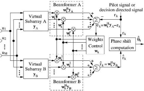
Fig. 1. Block diagram of the SBDOA system.
DOA of the signal from source . The -dimensional column vector , known as the antenna-array response vector is given by
(1)
where and is the wavelength.
In this paper, we assume that signals from different sources are uncorrelated or have negligible correlation with each other. If there are signal sources and unknown interference sources, the received signal at the antenna array after down-con-verting to baseband can be represented by the -dimensional vector
(2)
where for is a target signal component,
for is an unknown interference
component, and is a spatially stationary background noise vector with zero mean and cross-covariance
(3)
where is the identity matrix.
III. SUBARRAYBEAMFORMING-BASEDDOA ESTIMATION
the same source in is a function of the DOA. The two sub-array signals are then fed into beamformers A and B. The weight vector is obtained by minimizing the mean-square error (MSE) between the output signal of beamformer A and the reference signal . Using the weight vector obtained from beamformer A, the subarray signal is weighted and com-bined in beamformer B. It will be shown that the output of beam-former B, i.e., , is an optimum estimation of the phase-shifted reference signal and, further, the phase of relative to that of the reference signal is a function of the target DOA, . Fi-nally, the estimation of the target is obtained based on the computation of the phase shift between the phase-shifted refer-ence signal and the reference signal .
The proposed DOA estimator is described in detail in Section III-A–C.
A. Subarray Signal Formation
As mentioned in Section II, the SBDOA technique requires that each pair of elements in the two subarrays be displaced by a fixed translational distance. In the case where a ULA is deployed at the receiver, two kinds of antenna element multi-plexing geometries can be used to obtain two virtual subarrays: maximum overlapping subarrays (MOSs) [18] or conjugate sub-arrays (CSs) [9].
1) Use of Maximum Overlapping Subarrays: Consider an -element ULA deployed at a receiver. MOSs have two sets of ( 1)-element virtual subarrays, A and B. Subarray A con-sists of the first 1 elements of the -element antenna array deployed at the receiver and subarray B consists of the last elements. If
(4)
represents the down-converted baseband signals received by the th element of the antenna array for , then the two ( 1)-dimension signal vectors of subarrays A and B are given by
(5) (6)
respectively. If we let ,
subarray signals and can be written as
(7)
(8)
where vectors and are the background noise at sub-arrays A and B, respectively. It can be seen from (7) and (8) that using MOSs, the phase shift between the th signal components
of and is an angle , which is a
function of the DOA, , of the th component.
2) Use of Conjugate Subarrays: The use of CSs was origi-nally proposed in conjugate ESPRIT (C-SPRIT) in [9]. In CSs, each virtual subarray has the same number of elements as the
antenna array deployed. It has been shown in [9] that by using CSs, C-SPRIT can provide higher resolution and can estimate one more DOA than conventional ESPRIT using MOSs. This is due to the fact that CSs have one more antenna element in each subarray than MOSs. Similarly, as will be shown, using the SBDOA technique, CSs lead to more efficient subarray beam-forming and provide higher estimation accuracy of the DOA than MOSs. However, CSs have limited applications due to the fact that the phase-shift relationship between each pair of signal components in the two signals and exists only when
is real.
Consider an -element ULA deployed at a receiver. CSs have two sets of -element virtual subarrays. The -dimen-sion signal vectors of subarray A and of subarray B are
(9)
(10)
respectively. If is real, then
(11)
From (9) and (11), it can be seen that using CSs, the phase shift between the th signal components of and is an
angle , which is a function of the DOA, ,
of the th component.
3) Unifying Signal Models for MOSs and CSs: If we let the number of subarray elements in the above analysis be , then a unified description of the SBDOA technique is obtained which applies to the MOSs geometry if or to the CSs geometry if . Thus we can write
(12)
(13)
where is the subarray antenna
response vector. The phase-shift factor between the th compo-nents of signals and which are from the th signal is given by
for MOSs
for CSs (14)
B. Subarray Beamforming
of beamformer B by using beamforming weights obtained from beamformer A.
Consider the case where for is the target DOA to be estimated. The purpose of beamformer B is to reject all the signal and interference components from sources other than source and obtain an optimum estimation of the phase-shifted reference signal at the output of beamformer B. This can be achieved by solving the optimization problem
(15)
In (15), is the reference signal for signal . It can be the pilot signal in the pilot channel-aided beamforming [19], [20] or the decision-directed signal in the decision-directed signal-based beamforming techniques [21], [22]. Since the phase-shift factor
is unknown, the phase-shifted reference signal
is not available. Thus, the weight vector cannot be obtained directly from (15), but it can be obtained from the optimum weights of beamformer A as shown in Proposition 1.
Proposition 1: The weight vector that solves the problem in (15) is the same as the weight vector that solves the op-timization problem
(16)
i.e., finding the optimum weight vector for beamformer A where the MSE between the output signal of beamformer A and the known reference signal is minimized.
Proof: The optimal weight vector in (16) can be readily obtained in closed form as
(17)
where
(18) (19)
are the autocorrelation matrix of the input signal and the cross-correlation vector between the input signal and the refer-ence signal , respectively.
The optimum weight vector in (15) can be obtained in closed form as
(20)
where
(21) (22)
Substituting (12) and (13) into (18) and (21), respectively, yields
(23)
(24)
where is the power of a target signal component for and is the power of an interference component
for is an identity matrix and and
are the variances of background noise vectors and in subarrays A and B, respectively. Based on the assumption that the background noise is spatially stationary, we have
(25)
and hence it follows that
(26)
Substituting (12) and (13) into (19) and (22), respectively, it can be shown that
(27)
where is the power of the reference signal . From (26) and (27), we have
(28)
Thus, Proposition 1 is proved.
Since , the weight vector can then be obtained by solving the problem in (16) using existing algorithms such as the direct approach [19] using (17) or the least mean square algorithm [20], [22].
C. Computation of DOA
Let denote the output signal of
beam-former B. Since is an optimum estimation of the phase-shifted reference signal in the MMSE sense, it can be written as
(29)
which represents the reference signal shifted by plus an es-timation error. Let
denote vectors with samples of the reference signal and the esti-mated phase-shifted reference signal in a snapshot interval, re-spectively. If denotes an estimate of , it can be computed using the least square method such that the square error between the two signal vectors and is minimized, i.e.,
(32)
If , where , the optimization problem
in (32) can be written as
(33)
This optimization problem can be easily solved using the La-grange multipliers method and the solution can be obtained as
(34)
which is the angle of the complex inner product of the reference signal vector and its phase-shifted version. In light of (14), an estimation of the target DOA can then be obtained as
for MOSs
for CSs (35)
In the proposed technique, the DOA is estimated from the phase shift between the reference signal and its phase-shifted version. Thus, the capacity of DOA estimation is no longer bounded by the number of antenna elements as in existing tech-niques. Most importantly, the DOAs are estimated after inter-ference rejection through subarray beamforming and, therefore, the effect of cochannel interference on DOA estimation is re-duced, as will be verified through performance analysis and sim-ulations in the next two sections.
IV. PERFORMANCEANALYSIS
In this section, the performance of the SBDOA technique will be analyzed. Proposition 2 below shows that the SBDOA esti-mator is an asymptotically consistent estiesti-mator. In Proposition 3, the probability density function and the variance of the esti-mated DOA using the SBDOA technique are derived. Based on Proposition 3, the effects of snapshot length and signal-to-(in-terference plus noise) ratio (SINR) on DOA estimation can be investigated.
Proposition 2: The SBDOA estimator is an asymptotically consistent estimator, i.e.,
(36)
Proof: Let
(37)
denote the estimation error vector between the output of beam-former B and its desired response in a snapshot interval . Using (29), we have
(38)
and hence
(39)
Substituting (39) into (34), the estimated phase shift can be written as
(40)
If
(41)
denotes the estimation error of the phase shift of target source , then we have
(42)
When , we have
(43)
(44)
where denotes expectation. Substituting (43) and (44) into (42) yields
(45)
It has been shown in Section III-B that and that the weight vector obtained from beamformer A is the optimal solu-tion in the sense of minimizing (15). In light of the corollary to the principle of orthogonality of Wiener filters [24], the estimate of the desired response at the output of beamformer B and the corresponding estimation error (29) are orthogonal to each other. Thus, we have
Substituting (46) into (45) yields
(47)
From (35), we have
for MOSs
for CSs
(48)
and by using (47)
for MOSs
for CSs (49)
Thus, Proposition 2 is proved.
Proposition 2 shows that the SBDOA estimator is an asymp-totically consistent estimator such that the DOA estimation error will approach zero as the snapshot length approaches infinity. In many applications, a long snapshot length may be imprac-tical and it is, therefore, important that a DOA estimator be able to track fast-changing DOAs based on limited signal samples. Proposition 3 gives the probability density function and variance of the estimated DOA, which will be used to evaluate the effect of snapshot length on the estimation accuracy and capacity of the proposed technique.
Proposition 3: The probability density function and the vari-ance of the estimated DOA using the SBDOA technique are given by
(50)
(51)
respectively, where
for MOSs
for CSs (52)
and is the probability density function of a chi-squared dis-tributed random process whose degrees of freedom are equal to the snapshot length and are probability density func-tions of two zero-mean Gaussian random processes. They are given by
(53)
(54)
(55)
where
(56)
and is the power of the reference signal , is the power of the error signal at the output of beamformer A, and
is the SINR at the output of beamformer A. Proof: From (42), we have
(57)
If we let
(58) (59)
be the real and imaginary components of , respec-tively, the estimation error of the phase shift in (57) can be written as
(60)
Assuming that has zero mean, it can be derived from (39) and (46) that
(61)
where
(62) (63)
denote the powers of the reference signal and the estimation error, respectively.
From (46), we have
(64)
Hence
(65)
i.e., random processes and have zero means. As-suming that and are two independent Gaussian pro-cesses with equal variances, it can be shown that
If we let
(67)
(68)
(69)
the estimation error of the phase shift in (60) assumes the form
(70)
Since is also a Gaussian process with
(71)
(72)
random process is chi-squared distributed with degrees of freedom. Its probability density function is given by (53). The random variables and are the sums of Gaussian variables and thus they are still Gaussian distributed. It can be shown that
(73)
i.e., and have zero means. The variances of and can be readily derived as
(74)
It can be shown that
(75)
(see Appendix A), i.e., the error signal at the output of beamformer A has the same power as error signal at the output of beamformer B. If we let
(76)
be the SINR of the signal at the output of beamformer A, sub-stituting (75) and (76) into (74) yields
(77)
and the probability density functions of and are given by (54) and (55), respectively.
The probability density function of can now be derived as (see Appendix B for details)
(78)
and from (48), we have
for MOSs
for CSs
(79)
The probability density function of is thus obtained as
(80)
where is the derivative of function with re-spect to . It can be written as
(81)
The variance of the estimated can then be obtained as
(82)
Thus, Proposition 3 is proved.
Plots of the probability density function of the estimated DOA in degrees for different snapshot lengths and SINRs at the output of beamformer B are illustrated in Figs. 2 and 3. It can be seen from Fig. 2 that a higher estimation accuracy can be obtained using a longer snapshot length. This is consistent with Proposi-tion 1. Similarly, Fig. 3 shows that the a higher SINR will lead to a better estimation accuracy. Thus, the number of sources detectable using the SBDOA technique is not limited by the number of antenna elements; and the accuracy of DOA esti-mation can be improved by an efficient interference rejection through subarray beamforming. Therefore, high capacity and improved resolution of DOA estimation can be achieved using the SBDOA technique.
V. SIMULATIONRESULTS
Fig. 2. Effect of the snapshot lengthLon the estimated DOA (plots of proba-bility density function for = 5dB,L = 10; 100; 1000, and the target DOA = 0 ).
Fig. 3. Effect of the SINR at the output of beamformer A on the es-timated DOA (plots of probability density function for = 1; 5; 10dB,
L = 100, and the target DOA = 0 ).
between two DOAs that can be resolved by the estimation tech-nique. The term capacity is used to denote the maximum number of signal sources that a DOA estimation technique is capable of detecting. In Examples 1 and 2, the resolution and capacity of the DOA estimation using the SBDOA technique and existing techniques will be compared and illustrated. In Example 3, the effects of snapshot length and strength of interference on the es-timation capacity and accuracy will be investigated.
A. Example 1: Resolution of DOA Estimation
Example 1 deals with a case where the DOAs of five signal and interference sources are closely distributed. A six-element ULA with a spacing of deployed at the receiver was considered. Three target signal components with a pilot signal and two unknown interference components were assumed to
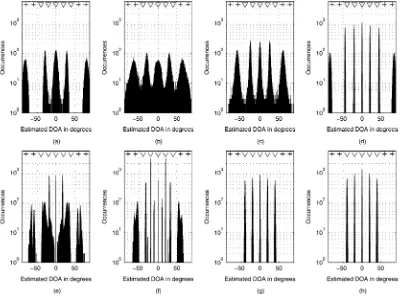
be received at the antenna array with equal power. It was fur-ther assumed that the DOAs of the target signal components were at 2 , 0 , and 2 . The DOAs of the interference compo-nents were at 4 and 4 . The information bit-to-background noise (not including interference components) power spectral density ratio of the received signal was set to 15 dB. Ten thousand simulation runs were performed. For each run, the DOA was obtained using MUSIC [4], ESPRIT [6] using MOSs, ESPRIT using CSs (C-SPRIT) [9], Capon [1], the de-coupled ML (DEML) algorithm [11], the spatial signature based ML (SSBML) estimation technique [12] with the assumption that the delays are known, and the proposed SBDOA technique using MOSs or CSs were used to obtain the DOAs. A snap-shot length of 200 samples was used for all techniques to as-sure a fair comparison. The subarray beamforming weights for the SBDOA technique were obtained by applying the direct ap-proach using (17). The histograms obtained for the various tech-niques are shown in Fig. 4. Each histogram depicts the number of occurrences of each estimated DOA as a function of DOA in degrees. The actual DOAs of different signals are marked at the top of each figure by triangles. In Fig. 4(a)–(d), only one or two peaks can be seen in the histogram plots, indicating that existing techniques do not lead to satisfactory results when the signals’ DOAs are very close. In contrast, the histogram plots in Fig. 4(e)–(f) show three peak values, indicating that using the proposed SBDOA technique, all three DOAs are success-fully estimated. This confirms that the SBDOA technique leads to a better resolution than existing techniques. Further, it can be seen by comparing Fig. 4(e) and (f) that the resolution of the SBDOA technique using CSs is better than that obtained using MOSs. This is due to the fact that CSs have one more element than MOSs in each subarray, which will lead to higher SINR at the beamformer output for CSs. This is consistent with Propo-sition 3, where it was shown that an increase in SINR leads to better estimation accuracy.
B. Example 2: Capacity and Accuracy of DOA Estimation
Fig. 4. Example 1: Comparison of the resolution of DOA estimation for signal sources that are closely distributed. A snapshot length of 200 samples was used for all techniques. The vertical axis represents the number of times that a certain value of estimated DOA was obtained. The triangles at the top indicate the actual DOAs of 3 target signal components at 2 , 0 , and02 . The pluses at the top indicate the DOAs of two interference components at 4 and04 . (a) Capon, (b) MUSIC, (c) ESPRIT using MOMs, (d) ESPRIT using CSs, (e) DEML, (f) SSBL, (g) SBDOA technique using MOSs, (h) SBDOA technique using CSs.
improvement will be further illustrated by means of simulations considering more signal sources in Example 3. The capacity of DOA estimation for different techniques is summarized in Table I.
C. Example 3: Effects of Snapshot Length and Interference on Estimation Capacity and Accuracy
In Example 3, the snapshot length for subarray beamforming and DOA computation was set to different values-20, 30, 50,100, and 1000-and the number of signal sources varied from 4 to 20. The DOA of the target signal with pilot was fixed at 0 and the DOAs of unknown signals from other sources were randomly distributed from 90 to 90 in each simulation run. All other simulation conditions were kept the same as in Ex-ample 1. The root mean square error (RMSE) of the estimated target DOA averaged over 10 000 simulation runs versus the number of signal sources and the snapshot length are illustrated in Fig. 6. As can be seen, using a small snapshot length such as 50, the proposed SBDOA technique leads to an RMSE of less than 4 in the presence of 20 equal-powered signals. This demonstrates the fast DOA tracking capability of the SBDOA technique and further confirms that its estimation capacity can be larger than the number of antenna elements. It can also be
seen in Fig. 6 that the RMSE increases as the number of signal sources increases. This is due to the fact that in the presence of a large number of signal sources, the interference cannot be effectively rejected using beamforming. In addition, the RMSE decreases as the snapshot length increases. This confirms the performance analysis in Section IV that the capacity and accu-racy of the DOA estimation can be improved by increasing the snapshot length.
VI. CONCLUSION
Fig. 5. Example 2: Comparison of the capacity of DOA estimation when the number of signal and interference sources is larger than the number of antenna elements. A snapshot length of 200 samples was used for all techniques. The vertical axis represents the number of times that a certain value of estimated DOA was obtained. The triangles at the top indicate the actual DOAs of five target signal components at040 ; 020 , 0 , 20 , and 40 . The pluses at the top indicate the DOAs of four interference components at080 ; 060 , 60 , and 80 . (a) Capon, (b) MUSIC, (c) ESPRIT using MOMs, (d) ESPRIT using CSs, (e) DEML, (f) SSBL, (g) SBDOA technique using MOSs, (h) SBDOA technique using CSs.
TABLE I
CAPACITY OFDOA ESTIMATION FORDIFFERENTTECHNIQUES
APPENDIXA DERIVATION OF(75)
The power of the error signal at the output of beam-former A is given by
(83)
Substituting (12) into (83) yields
(84)
Fig. 6. Example 3: Root mean square error of the estimated DOA for different snapshot lengthLand number of signal sourcesK.
The power of the error signal at the output of beamformer B is given by
Substituting (13) into (85), we have
(86)
From (26) and (28), it follows that
(87)
APPENDIXB DERIVATION OF(78)
If , it can be shown that and are independent. Their joint probability density function is given by
(88)
Assuming that
(89) (90)
and transforming the variables into using the theorem of transformation of variables [25], the probability
den-sity function can be obtained as
(91)
(92)
It can be shown that if is independent of , then will be inde-pendent of . The probability density function
is thus given by
(93)
(94)
ACKNOWLEDGMENT
The authors wish to thank the reviewers for helpful comments and suggestions.
REFERENCES
[1] J. C. Liberti and T. S. Rappaport, Smart Antennas for Wireless Com-munications: IS-95 and Third Generation CDMA Applications. En-glewood Cliffs, NJ: Prentice-Hall, 1999.
[2] L. C. Godara, “Application of antenna arrays to mobile communi-cations—II: Beam-forming and direction-of-arrival considerations,”
Proc. IEEE, vol. 85, no. 8, pp. 1195–1245, Aug. 1997.
[3] A. J. Barabell, “Improving the resolution performance of eigenstruc-ture-based direction-finding algorithms,”Proc. Int. Conf. Acoustics, Speech, Signal Processing (ICASSP) 1983, vol. AP-34, pp. 336–339, Mar. 1983.
[4] R. O. Schmidt, “Multiple emitter location and signal parameter estima-tion,”IEEE Trans. Antennas Propag., vol. AP-34, pp. 276–280, Mar. 1986.
[5] R. Roy, A. Paulrajand, and T. Kailath, “Direction-of-arrival estimation by subspace rotation methods—ESPRIT,”Proc. Int. Conf. Acoustics, Speech, Signal Processing (ICASSP) 1986, vol. AP-34, pp. 2495–2498, Apr. 1986.
[6] R. Roy and T. Kailath, “ESPRIT-estimation of signal parameters via rotational invariance techniques,”IEEE Trans. Acoust., Speech, Signal Process., vol. 37, no. 7, pp. 984–995, Jul. 1989.
[7] G. Xu, S. D. Silverstein, R. H. Roy, and T. Kailath, “Beamspace ES-PRIT,”IEEE. Trans. Signal Process., vol. 42, no. 2, pp. 349–356, Feb. 1994.
[8] M. L. McCloud and L. L. Scharf, “A new subspace identification al-gorithm for high-resolution DOA estimation,”IEEE Trans. Antennas Propag., vol. 50, pp. 1382–1390, Oct. 2002.
[9] N. Tayem and H. M. Kwon, “Conjugate ESPRIT (C-SPRIT),”IEEE Trans. Antennas Propag., vol. 52, pp. 2618–2624, Oct. 2004. [10] J. Li and R. T. Compton, “Maximum likelihood angle estimation for
signals with known waveforms,”IEEE. Trans. Signal Process., vol. 41, no. 9, pp. 2850–2862, Sep. 1993.
[11] J. Li, B. Halder, P. Stoica, and M. Viberg, “Computationally efficient angle estimation for signals with known waveforms,”IEEE. Trans. Signal Process., vol. 43, no. 9, pp. 2154–2163, Sep. 1995.
[12] A. L. Swindlehurst, “Time delay and spatial signature estimation using known asynchronous signals,”IEEE. Trans. Signal Process., vol. 46, no. 2, pp. 449–461, Feb. 1998.
[13] C. T. Chiang and A. C. Chang, “DOA estimation in the asynchronous DS-CDMA system,” IEEE Trans. Antennas Propag., vol. 51, pp. 40–47, Jan. 2003.
[14] Y. Wang and J. R. Cruz, “Adaptive antenna arrays for cellular CDMA communication systems,” inProc. Int. Conf. Acoustics, Speech, Signal Processing (ICASSP) 1995, Apr. 1995, vol. 3, pp. 1725–1728. [15] P. Comon and G. H. Golub, “Tracking a few extreme singular values
and vectors in signal processing,”Proc. IEEE, vol. 78, pp. 1327–1343, Aug. 1990.
[16] G. H. Golub and C. F. V. Loan, Matrix Computation. Baltimore, MD: Johns Hopkins Univ. Press, 1996.
[17] T. Ojanpera and R. Prasad, Wideband CDMA for Third Generation Mo-bile Communications. Norwood, MA: Artech House, 1998. [18] V. C. Soon and Y. F. Huang, “An analysis of ESPRIT under random
sensor uncertainties,”IEEE. Trans. Signal Process., vol. 40, no. 9, pp. 2353–2358, Sep. 1992.
[19] J. Choi, “Pilot channel-aided techniques to compute the beamforming vector for CDMA systems with antenna array,” IEEE Trans. Veh. Technol., vol. 49, pp. 1760–1775, Sept. 2000.
[20] S. Lim, J. Lee, and J. Park, “Performance evaluation of adaptive beam-forming using pilot and traffic channel in CDMA2000 reverse link,” in
Proc. IEEE Veh. Technol. Conf., Sep. 2002, vol. 4, pp. 2154–2157. [21] A. L. Swindlehurst, S. Daas, and J. Yang, “Analysis of a decision
di-rected beamformer,”IEEE. Trans. Signal Process., vol. 43, no. 12, pp. 2920–2927, Dec. 1995.
[22] S. Tanaka, M. Sawahashi, and F. Adachi, “Pilot symbol-assisted deci-sion-directed coherent adaptive array diversity for DS-CDMA mobile radio reverse link,”IEICE. Trans. Fundamentals, vol. E80-A, no. 12, Dec. 1997.
[23] A. Klouche-Djedid and M. Fujita, “Adaptive array sensor processing applications for mobile telephone communications,”IEEE Trans. Veh. Technol., vol. 45, pp. 405–416, Aug. 1996.
[24] S. Haykin, Adaptive Filter Theory. Englewood Cliffs, NJ: Prentice-Hall, 1996.
Nanyan Wangreceived the B.E. and M.S. degrees in electrical engineering from Huazhong University of Science and Technology, Wuhan, China, in 1995 and 1999, respectively, and the Ph.D. degree in electrical engineering from University of Victoria, BC, Canada, in 2005.
He is currently with the research and development division of PMC-Sierra Inc., Burnaby, BC. His re-search interests are in the areas of signal processing as applied in wireless communications, smart antennas, and power systems.
Dr. Wang received the First-Class Invention Prize from the Wuhan municipal government in 1998.
Panajotis Agathoklisreceived the Dipl.Ing. degree in electrical engineering and the Dr.Sc.Tech. degree from the Swiss Federal Institute of Technology, Zurich, in 1975 and 1980, respectively.
From 1981 until 1983, he was with the University of Calgary as a Postdoctoral Fellow and part-time In-structor. Since 1983, he has been with the Depart-ment of Electrical and Computer Engineering, Uni-versity of Victoria, BC, Canada, where he is currently a Professor. He was a Visiting Fellow with the Swiss Federal Institute of Technology, Australian National University, and University of Perth, Australia. His fields of interest are in digital signal processing and its applications in control systems and communications.
Prof. Agathoklis received an NSERC University Research Fellowship. He has been member of the Technical Program Committee of many international conferences and served as the Technical Program Chair of the 1991 IEEE Pacific Rim Conference on Communications, Computers and Signal Processing and the 1998 IEEE Symposium on Advances in Digital Filtering and Signal Processing.
Andreas Antoniou(M’69–SM’79–F’82–LF’04) re-ceived the B.Sc.(Eng.) and Ph.D. degrees in electrical engineering from the University of London, London, U.K., in 1963 and 1966, respectively.
He taught at Concordia University from 1970 to 1983, serving as Chair of the Department of Elec-trical and Computer Engineering during 1977–1983. He was the founding Chair of the Department of Elec-trical and Computer Engineering, University of Vic-toria, BC, Canada, from 1983 to 1990, and is now Professor Emeritus. His teaching and research inter-ests are in the area of digital signal processing. He is coauthor of (with W.-S. Lu)Two-Dimensional Digital Filters(Berlin, Germany: Marcel Dekker, 1992) and author ofDigital Filters: Analysis, Design, and Applications(New York: McGraw-Hill, 1993) andDigital Signal Processing: Signals, Systems, and Fil-ters(New York: McGraw-Hill, 2005).
Prof. Antoniou is a Fellow of the Institution of Electrical Engineers, U.K. He was an Associate Editor of the IEEE TRANSACTIONS ONCIRCUITS ANDSYSTEMS