IPsec Virtual Private Network Fundamentals
By James Henry Carmouche, - CCIE No. 6085
...
Table of Contents | Index
An introduction to designing and configuring Cisco IPsec VPNs
Understand the basics of the IPsec protocol and learn implementation best practices Study up-to-date IPsec design, incorporating current Cisco innovations in the
security and VPN marketplace
Learn how to avoid common pitfalls related to IPsec deployment
Reinforce theory with case studies, configuration examples showing how IPsec maps to real-world solutions
IPsec Virtual Private Network Fundamentals provides a basic working knowledge of IPsec on various Cisco routing and switching platforms. It provides the foundation necessary to understand the different components of Cisco IPsec implementation and how it can be successfully implemented in a variety of network topologies and markets (service provider, enterprise, financial, government). This book views IPsec as an emerging requirement in most major vertical markets, explaining the need for increased information authentication, confidentiality, and non-repudiation for secure transmission of confidential data. The book is written using a layered approach, starting with basic explanations of why IPsec was developed and the types of organizations relying on IPsec to secure data transmissions. It then outlines the basic IPsec/ISAKMP fundamentals that were developed to meet demand for secure data transmission. The book covers the design and implementation of IPsec VPN architectures using an array of Cisco products, starting with basic concepts and proceeding to more advanced topics including high availability solutions and public key infrastructure (PKI). Sample topology diagrams and configuration examples are provided in each chapter to reinforce the fundamentals expressed in text and to assist readers in translating
IPsec Virtual Private Network Fundamentals
By James Henry Carmouche, - CCIE No. 6085
...
Table of Contents | Index
Copyright
About the Author
About the Technical Reviewers
Acknowledgments
Command Syntax Conventions
Introduction
Methodology
Who Should Read This Book?
How This Book Is Organized
Part I: Introductory Concepts and Configuration/Troubleshooting
Chapter 1. Introduction to VPN Technologies
Overview of Cryptographic Components
Public Key Encryption Methods
The IP Security Protocol (IPsec)
IKE and ISAKMP
Chapter 3. Basic IPsec VPN Topologies and Configurations
Site-to-Site IPsec VPN Deployments
Site-to-Site IPsec VPN Deployments and GRE (IPsec+GRE)
Hub-and-Spoke IPsec VPN Deployments
Remote Access VPN Deployments
Summary
Chapter 4. Common IPsec VPN Issues
IPsec Diagnostic Tools within Cisco IOS
Common Configuration Issues with IPsec VPNs
Architectural and Design Issues with IPsec VPNs
Summary
Part II: Designing VPN Architectures
Chapter 5. Designing for High Availability
Network and Path Redundancy
IPSec Tunnel Termination Redundancy
Managing Peer and Path Availability
Managing Path Symmetry
Load Balancing, Load Sharing, and High Availability
Summary
Chapter 6. Solutions for Local Site-to-Site High Availability
Using Multiple Crypto Interfaces for High Availability
Stateless IPsec VPN High-Availability Alternatives
Stateful IPsec VPN High-Availability Alternatives
Summary
Chapter 7. Solutions for Geographic Site-to-Site High Availability
Geographic IPsec VPN HA with Reverse Route Injection and Multiple IPsecPeers
Geographic IPsec VPN High Availability with IPsec+GRE and EncryptedRouting Protocols Dynamic Multipoint Virtual Private Networks
Summary
Chapter 8. Handling Vendor Interoperability with High Availability
Vendor Interoperability Impact on Peer Availability
Vendor Interoperability Impact on Path Availability
Vendor Interoperability Design Considerations and Options
Summary
Chapter 9. Solutions for Remote-Access VPN High Availability
IPsec RAVPN Concentrator HA Using the VCA Protocol
IPsec RAVPN Geographic HA Design Options
Summary
Chapter 10. Further Architectural Options for IPsec
IPsec VPN Termination On-a-Stick
In-Path Versus Out-of-Path Encryption with IPsec
Separate Termination of IPsec and GRE (GRE-Offload)
Summary
Part III: Advanced Topics
Chapter 11. Public Key Infrastructure and IPsec VPNs
PKI Background
PKI Components
Life of a Public Key Certificate
PKI and the IPSec Protocol SuiteWhere PKI Fits into the IPSec model
OCSP and CRL Scalability
Case Studies and Sample Configurations
Summary
Chapter 12. Solutions for Handling Dynamically Addressed Peers
Dynamic Crypto Maps
Tunnel Endpoint Discovery
Case StudyUsing Dynamic Addressing with Low-Maintenance Small HomeOffice Deployments Summary
Appendix A. Resources
Books
RFCs
Web and Other Resources
Copyright
IPsec Virtual Private Network Fundamentals
James Henry Carmouche, CCIE No. 6085
Copyright © 2007 Cisco Systems, Inc.
Published by: Cisco Press
800 East 96th Street
Indianapolis, IN 46240 USA
All rights reserved. No part of this book may be reproduced or transmitted in any form or by any means, electronic or
mechanical, including photocopying, recording, or by any information storage and retrieval system, without written
permission from the publisher, except for the inclusion of brief quotations in a review.
Printed in the United States of America 1 2 3 4 5 6 7 8 9 0
First Printing June 2006
Library of Congress Cataloging-in-Publication Number: 2004107143
Trademark Acknowledgments
All terms mentioned in this book that are known to be trademarks or service marks have been appropriately
should not be regarded as affecting the validity of any trademark or service mark.
Warning and Disclaimer
This book is designed to provide information about IPsec virtual private networks. Every effort has been made to make this book as complete and as accurate as possible, but no warranty or fitness is implied.
The information is provided on an "as is" basis. The authors, Cisco Press, and Cisco Systems, Inc. shall have neither liability nor responsibility to any person or entity with respect to any loss or damages arising from the information contained in this book or from the use of the discs or programs that may
accompany it.
The opinions expressed in this book belong to the author and are not necessarily those of Cisco Systems, Inc.
Corporate and Government Sales
Cisco Press offers excellent discounts on this book when ordered in quantity for bulk purchases or special sales.
For more information please contact: U.S. Corporate and Government Sales 1-800-382-3419
For sales outside the U.S. please contact: International Sales [email protected]
Feedback Information
the highest quality and value. Each book is crafted with care and precision, undergoing rigorous development that involves the unique expertise of members from the professional
technical community.
Readers' feedback is a natural continuation of this process. If you have any comments regarding how we could improve the quality of this book, or otherwise alter it to better suit your needs, you can contact us through e-mail at
[email protected]. Please make sure to include the book title and ISBN in your message.
We greatly appreciate your assistance.
Publisher Paul Boger
Cisco Representative Anthony Wolfenden
Cisco Press Program
Manager Jeff Brady
Executive Editor Brett Bartow
Production Manager Patrick Kanouse
Development Editor Andrew Cupp
Project Editor Interactive Composition Corporation
Copy Editor Interactive Composition Corporation
Technical Editors Aamer Akhter, Jason Guy, Mark J. Newcomb
Book and Cover Designer Louisa Adair
Composition Interactive Composition Corporation
Indexer Tim Wright
Corporate Headquarters
Cisco Systems, Inc. 170 West Tasman Drive San Jose, CA 95134-1706 USA
www.cisco.com
Tel: 408 526-4000
800 553-NETS (6387) Fax: 408 526-4100
European Headquarters
Cisco Systems International BV Haarlerbergpark
Haarlerbergweg 13-19 1101 CH Amsterdam The Netherlands
www-europe.cisco.com
Tel: 31 0 20 357 1000 Fax: 31 0 20 357 1100
Americas Headquarters
San Jose, CA 95134-1706
Cisco Systems has more than 200 offices in the following countries and regions. Addresses, phone numbers, and fax numbers are listed on the Cisco.com Web site at
www.cisco.com/go/offices.
Argentina • Australia • Austria • Belgium • Brazil • Bulgaria • Canada • Chile • China PRC • Colombia • Costa Rica • Croatia • Czech Republic • Denmark • Dubai, UAE • Finland • France • Germany • Greece • Hong Kong SAR • Hungary • India • Indonesia • Ireland • Israel • Italy • Japan • Korea •
Luxembourg • Malaysia • Mexico • The Netherlands • New Zealand • Norway • Peru • Philippines • Poland • Portugal • Puerto Rico • Romania • Russia • Saudi Arabia • Scotland • Singapore • Slovakia • Slovenia • South Africa • Spain •
Sweden • Switzerland • Taiwan • Thailand • Turkey • Ukraine • United Kingdom • United States • Venezuela • Vietnam •
Zimbabwe
Copyright © 2003 Cisco Systems, Inc. All rights reserved. CCIP, CCSP, the Cisco Arrow logo, the Cisco Powered Network mark, the Cisco Systems Verified logo, Cisco Unity, Follow Me
Academy, and ScriptShare are trademarks of Cisco Systems, Inc.; Changing the Way We Work, Live, Play, and Learn, The Fastest Way to Increase Your Internet Quotient, and iQuick Study are service marks of Cisco Systems, Inc.; and Aironet, ASIST, BPX, Catalyst, CCDA, CCDP, CCIE, CCNA, CCNP, Cisco, the Cisco Certified Internetwork Expert logo, Cisco IOS, the Cisco IOS logo, Cisco Press, Cisco Systems, Cisco Systems Capital, the Cisco Systems logo, Empowering the Internet
Generation, Enterprise/Solver, EtherChannel, EtherSwitch, Fast Step, GigaStack, Internet Quotient, IOS, IP/TV, iQ Expertise, the iQ logo, LightStream, MGX, MICA, the Networkers logo, Network Registrar, Packet, PIX, Post-Routing, Pre-Routing, RateMUX, Registrar, SlideCast, SMARTnet, StrataView Plus, Stratm, SwitchProbe, TeleRouter, TransPath, and VCO are registered trademarks of Cisco Systems, Inc. and/or its affiliates in the U.S. and certain other countries.
All other trademarks mentioned in this document or Web site are the property of their respective owners. The use of the word partner does not imply a partnership relationship between Cisco and any other company. (0303R)
Printed in the USA
Dedication
About the Author
James Henry Carmouche, CCIE No. 6085, is a technical marketing engineer on the Cisco Enterprise Systems
Engineering team, where he is currently responsible for architecting, constructing, and validating enterprise-class
network systems solutions. As part of his solution development responsibilities, Henry researches and publishes solution
reference designs for use by customers, technical sales staff members, and marketing staff members. Prior to joining ESE, Henry worked as a technical marketing engineer in the Cisco Government Systems Unit, where he was responsible for bringing advanced security products to market, building
technical marketing collateral and presentations, and designing new product introduction training for the GSU's newly
introduced security platforms. In addition to his product and solution development experience, Henry has more than six years of technical consulting experience, including three years as a network consulting engineer in the Cisco Advanced
About the Technical Reviewers
Aamer Akhter, CCIE No. 4543, joined Cisco Systems in 1998 after graduating from Georgia Tech with a B.S. degree in
electrical engineering to work in the Cisco Technical Assistance Center. He then supported the larger enterprise customers from Cisco in the NSA unit, where he helped design and deploy
several large Layer 2 networks. Aamer later moved to
Networked Solutions Integration Test Engineering (NSITE), where after a brief stint with IPsec VPNs, he moved into a new group for testing MPLS-VPNs. Five years later, MPLS-VPNS had matured much but testing of MPLS-related technologies still continues. Aamer is currently leading a team for testing Layer 3 VPNs and related technologies in a cross-Cisco effort.
Jason Guy is an engineer within the Cisco Systems' NSITE Security team, an organization responsible for network-based security solution testing. Jason is a member of a team
responsible for testing, validating, scaling, and assisting in
deployment of the Cisco security solution. Jason's primary focus is on firewalls, IPsec Remote Access, and SSL VPN testing. Prior to his work on the security technologies, Jason worked on the AToM Layer 2 VPN and MPLS VPN teams. Jason received his Masters of Computer Engineering degree from North Carolina State University in Raleigh, NC.
Mark J. Newcomb, CCNP, CCDP, is a retired network security engineer. Mark has more than 20 years experience in the
networking industry, focusing on the financial and medical
Acknowledgments
During the development of this book, I had the privilege to work in three different groups at Cisco. Thank you to all of my teammates in Enterprise Systems Engineering, the Government Systems Unit, and Advanced Services who have lent me your professional acumen and loyal friendship over the years.
I'd like to thank Mike O'Shea for his support and friendship over the course of developing this book. Mike's sound professional and personal advice have helped me endure the ebbs and flows of sanity while balancing a challenging workload and added development responsibilities associated with writing this book.
Thank you to Pavan Reddy, one of the sharpest technical minds in Advanced Services, who was instrumental in helping me
outline and define this scope of work and whose technical advice and words of encouragement throughout the course of developing this book have proven to be invaluable.
Command Syntax Conventions
The conventions used to present command syntax in this book are the same conventions used in the IOS Command Reference. The Command Reference describes these conventions as
follows:
Boldface indicates commands and keywords that are
entered literally as shown. In actual configuration examples and output (not general command syntax), boldface
indicates commands that are manually input by the user (such as a show command).
Italics indicate arguments for which you supply actual values.
Vertical bars (|) separate alternative, mutually exclusive elements.
Square brackets [ ] indicate optional elements.
Braces { } indicate a required choice.
Introduction
In recent years, network security solutions have grown to include IPsec as a critical component of secure network
architecture design. One primary objective of this publication is therefore to provide the reader with a basic working knowledge of IPsec on various Cisco routing and switching platforms and an understanding of the different components of the Cisco IPsec implementation. This book covers successful implementation of IPsec in a variety of network topologies. This book views IPsec as an emerging requirement in most major vertical markets (service provider, enterprise financial, government), explaining the need for increased information authentication,
confidentiality, and non repudiation for secure transmission of confidential data (government records, financial data, billing information).
The primary development objective of this book is to create a work that aids network architects, administrators, and
managers in their efforts to integrate IPsec VPN technology into their existing IP infrastructures. The focus is on IPsec
deployments in Cisco network environments, from simple site-to-site virtual private network (VPN) configurations to
Methodology
This book follows a tiered approach toward building a working knowledge of fundamental IPsec VPN design, starting with an overview of basic IPsec business drivers and functional
components. These concepts and components are then used as a foundation upon which IPsec VPN High Availability (HA) design considerations are presented. Lastly, several advanced IPsec VPN technologies that are commonly available in today's
Who Should Read This Book?
This book presents information for technically savvy individuals who want to further their understanding of the fundamentals of this specific technology. Those parties interested in this book most likely include network engineers, network design
consultants, network administrators, systems administrators, information security specialists, and all other individuals who have an interest in securing their networks with Cisco routers and VPN products. Additionally, networking professionals who have an understanding of IPsec and also want to view typical Cisco specific IPsec configurations and practical IPsec
deployment examples on Cisco products may also find the design guidance provided in this book valuable. Because it
provides information at a fundamental level, this book may also serve as an effective design reference for decision makers
How This Book Is Organized
The organization of the book is formatted in a layered
approach, starting with a basic explanation of the motivation behind IPsec's development and the types of organizations that rely on IPsec to secure data transmissions. The book then
proceeds to outline the basic IPsec/Internet Security Association and Key Management Protocol (ISAKMP) fundamentals that
were developed to meet demand for secure data transmission. The book proceeds to cover the design and implementation of IPsec VPN architectures using an array of Cisco products,
starting with basic concepts and proceeding to more advanced topics, including HA solutions and public key infrastructure (PKI). Sample topology diagrams and configuration examples are provided to help reinforce the fundamentals expressed in the text, and to assist the reader in translating explained IPsec concepts into practical working deployment scenarios. Case studies are incorporated throughout the text in order to map the topics and concepts discussed to real-world solutions.
Chapters 1 through 4 compose Part I of this book, covering the most basic concepts required to develop an understanding of IPsec VPNs. The chapter content provided in Part I aims to help the reader achieve the following objectives:
Understand the background of IPsec VPN development
Differentiate IPSEC/SSL VPN from other VPN technologies
Understand the underlying cryptographic technologies that compose an IPsec VPN
Understand common issues that can affect all IPsec designs
After you are familiar with the content of Part I, you should have the working knowledge of IPsec VPNs necessary to begin building a knowledge base surrounding the fundamentals of IPsec VPN High Availability using the design concepts provided in Part II. The chapters in Part I include:
Chapter 1, "Introduction to VPN Technologies" This chapter includes an introduction to various VPN
technologies, discusses how VPNs are utilized in today's networks, and identifies the drivers for business migration to VPN technologies. The discussion in this chapter provides the reader with a high-level overview of VPN, particularly with a comparison between Multiprotocol Label Switching (MPLS), Virtual Private Dialup Network (VPDN), Secure Sockets Layer (SSL), and IPsec VPNs. After a brief
comparison of the VPN technologies, the focus turns to the business drivers for VPN, which include both economics and security.
Chapter 2, "IPsec Fundamentals" This chapter focuses on the underlying components and mechanics of IPsec,
including cryptographic components, Internet Key Exchange (IKE), and IPsec. This chapter includes basic configuration examples (not step-by-step) to demonstrate the concepts.
Chapter 3, "Basic IPsec VPN Topologies and
Chapter 4, "Common IPsec VPN Issues" IPsec
deployments can involve a number of potential pitfalls if not properly addressed. Chapter 4 discusses the common IPsec VPN issues that a network engineer should take into
consideration during the design and deployment process. It discusses common troubleshooting techniques to diagnose these problems should they occur in your network. Design solutions to the common VPN issues presented in this
chapter are provided, along with the appropriate design verification techniques.
Part II consists of Chapters 5 through 10. The topics discussed here build on the introductory concepts from Part I, extending them to encompass a common architectural goal: High
Availability. Additional architectural variations are provided so as to present a comprehensive scope of design options
available. The chapters in Part II include:
Chapter 5, "Designing for High Availability" This
chapter discusses the basic principles of an HA VPN design. Based on these principles, subsequent chapters develop solutions for local and geographical HA and discuss issues and options for achieving HA in multi-vendor VPN
environments.
Chapter 6, "Solutions for Local Site-to-Site High Availability" This chapter uses concepts previously described to develop solutions for local HA, including the use of highly available interface for IPsec tunnel
termination, stateless tunnel termination HA, and stateful tunnel termination HA.
Chapter 7, "Solutions for Geographic Site-to-Site High Availability" This chapter uses concepts previously
chapter discusses RRI, IPsec with GRE tunnels, and Dynamic Multipoint VPN.
Chapter 8, "Handling Vendor Interoperability with High Availability" Unfortunately, current IPsec standards do not address HA. This leads to interoperability issues
among vendors. This chapter discusses common issues and details the options that exist to handle these scenarios.
Chapter 9, "Solutions for Remote Access VPN High Availability" This chapter discusses the HA concepts previously discussed in Chapters 6 and 7 in the context of RAVPN deployments. Additionally, it covers other HA tools commonly found in RAVPNs, including the use of VPN concentrator clustering with VCA and DNS-based load balancing.
Chapter 10, "Further Architectural Options for IPsec"
This chapter discusses other architectural variations in designing VPN solutions. It describes each option with
usage considerations and finishes with case studies of each.
IPsec VPN design concepts range from fundamental
cryptographic operations to dynamic spoke-to-spoke peering and MPLS VPN routing and forwarding (VRF)-Aware IPsec VPNS. Although the scope of this book is firmly centered around the fundamental concepts of IPsec VPN design, the chapters
included in Part III provide design guidance around two
advanced topics of IPsec that are quite commonly deployed in today's enterprise-class IP networks:
scale IKE authentication. As organizations become more Public Key Infrastructure (PKI)-aware, this will become the de facto authentication mechanism.
Chapter 12, "Solutions for Handling Dynamically Addressed Peers" Dynamic peers allow network
Part I: Introductory Concepts and
Configuration/Troubleshooting
Chapter 1 Introduction to VPN Technologies
Chapter 2 IPsec Fundamentals
Chapter 3 Basic IPsec VPN Topologies and Configurations
Chapter 1. Introduction to VPN
Technologies
Modern business environments have been consistently changing since the advent of the Internet in the 1990s. Now more than ever, organizational leaders are asking themselves how
efficiencies can be gained through making their workforce more mobile and thus increasing the scope of sales and distribution channels while continuing to maximize the economies of scope in their existing data infrastructure investments. Virtual private network (VPN) technologies provide a means by which to realize these business efficiencies in tandem with greatly reduced IT operational expenditures. In this chapter, we will discuss how today's VPN technologies enable enterprise workforces to share data seamlessly and securely over common yet separately
maintained network infrastructures, such as through an
VPN Overview of Common Terms
A VPN is a means to securely and privately transmit data over an unsecured and shared network infrastructure. VPNs secure the data that is transmitted across this common infrastructure by encapsulating the data, encrypting the data, or both
encapsulating the data and then encrypting the data. In the context of VPN deployments, encapsulation is often referred to as tunneling, as it is a method that effectively transmits data from one network to another transparently across a shared network infrastructure.
A common encapsulation method found in VPNs today is
Generic Routing Encapsulation (GRE). IP-based GRE is defined in IETF RFC 2784 as a means to enclose the IP header and payload with a GRE-encapsulation header. Network designers use this method of encapsulation to hide the IP header as part of the GRE-encapsulated payload. In doing so, they separate or "tunnel" data from one network to another without making
changes to the underlying common network infrastructure.
Although GRE tunnels have primitive forms of authentication, as we'll explore in later chapters when discussing dynamic
multipoint VPN (DMVPN) deployments, they currently provide no means to provide confidentiality, integrity, and
non-repudiation natively. Nevertheless, GRE tunneling is a
fundamental component of many different IP Security Protocol (IPsec) designs, and will be discussed frequently in subsequent chapters.
Note
Although IPSec-processed data is encrypted, it is also
Encryption refers to the act of coding a given message into a different format, while decryption refers to decoding an
encrypted message into its original unencrypted format. For encryption to be an effective mechanism for implementing a VPN, this encrypted, encoded format must only be decipherable by those whom the encrypting party trusts. In order to deliver upon these requirements, encryption technologies generally require the use of a mathematical operation, usually referred to as an algorithm, or cipher, and a key. Although generally
complex in nature, mathematical functions are known. It is the symmetric key, or as you'll see in the case of asymmetric
Characteristics of an Effective VPN
VPNs exist to effectively, securely, and privately protect data that is transmitted between two networks from the common, shared, and separately maintained infrastructure between the two networks. In order to effectively perform this task, there are four goals that a confidential VPN implementation must meet:
Data confidentiality: Protects the message contents from being interpreted by unauthenticated or unauthorized
sources.
Data integrity: Guarantees that the message contents have not been tampered with or altered in transit from source to destination.
Sender non-repudiation: A means to prevent a sender from falsely denying that they had sent a message to the receiver.
Message authentication: Ensures that a message was sent from an authentic source and that messages are being sent to authentic destinations.
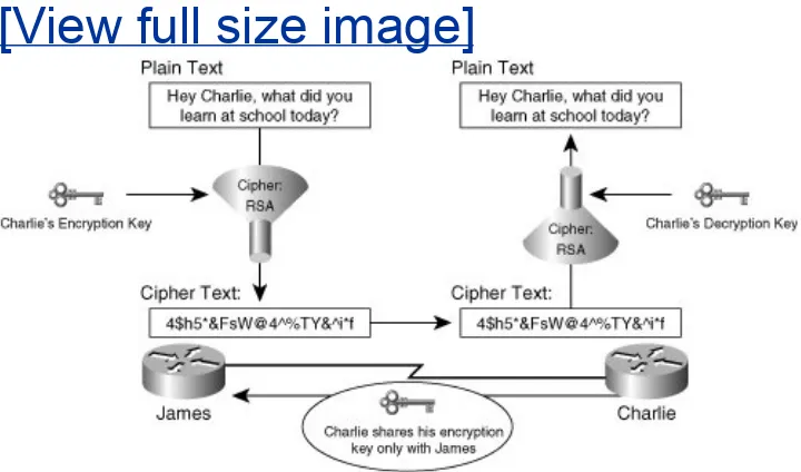
Incorporating the appropriate data confidentiality capabilities into a VPN ensures that only the intended sources and
interceptors of the message. Figure 1-1 illustrates a high-level exchange of encrypted message between to endpoints, James and Charlie.
Figure 1-1. Confidentiality and Authenticity in
Encrypted Communications
[View full size image]
Encrypting messages relies on the use of a key to encrypt clear text and to decrypt ciphered messages. In the exchange of messages in Figure 1-1, both James and Charlie require the appropriate keys to encrypt and decrypt communications from each other. Assuming that these keys were exchanged or
derived securely (for example, via a Diffie-Hellman exchange, which is discussed in detail in Chapter 2, "IPsec
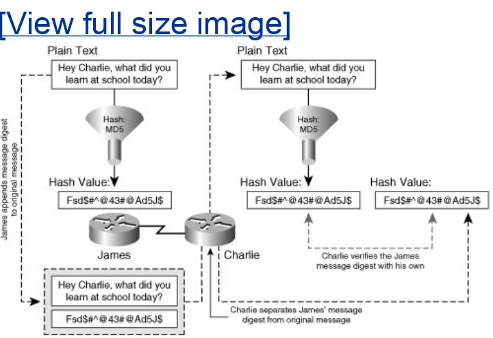
unique messages to the original message before transmission that ensure that the message has not been tampered with in transit. Figure 1-2 illustrates the operation of a hash performed on a message to ensure data integrity.
Figure 1-2. Data Integrity, Secure Hashes
[View full size image]
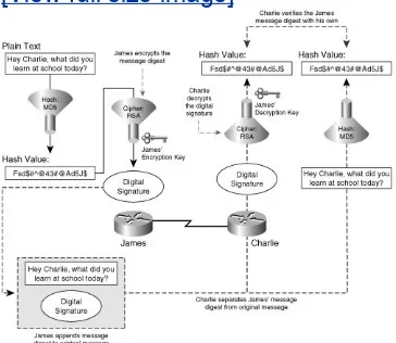
By providing a unique fingerprint specific only to the sender of the message, a digital signature also provides the receiver a method of message authentication and sender non-repudiation. Notice in Figure 1-3 that digital signatures require the use of a public decryption key unique to the sender's private encryption key. The use of this cryptographic keypair thus guarantees
message authenticity, ensuring that the message was sent from the authentic origin, and safeguards against sender
non-repudiation, preventing a situation in which the sender of a specific message intentionally and falsely denies their
data integrity, digital signatures provide added levels of security by offering message authentication and sender non-repudiation, the operation of which is illustrated in Figure 1-3.
Figure 1-3. Message Authenticity and Data
Non-Repudiation with Digital Signatures
VPN Technologies
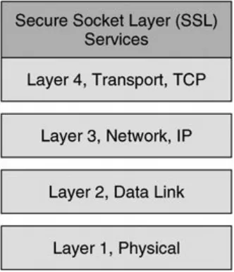
Although IPsec-based VPNs represent one of the most secure and widely deployed types of VPNs, they are only one of many VPN technologies in existence today. As we'll discuss throughout the course of this book, VPNs have been designed to protect data at almost every layer of the OSI stack. For example, customers in different market verticals will deploy a range of encryption technologies, from Layer 1 bulk encryptors to encryption technologies embedded within the applications themselves (SSL-based VPNs).
The OSI model consists of 7 layers, Physical, Data-Link, Network, Transport, Session, Presentation, and Application. Although our primary focus will be IPsec VPNs, which are a Layer 3 VPN technology, it is important to understand IPsec VPNs within the context of other VPN technologies
corresponding to different layers within the OSI stack. Figure 1-4 illustrates the OSI stack and provides some examples of VPN technologies that operate at each corresponding OSI layer
Figure 1-4. VPN Technologies and the OSI Model
Virtual Private Dialup Networks
Virtual private dialup networks (VPDN) are used to tunnel data across a shared media. Although the primary goal of a VPDN is to tunnel data across shared network infrastructures, some VPDNs may also incorporate data confidentiality. Most VPDNs rely on the use of PPP to encapsulate data in transit across a common network infrastructure. Typical VPDN deployments consist of one or many PPP clients establishing a PPP session that terminates on a device at the opposite end of the tunnel, usually located at a central location within the enterprise or service provider edge. In doing so, a secure point-to-point tunnel is established from the client's network to the PPP
concentrator. After the tunnel has been established, the client's network appears as if it were the same network as the
infrastructure across which data is tunneled remains
unchanged. Common VPDN technologies deployed in today's networks include Layer 2 Forwarding Protocol, Point-to-Point Tunneling Protocol, and Layer 2 Tunneling Protocol.
Layer 2 Forwarding Protocol
The Layer 2 Forwarding (L2F) Protocol was originally developed by Cisco Systems as a way to tunnel privately addressed IP, AppleTalk, and Novell Internet Protocol Exchange (IPX) over PPP or Serial Line Internet Protocol (SLIP) dialup connections over shared networks. In order to do this, this VPDN technology concentrates tunnels at a home gateway, allowing all dial-up networks to appear as if their physical point of termination is the home gateway itself, regardless of the location of their
actual dialup termination point. L2F uses control messages on UDP port 1701 to establish the session. Once a tunnel is
established, L2F-encapsulated packets are forwarded in parallel with L2F control datagrams. Both L2F control and payload
datagrams are forwarded on UDP 1701. The L2F encapsulated PPP packets have the format described in Figure 1-5.
Figure 1-5. L2F Data Packet Format
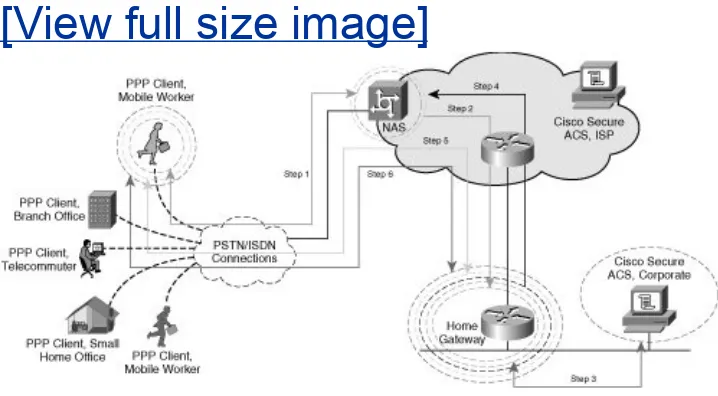
During the creation of an L2F tunnel, initially a user dials into the Network Access Server (NAS), negotiates PPP, and is
Figure 1-6. L2F Topology and Tunnel
Establishment
[View full size image]
Note
In an L2F environment, a "home" gateway refers to a gateway located at the corporate headquarters.
The following steps describe the creation of an L2F tunnel, as illustrated in the steps in Figure 1-6:
1. NAS and the PPP client negotiate a PPP session. NAS
authenticates the PPP client with CHAP (or, optionally, PAP).
Note
the AAA (or in this case, Cisco Secure Access Control
Server) server in the service provider cloud. Managing user connections centrally would ease the administrative burden and provide additional accounting and user database
synchronization capabilities (that is, synchronization with NT databases and automated backup of AAA data on peer
CSACS databases).
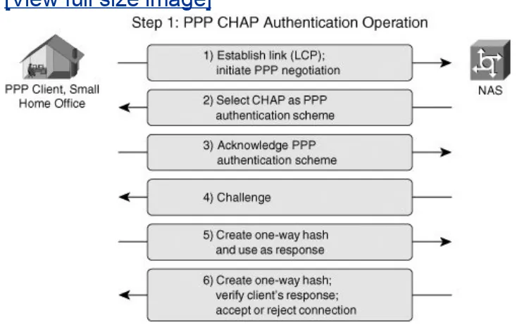
Once the PPP session has been authenticated, a series of exchanges are performed to offload the termination of the dialup session to the home gateway. Figure 1-7 illustrates the CHAP handshake between the PPP client and the NAS shown in Figure 1-6.
Figure 1-7. PPP Authentication with CHAP
[View full size image]
3. The home gateway authenticates NAS against the authentication database (RADIUS or TACACS+).
4. The home gateway confirms acceptance of the tunnel negotiation initiation request from NAS.
5. The home gateway and PPP client negotiate additional
authentication, authorization, accounting, IP addressing, and tunneling parameters.
6. An L2F tunnel is established and maintained between the PPP client and the home gateway.
Note
For more information on L2F, refer to RFC 2341 at
http://www.ietf.org/rfc/rfc2406.txt.
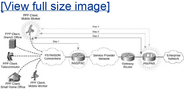
Point-to-Point Tunneling Protocol
Point-to-point Tunneling Protocol (PPTP), a technology originally created by Microsoft, provides a seamless integration of remote PPP capable devices into an enterprise network. PPTP leverages authentication parameters inherent to native PPP and the
tunneling capabilities of GRE to establish a VPDN. After a client has established a PPTP tunnel to a concentrator on a centralized enterprise network resource, that client appears as if it were part of the enterprise network itself, regardless of the
operations executed when a client accesses the VPDN using PPTP.
Figure 1-8. PPTP Topology and Tunnel
Negotiation
[View full size image]
The PPP client in this scenario needs to connect to their
enterprise network. The corporation's security policy mandates that data be separated from the common service provider
infrastructure and that central network connectivity provided by the service provider must remain transparent to the PPP clients, who are PSTN or ISDN attached. In order to accomplish this task, PPTP is used to provide an end-to-end tunnel for PPP connections inbound to the service provider.
following steps (illustrated in Figure 1-8):
1. The first step in the negotiation occurs when the PPP client establishes a connection with the NAS and is authenticated through a chosen form of PPP authenticationPAP, CHAP, or Microsoft CHAP (MS-CHAP). PPTP tunnels can be encrypted through the use of Microsoft Point-to-Point Encryption
(MPPE) to provide confidentiality in VPDNs. Cisco IOS
supports both 40- and 128-bit MPPE encryption. In order to encrypt a PPTP tunnel using MPPE, the network
administrator must use MS-CHAP to authenticate PPP connections to the NAS.
Tip
Authentication of PPP sessions can be passed to a centrally managed authentication database, such as CSACS via
RADIUS or TACACS+. Authenticating PPP sessions against a CSACS database greatly eases administration of user
authentication data for VPN access.
2. Now that the PPP client has accessed the service provider network, the client has IP connectivity to the PNS at its corporate headquarters. The PPP client and the PNS must maintain two connections to one anothera control
connection and a tunnel protocol connection. The PPTP control connection maintains the connection state and negotiates call setup and teardown. As such, it must be established before the tunnel protocol connection can be established. Once an NAS receives the call from the PPP client, the next step in creating the VPDN connection is to either establish a compulsory tunnel from the NAS/PAC to the PNS or to establish a voluntary tunnel from the PPP
scenario, the PIX is acting as the PNS for the PPTP
exchange. The client initiates the tunnel by establishing a TCP connection to the PNS on port 1723.
Caution
In many cases, including the example in Figure 1-8, TCP port 1723 must be allowed through any corporate firewalls or other filtering security devices for PPTP to operate
correctly. In this scenario, the PIX would be configured with the appropriate static translation and access list entry on its outside interface to allow TCP sessions from remote clients on port 1723.
3. Once the PPP client and the PNS have TCP connectivity, they can start to exchange PPTP tunnel negotiation information between them. The tunnel negotiation process consists of exchanging connection request and reply messages as defined in RFC 2673 between the PNS and the PPP client.
Tip
As with PPP authentication on the NAS/PAC, PPTP connections on PIX firewalls and Cisco routers can be authenticated against a Cisco Secure ACS database using RADIUS or TACACS+. Implementing user accounts on a central CSACS database greatly eases administrative overhead.
GRE to tunnel PPP frames over the IP cloud, which, in Figure 1-8, is the service provider network. The GRE-encapsulated format of the PPTP tunneled packet is illustrated in Figure 1-9.
Figure 1-9. PPTP Tunnel Protocol Data Structure
Note
The header used in the PPTP encapsulation process is similar to a GRE header, with some slight modifications to the
specification outlined in RFC 1701. The PPTP version of the GRE header includes an acknowledgment field to determine the rate at which packets are traversing the PPTP tunnel.
The preceding scenario describes a voluntary PPTP tunnel negotiation between the PPP client, which also acts as its own PAC, and the corporate PIX Firewall, acting as the PNS. In a compulsory PPTP tunnel negotiation, the NAS would act as the PAC and would multiplex multiple sessions from the PPTP clients into a single tunnel to the PIX, or PNS. The exchanges in a
compulsory tunnel would follow the same steps chronologically, but would appear as displayed in Figure 1-10.
[View full size image]
Note
Although both L2TP and PPTP support both voluntary and compulsory tunnels, Cisco IOS only supports voluntary and compulsory tunnels for L2TP. While voluntary PPTP tunnels are supported in Cisco IOS, compulsory PPTP tunnels are currently not supported.
As depicted in Figure 1-10, only a single tunnel is negotiated between the PAC/PNS pair. In a voluntary exchange, it is possible that all 5 PPP clients dialing into the NAS terminate separate tunnels with the PIX/PNS. As such, compulsory tunnel architectures can be used to keep tunnel termination overhead low on the PNS. In the examples in this chapter, the voluntary tunnel negotiation option could yield up to five times the tunnel maintenance of a compulsory tunnel negotiation option (five PPP clients initiating tunnels to the PIX in a voluntary
arrangement vs. one tunnel initiated from the NAS in a compulsory setting).
confidentiality with MPPE. In the preceding compulsory
arrangement, the PPP connections to the NAS would remain unencryptedonly the connection from the PAC to the PNS would be encrypted with MPPE. As such, those network administrators requiring fully confidential exchange of data in their PPTP
environments should choose to allow their clients to voluntarily negotiate an end-to-end PPTP tunnel with the PNS or, in this case, the corporate PIX Firewall. In doing so, the network administrator can ensure that all legs of the VPDN from their remote dialup hosts using PPP to their corporate PNS are encrypted for end-to-end data confidentiality.
Layer 2 Tunneling Protocol
Layer 2 Tunneling Protocol (L2TP) is a collaborative effort to develop a standards-based VPDN protocol within IETF. Vendors collaborating on this initiative include, among others, Cisco and Microsoft. As with PPTP, L2TP is a client-server operation
consisting of two main components:
L2TP Access Concentrator (LAC) The LAC represents the client side of this network and typically exists on the switch infrastructure between remote dialup nodes and the access server that terminates the inbound PPP sessions across the switched ISDN or PSTN infrastructure. As remote hosts initiate and terminate PPP connections on the NAS, the LAC serves as a proxy originator of L2TP control and tunnel data to the LNS at the corporate network. LACs are often
collocated with the access server itself. A Cisco router or access server is capable of providing LAC functionality within a VPDN.
LAC. As users connect to the LAC, connections are
multiplexed across the negotiated tunnel to the LNS, where they are eventually terminated.
A typical L2TP session resembles a compulsory PPTP tunnel negotiation between a PAC and a PNS. As with PPTP, two types of data are forwarded into an L2TP tunnelcontrol data and
tunnel data. Unlike PPTP, however, L2TP is not connection
oriented. Instead, it is packet oriented. So, whereas PPTP relied on a TCP-based connection to establish a control channel
between the PAC and PNS, L2TP uses UDP to maintain control data and tunnel data simultaneously. L2TP leverages the use of control messages and data packets as follows:
L2TP control messages negotiate tunnel setup and
maintenance. Control messages establish tunnel IDs for new connections within an existing tunnel. They also tear down and remove previously established tunnel IDs within an existing L2TP tunnel. L2TP control messages are
originated on a given source port and forwarded to UDP destination port 1701.
L2TP payload packets tunnel data within a given network. When data is tunneled from LAC to LNS across an IP cloud, it is encapsulated with an L2TP header. The format of the L2TP payload is illustrated in Figure 1-11. As with L2TP control messages, L2TP payload packets are forwarded to UDP 1701.
Figure 1-11. L2TP Tunnel Protocol Data
Structure
Note
L2F control and payload packets are also sent on UDP port 1701. Network devices inspect the version field to differentiate between L2F and L2TP packet formats.
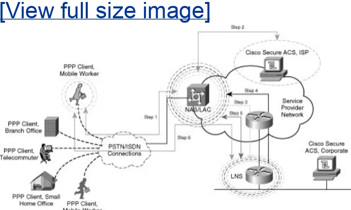
Figure 1-12 depicts a sample L2TP tunnel setup in which a company uses L2TP to establish seamless, secure connectivity across an untrusted media. In this case, that shared network is the ISP cloud. The ISP owns the access server that terminates the customer's dialup connection using PPP as the Layer 2 protocol. In this example, the access server also serves as the LAC. The LNS is located on the customer premises and
terminates the L2TP tunnel originated from the LAC.
Figure 1-12. L2TP Tunnel Negotiation
The following steps outline the creation of the L2TP VPDN from the remote host to the corporate network as described in Figure 1-12:
1. The user dials in to the NAS/LAC over PSTN or ISDN. The user establishes a PPP connection with the NAS and is authenticated with CHAP.
2. The user initiates an L2TP tunnel and is prompted for a
username and password. The ISP inspects the remote user's username and authenticates it against its central
authentication database via TACACS+ or RADIUS.
3. Once authenticated, the LAC initiates an L2TP tunnel to the LNS located at their corporate facility.
4. The LNS receives the request for tunnel negotiation and optionally authenticates the request against the corporate central authentication database via TACACS+ or RADIUS. The LNS responds with either an acceptance or a rejection of the tunnel initiation to the LAC.
5. The LNS creates a virtual interface for the tunnel ID corresponding to the requesting remote PPP client. The remote PPP client and the LNS are now able to exchange authentication, authorization, accounting, and IP addressing data with one another over the tunneled PPP session. L2TP headers are stripped on ingress at the LNS for inbound
connections from the PPP client. Likewise, L2TP headers are stripped at the LAC for outbound connections from the LNS to the PPP client.
6. A PPP connection now exists between the PPP client and the LNS. Additionally, an L2TP tunnel has been negotiated
authenticated at the ISP, the LAC does not create a new
L2TP tunnel but instead adds a new tunnel ID to the existing tunnel for that client.
Multiprotocol Label Switching VPNs
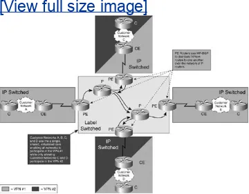
Multiprotocol Label Switching (MPLS) VPNs logically separate VPN traffic over a shared media through the use of VPN Routing and Forwarding Instances (VRFs). In an MPLS network, different devices play different roles to achieve this logical separation:
Provider (P) Router: P routers typically comprise the MPLS core and therefore provide transport between PE routers. Instead of using IP routing information base (RIB) or IP forwarding information base (FIB) lookups to make forwarding decisions, P routers use a label forwarding information base (LFIB) lookup to make their forwarding decisions. Convergence of the LFIB between P routers in the provider network is facilitated through the use of Label
Distribution Protocol (LDP).
Provider Edge (PE) Routers: PE routers typically provide the interface between the service provider and the
customer, and it is most common for the provider to own the PE router. PE routers communicate information about VPNv4 addresses, including the IPv4 prefix and 8-byte route descriptor, between one another using the Multiprotocol
Border Gateway Protocol (MP-BGP), enabling convergence at the PE.
Note
VPNs, please refer to the following IETF RFC:
http://www.ietf.org/rfc/rfc2547.txt
Customer Edge (CE) Routers: CE routers provide the interface to the PE routers. CE routers typically perform forwarding decisions based on standard RIB or FIB lookups, and convergence between CE routers and the PE router can typically be achieved through the use a standard IGP.
Caution
An MPLS VPN does not provide confidentiality unless it is deployed in conjunction with IPsec.
A VRF describes a separate routing and forwarding table, enabled by the use of Route Descriptors, which are 8-byte unique identifiers derived from VPN-specific information at the provider edge (PE). MPLS VPNs enable customer edge (CE) routers to establish normal Layer 3 RP adjacencies with MPLS-aware PE routers. Each PE router is MPLS VPN MPLS-aware and is able to forward traffic to its destination PE router on the opposite side of the provider core using VPNv4 addresses learned from MP-BGP advertisements from other PE routers. The provider core routers remain unaware of the customer network's routing table or IP addressing information. Instead, traffic is switched within the MPLS cloud using labels and an entry in the P
router's label forwarding information base (LFIB). Figure 1-13
Figure 1-13. Traffic is IP-Routed to the Provider
Edge (PE)
[View full size image]
When the traffic from the customer edge reaches the PE router, it is then label switched across the MPLS Service Provider core to its destination PE router. In this manner, customer routing and IP addressing information is kept virtual and private from the provider corethe P routers use MPLS labels and an
associated LFIB entry to forward the traffic across the MPLS core rather than IP addressing information.
When MPLS-switched traffic arrives at the destination PE router, traffic can be forwarded to neighboring CE routers based on the previously installed VPNv4 address learned from MP-BGP
appropriate destination and forwarding decisions within the customer core IP network.
The operation of MPLS offers separation of multiple virtual data networks across a shared network such as an ISP. The addition of MPLS labels at the service provider core allows customers to separate networks from other customers virtually over a shared core network such as a service provider network. The use of route descriptors on PE nodes provides separation at the control plane, allowing customers to use overlapping address space and overlapping services that would normally present conflict within a non-MPLS environment. As mentioned previously, data-plane separation is achieved using VPN labels to make the forwarding decisions on PE routers.
IPsec VPNs
IPsec VPNs encrypt data at the Layer 3 IP packet layer, offering a comprehensively secure VPN solution through providing data authentication, anti-replay protection, data confidentiality, and data integrity protection. As such, IPsec is one of the most widespread VPN technologies in today's enterprise, service
provider, and government networks. Using ESP in tunnel mode, IPsec supports the rewrite of Type of Service (ToS) bits into an outer IP header, thereby supporting encrypted data payloads while preserving quality of service (QoS) within a given
network. IPsec is a standards-based protocol and therefore
supports interoperability across products from multiple vendors.
Note
Although IPsec is standards based, there are many optional components of IPsec (not required for RFC compliance) and proprietary innovations that present compatibility
"Handling Vendor Interoperability with High Availability."
As we will discuss, IPsec is supported within Cisco IOS on a wide array of different routers, firewalls, VPN Service Modules, VPN concentrators, and VPN clients. Likewise, Cisco offers a variety of different hardware-based VPN acceleration options for enhanced VPN performance within a network. IPsec will serve as the primary VPN discussion point for the duration of this book.
IPsec VPNs tunnel data across shared media using ESP, AH, or a combination of both. These two standards-based protocols both use symmetric encryption technology.
Note
The precise operation of ESP and AH are outlined more comprehensively in Chapter 2.
IPsec-supported symmetric encryption transforms include data encryption standard (DES, 56-bit transform), triple data
Transport Layer VPNs
Transport layer VPNs provide an additional layer of security at the transport of the OSI stack. Transport layer VPNs typically consist of a client application and a server. A transport layer VPN will undergo a handshake to agree on common parameters to use for the SSL or TLS session, including cryptographic
keying material and transforms. The messages in this
handshake are confidentially exchanged between client and server, typically with a form of public key encryption such as RSA encryption. During the handshake, the client and server also agree on a set of symmetric session keys and a symmetric key transform, such as DES or 3DES, for bulk data encryption over the SSL VPN.
Secure Socket Layer VPNs
In today's network architectures, Secure Socket Layer (SSL)
VPNs represent one of the most popular choices for transport layer security. SSL was originally developed by Netscape in 1994 to secure client/server applications across the Internet. SSL is effective at providing data authentication, data integrity, and data confidentiality between client and server applications, but it does not offer data non-repudiation services. As discussed before, SSL is performed over TCP in the transport layer of the OSI stack, as illustrated in Figure 1-14.
SSL follows five broad steps when establishing a secure sessionclient exchange of cryptographic parameters, server exchange of cryptographic parameters, cryptographic key derivation, session authentication, and secure data exchange. Refer to the scenario illustrated in Figure 1-15 for the following description of SSL tunnel negotiation. In the SSL tunnel
negotiation, public key encryption is typically used for initial client and server authentication. The client and server also exchange public keys to encrypt each message in the
handshake. Once the handshake is completed, symmetric key transforms are used for bulk data encryption between client and server.
Figure 1-15. SSL Tunnel Establishment
The following order of operations describes the SSL handshake illustrated in Figure 1-15:
Note
RSA signatures are commonly used to facilitate the
authentication and confidential exchange of messages during the SSL handshake. RSA Signatures, including x.509-based
IPsec."
1. Client Exchange of Cryptographic ParametersThe client and server must agree on the parameters used for
encryption, such as the encryption algorithm, key exchange method, and hash method to use for data integrity. If the client and server have not already agreed on these
parameters, then the client will initiate the exchange of messages to negotiate mutually acceptable parameters to use for future operations using by sending a CLIENT-HELLO message to the concentrator.
2. Server Exchange of Cryptographic ParametersThe server responds to the CLIENT-HELLO message with a SERVER-HELLO message and, optionally, several other messages:
SERVER-CERTIFICATE Contains the servers's public key for server authentication and pre-master secret encryption.
SERVER-KEY-EXCHANGE Optionally used to encrypt the CLIENT-KEY-EXCHANGE message in Step 3 below.
CLIENT-CERTIFICATE-REQUEST The SSL
concentrator or server can optionally request a client certificate for authentication. If this message is sent to the client, the client's server must be forwarded to the SSL concentrator and successfully validated.
strongest supported symmetric key cipher specified in the CLIENT-HELLO message from Step 1. At this point, the client and server should have the appropriate information
necessary to agree on cryptographic parameters. A SERVER-HELLO-DONE message is then forwarded to the SSL client to indicate that the SSL server has received the required
information for this sequence of the handshake and is awaiting information from the client (as described in the next step).
3. Cryptographic Key DerivationThe client is now ready to generate and share its pre-master secret key with the SSL server. The pre-master secret is comprised of a 48-byte value (in the case where RSA is used). This value is then encrypted with the SSL server's public key and forwarded to the SSL server using a CLIENT-KEY-EXCHANGE message. Optionally, the client will also forward two additional
messages at this point in the SSL handshake:
CLIENT-CERTIFICATE The client must possess a certificate and forward it to the server using this
message if the client receives a CLIENT-CERTIFICATE-REQUEST in Step 2 above.
CERTIFICATE-VERIFY This message is a hash of all previous handshake messages appended. It is sent to the SSL server to validate the authenticity and data integrity of the CLIENT-CERTIFICATE message (and all other previous handshake messages) if the client
receives a CLIENT-CERTIFICATE-REQUEST in Step 2 above.
The SSL Server decrypts the CLIENT-KEY-EXCHANGE
hashing the pre-master secret with the ClientRandom and ServerRandom values shared in Step 1. The master key is then used to derive 4 session keys that SSL will use to encrypt data:
Client Write MAC Secret Client uses this key to create a hash appended to the original message; server uses this key to verify the hash.
Server Write MAC Secret Server uses this key to create a hash appended to the original message; client uses this key to verify the hash.
Client Write Key Client uses this key to encrypt messages; server uses it to decrypt messages.
Server Write Key Server uses this key to encrypt messages; client uses it to decrypt message.
The client concludes this phase of the SSL handshake by sending a CLIENT-FINISHED message to the server. The FINISHED message contains a hashed value of all previous messages in the handshake to this point. The server verifies this message to determine that the previous exchanges
have indeed been authentic with preserved data integrity.
4. Session AuthenticationThe SSL concentrator or server must validate the hash (MAC) sent in the client FINISHED message received in Step 3 above. Upon successful
handshake to this point. Upon receipt of this message, the SSL client performs a validation of the MAC received in the server FINISHED message so that it too can assume that the handshake has completed with authenticity and preserved data integrity.
5. Confidential Exchange of Data with Preserved
IntegrityThe client and server now use the session keys derived from the master secret in Step 1 to encrypt and decrypt data sent to and from one another. This is done through an agreed-upon cipher transform such as DES or, in this case, 3DES. However, to ensure data integrity, a hashed message authentication code (HMAC) is appended to the original message. The newly formed payload (original
message + HMAC) is encrypted with the selected transform.
Note
The creation of hashed message authentication codes is covered in greater detail in Chapter 2.
Transport Layer Security and SSL VPNs
SSL was originally developed by Netscape and has proven to be effective for HTTPS communications. However, the IETF
TLS has big implications in 802.1x identity-based networking systems, because extensible authentication protocol with TLS (EAP-TLS) is part of the 802.1x standard. Additionally, TLS is a critical component in wireless network security. Although not formally a component of the newly ratified 802.11i IEEE
Common VPN Deployments
Network infrastructures in which a VPN technology may be commonly deployed include, but are not limited to, trunks to Internet service provider networks, corporate extranet partner networks, or even private leased line connections in a corporate intranet. Next, we will briefly explore some of the common
situations in which a VPN may be deployed.
Site-to-Site VPNs
As cryptographic technology becomes more embedded in various network elements, growth in site-to-site VPN
deployments has risen. A site-to-site VPN could be as simple as encrypting the link between two different nodes on a point-to-point connection. Or it could be slightly more complex,
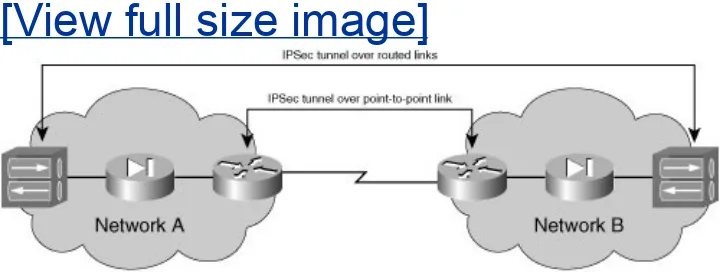
offloading the initiation and termination of the VPN tunnel to a firewall or VPN concentrator on each organization's DMZ. Figure 1-16 illustrates a simple site-to-site IPsec VPN deployment
between two networks, A and B.
Figure 1-16. Simple Site-to-Site Design Scenario
Although the two IPsec tunnel implementations in Figure 1-16
use the same physical topology to accomplish a similar task, there is a significant difference between these two simple site-to-site VPN designs. For example, if a smaller router is used for the WAN connection, there could be a substantial improvement in VPN performance by processing IPsec on the VPN
concentrators. In such a case, the routed IPsec tunnel between the two VPN concentrators would be an optimal choice.
However, if the PIX are performing network address translation (NAT), the VPN concentrators may need support for special
features, such as IPsec NAT Transversal (IPsec NAT-T), for IPsec to work properly. If the concentrators do not have the
appropriate features, the IPsec tunnel built over the point-to-point line might be a better option.
In the scenario in Figure 1-16, it is critically important to note that the flexibility to choose between the two tunnel
deployments is enabled by the fact that IPsec VPNs operate at Layer 3, the network layer, of the OSI model. As such, VPNs are no longer limited to bulk data-link encryption techniques on physical point-to-point links. Instead, an IPsec VPN tunnel could be used to secure traffic between two endpoints over a series of routed networks. The simple design decision presented in Figure 1-16 is just an introduction to the wide array of design options that should be considered when securing a network with a Layer 3 VPN technology such as IPsec.
Site-to-Site VPN connections are not only used to secure
connectivity between two different organizations, but they are also used to secure links within an organization itself. As
network topology in enterprise network WANsa hub-and-spoke topology. In this scenario, the 7200 terminates multiple point-to-point connections from a combination of branch routers.
Figure 1-17. Hub-and-Spoke Networks and
Site-to-Site VPNs.
[View full size image]
Tip
Hardware-based crypto-accelerators allow head-end devices to scale the number of IPsec tunnels in a hub-and-spoke network dramatically. Cisco currently offers many choices for VPN
hardware-based acceleration in routers and switches designed for the data center and branch office.
In a hub-and-spoke topology, a dynamic multipoint VPN
(DMVPN) configuration can help scale the number of security associations supported. DMVPNs use next hop routing protocol (NHRP) and multipoint GRE (mGRE) tunnels to establish direct security associations between the branches, as opposed to one security association (SA) from branch to head-end and another from head-end to the destination branch. Chapter 8 covers DMVPN in greater detail.
Site-to-site VPN deployments are also popular in corporate extranets. When an organization requires dedicated site-to-site connectivity to a peer organization or subsidiary, often, a
dedicated, high-speed WAN circuit is provisioned, not unlike the way Enterprise Network A is connected to Enterprise Network B in Figures 1-16 and 1-17. When an organization requires
multiple dedicated external connections to other peer
organizations, extranets are formed. Figure 1-18 illustrates an extension of the VPN topologies illustrated in Figure 1-16 and 1-17 to include a extranet deployment comprised of multiple site-to-site IPsec VPN tunnels.
Figure 1-18. Corporate Extranet and Site-to-Site
VPNs
Remote Access VPNs
Remote access VPNs (RAVPN) drive workforce mobility and
productivity by allowing secure connectivity from any point that can establish a Layer 3 connection (or in the case of a VPDN, a Layer 2 connection) to the network. As home high-speed
RAVPN infrastructures consist of two main componentsthe VPN client and the VPN concentrator:
VPN clients can either be hardware based or software based. Cisco offers the 827 VPN router or the 3002
hardware-based VPN client for RAVPN solutions. Software-based VPN clients run on the remote or mobile user's
desktop or laptop PC. Cisco offers VPN client software for RAVPN software-based client implementations.
VPN concentrators are used to terminate RAVPN connections inbound from VPN clients. Cisco VPN
concentrators offer a scalable solution for terminating large amounts of IPsec connections from VPN clients in an RAVPN solution. VPN concentrators are also capable of providing LNS/PNS functionality for VPDN implementations.
Figure 1-19 illustrates a basic example of a corporate VPN architecture that supports IPsec RAVPN, VPDN, and Extranet VPN access to enterprise networking resources.
Figure 1-19. RAVPN Implementation
SSL in RAVPN Architectures
Traditionally, SSL VPNs were embedded in web browsers for securing transactions in client/server architectures. However, as SSL can be deployed in specific applications, it enables RAVPN capabilities on a per-application basis. As such, SSL RAVPN
solutions offer greater granularity over pure Layer 2 or 3 RAVPN solutions. For example, security administrators for Enterprise Network A may want to allow secure access only to e-mail or only for a specific application on a given web server, as opposed to allowing all of the remote user's IP traffic through the
network. To achieve this, the remote user would use SSL client software installed with their web browser. The security
Business Drivers for VPNs
As the amount of data that traverses untrusted, shared infrastructures continues to increase, so does the need for secure transmission of that data. Now that you've seen some introductory concepts related to site-to-site VPNs, here are some examples of real-world business applications for site-to-site VPN deployments.
Global financial services organizations transfer billions of dollars worth of information across data links every day. Consider the common scenario of an institutional investor making a
substantial equity trade based on real-time market data. The receiver of that instruction must be assured that the originator of the trade is authentic, or else millions of dollars could be lost by executing the transaction. Multiply the number of these
types of transactions by thousands, and the economics of a VPN investment become apparentthe losses resulting from a single attack on such an institution could justify the investment
required for the entire VPN deployment.
Large international retailers process thousands of orders daily from huge numbers of customers. In order to expand their customer reach, retailers are relying on online ordering
systems, dependant on the Internet as a critical distribution channel. In each transaction, sensitive customer data is sent over untrusted mediathe service provider core. Retailers have responded by investing in transport-layer security mechanisms such as SSL to provide authentic, confidential exchange of data with ensured integrity. Providing VPN capabilities for additional security over connectivity to the retailer guarantees the private exchange of customer data, which is critical to consumer
adoption of online ordering systems.