DESIGN DEVELOPMENT OF FIXTURE MODEL
IN MANUFACTURING SPRING SHACKLE
Didi Widya Utama1, Jemmy Septiawan2, Edward Suhartono2, Roby2
1)Lecture Department of Mechanical Engineering, Tarumanagara University 2)Student Department of Mechanical Engineering, Tarumanagara University
e-mail: [email protected], [email protected], [email protected], [email protected]
Abstrak: Spring shackle merupakan komponen penting dalam sistem suspensi pegas daun karena memungkinkan pegas tersebut meregang ketika kendaraan mengalami lonjakan atau sedang mengangkut beban berat. Desain fixture-komponen yang berfungsi untuk mencengkeram benda kerja selama proses manufaktur berlangsung-menentukan efisiensi proses manufaktur spring shackle. Dalam penelitian ini, akan dibahas pengembangan desain fixture spring shackle dengan metode Design for Manufacture and Assembly (DFMA). Pemodelan fixture secara 3D dengan menggunakan CAD terbukti membantu dalam memvisualisasikan dan mengkomunikasikan pengembangan desain fixture spring shackle tersebut. Hasil yang diperoleh dari pengembangan desain fixture terjadi penghematan waktu sebesar sebesar 82,22% ditinjau dari aspek Design for Assembly (DFA) dan 19,25 % ditinjau dari aspek Design for Machining (DFM).
Kata kunci: fixture, DFMA, CAD, manufaktur
Introduction
Spring shackle is an important component in leaf spring suspension system, mostly used for heavy duty vehicles, such buses and trucks. Manufacturing process of spring shackle is divided into two processes, which are casting (primary) and machining (secondary).
In the machining process, fixture has an important role to hold the workpiece. Fixture design determines the efficiency of spring shackle’s manufacture because it affects the time of manufacture, which are loading and unloading time.
A fixture design, developed by Mechanical Engineering Department Universitas Tarumanagara, is based on a design which has been planned to be manufactured by PT X.
Research Aim
To develop a fixture design of spring shackle, using Design for Manufacture and Assembly (DFMA) methodology, so it can be obtained a new design which is able to save manufacturing time.
Methodology
Firstly, PT X’s fixture design is analyzed. From the analysis, weaknesses of this design are identified. And then, the weaknesses, such as the number of fixtures and bolts, fixture position, separated operation, and tool acquire time, are overcome by developing the fixture design [1].
Developed fixture design replaces some features to overcome the weaknesses. It uses clamping system, snap fit system, and also some modifications, such as the ease of alignment and geometry of cutting tool. This developed fixture design then is also analyzed with the same method as the PT X’s one.
After both former and latter analysis are fulfilled, the time for assembling and manufacturing spring shackle, using the developed fixture design, is compared to the time,
using the PT X’s one. If the time consumed is shorter than the PT X’s one, it means the developed fixture design is available to use then the design detail is received, followed by conclusions of the development has been made.
Discussion and Result
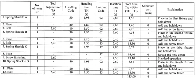
Based on DFA analysis, the result of total assembly time for fixture PT X is illustrated in Table 1.
Table 1. DFA Analysis for Fixture PT X
Based on DFM analysis, the result of total machining time for fixture PT X is illustrated in Table 2.
Table 2. DFM Analysis for Fixture PT X [2]
No. Process Time (s)
1 Boring 70,8 2 Boring 39 3 Face mill 33 4 Milling 18,6 5 Milling 18,6 6 Face mill 33 7 Drilling 3,36 8 Face mill 27 9 Slitting 27,6 10 Face mill 27 Total 297,96
The development embraces an integrated machining process, saving the machining time, and a cam system used for clamping mechanism [3]. The type of cam is direct clamping, using walking cam and indirect clamping, using finger driven by cylindrical cam [4].
Figure 2. Walking Cam Mechanism
Walking cam has three surface contacts as shown in Figure 2. A side beneath the upper one of cam clamps spring shackle along Z axis, lower side of cam clamps spring shackle along X axis, and the finger clamps spring shackle along Y axis. The setting of bolt upon the cam affects the strength of clamping.
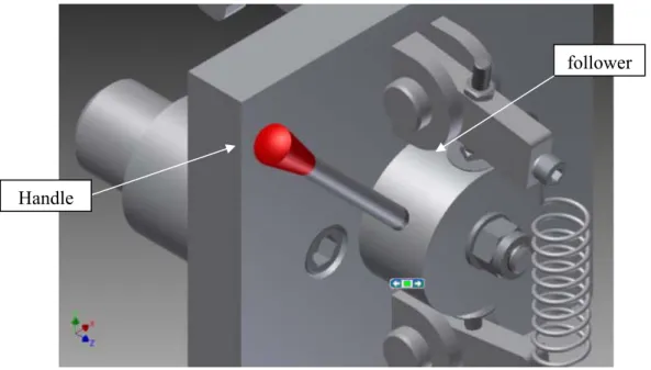
Cylindrical cam utilizes its unique elliptical-shaped profil to generate a force on follower when the handle revolves. Thus, the follower will drive a clamping mechanism. A spring is used to reposition the follower to initial position after clamping.
Figure 3. Cylindrical Cam Mechanism
Based on the same DFA analysis as the former one, the result of total assembly
Finger Handle Cam follower Handle
Table 3. DFA Analysis for Fixture After Development
Based on the same DFM analysis as the former one, the result of total machining time for fixture after development is illustrated in Table 4.
Table 4. DFM Analysis for Fixture After Development [2]
No. Process Time (s)
1 Boring 70,8 2 Boring 39 3 Face mill 33 4 Face mill 15,6 5 Drilling 3,36 6 Face mill 27 7 Slitting 27,6 8 Face mill 27 Total 243,36
There is a significance difference in total time consumed for assembly and machining at both developed and PT X’s fixture which can be seen in Table 5.
Table 5. Comparison of Both Fixture Designs’ Results No. Design Total Time DFA (s) Total Time DFM (s)
1. PT X’s fixture 113.00 297.96
2. Developed fixture 19.05 243.36
Acknowledgement
Thanks to Mechanical Engineering Department Universitas Tarumanagara which has donated and supported the research until its accomplishment. There’s still a probability to do a further research to obtain more satisfying results of it, such as analyzing the strength and capability of the fixture to overcome the load, applied during the assembly and machining. This research has won the fifth place in “Lomba Nasional Tahunan Rancang Bangun Mesin 2011”, held by Badan Kerja Sama Teknik Mesin–Indonesia on November, 2nd 2011.
Conclusion
The application of cam method in clamping system accelerates and simplifies the process of clamping itself so it reduces a cycle analytic time, whereas the cycle analytic one for a spring shackle, using PT X’s fixture is 410.96 s and using developed fixture is 262.41 s. The analytical result indicates that cycle anlaytic time for developed fixture is shorter, compared to the PT X’s fixture, which are 93.95 s or 83.14% from DFA aspect and 54.60 s or 19.25% from DFM aspect. The result can be achieved due to fixtures’ adjacent layout in the developed fixture, shortening the uncut tool path, as well as the identification and elimination of obstructed access and restriction vision by using 3D model CAD [5].
References
1. Boothroyd, Geoffrey, Peter Dewhurst, and Winston Knight. Product Design for Manufacture and Assembly. New York: Marcel Dekker, Inc., 2002.
2. Complete Machining Solutions The Concise Catalog of Metal Working Tools. Israel: ISCAR LTD., 2004.
3. Grant, Hiram E. Jigs and Fixtures Non-standard Clamping Devices. New Delhi: Mc Graw-Hill, 1978.
4. Hoffman, Edward G. Jig and Fixture Design. Fifth Edition. USA: Thompson Delmar Learning, 2004.
5. Krumenauer, F. Z. “Concurrent Engineering and DFMA Approaches on the development of Automotive Panels and Doors”. In Journal of Achievements in Materials and Manufacturing Engineering (Volume 31 Issue 2, Desember 2008).
![Table 4. DFM Analysis for Fixture After Development [2]](https://thumb-ap.123doks.com/thumbv2/123dok/2136782.2704930/5.892.262.652.514.748/table-dfm-analysis-fixture-development.webp)
