DOI: 10.12928/TELKOMNIKA.v14i3.3748 963
H-INFINITY Control for Pitch-Roll AR.DRONE
Agung Prayitno*1, Veronica Indrawati2, Clark Arron3 Electrical Engineering Department, University of Surabaya (UBAYA), Jl. Raya Kalirungkut – Surabaya 60293, East Java – Indonesia, Tel.+62-31-2981157 *Corresponding author, e-mail: [email protected], [email protected],
Abstract
This paper describes the design and implementation of H-infinity controller applied to the AR.Drone to follow a given trajectory. The trajectory will be achieved by using two control signals, pitch and roll. Pitch and roll of the AR.Drone models are obtained by assuming that the transfer function of internal control for pitch and roll is the second order system. Two schemes of H-infinity controller designed for pitch and roll. H-infinity control for x-position has exogenous input of the x-reference, xref, control input of pitch value, exogenous output in the form of x-position and process output as error x. While H-infinity control for y-position has exogenous input of y-reference, yref, control input in the form of roll value, exogenous output of y-position and process output as error y. The results of simulation and implementation show that drone can follow multiple references of trajectories given.
Keywords: AR.Drone control, H-infinity controller, pitch control, roll control
Copyright © 2016 Universitas Ahmad Dahlan. All rights reserved.
1. Introduction
Various applications of Unmanned Aerial Vehicle (UAV) have been widely used today for news reporting, disaster missions, expeditions, videography for tourism, businesses and others. UAVs are mostly still controlled by humans from the ground station. The existence of autonomous flight feature will be very helpful when terrain and environment restrict human movement. This paper presents the development of an automated algorithm scheme on one type of UAV, the AR.Drone quadrotor.
AR.Drone has become one of the research platforms that are widely used by researchers, especially for those who focus on the development of algorithms. Algorithm development with AR.Drone platform is faster because AR.Drone is equipped with several sensors: 3 axis gyroscope, 3 axis accelerometer, a sonar altimeter, and the front and bottom cameras. AR.Drone is also equipped with an onboard computer that can be used for basic controls, such as: vertical take off landing, hovering, forward-reverse, right and left maneuvering by giving a value between -1 to 1 on the pitch, roll, yawrate, and vertical rate input. Providing a positive pitch value (+) means ordering the drone to fly backward while a negative pitch value (-) means ordering the drone to fly forward. Positive roll value (+) means ordering the drone to fly right sideward, and left sideward for negative roll value (-). To pivot clockwise motion, positive yawrate value must be given to the drone and negative (-) for the opposite motion. Positive (+) vertical rate value is given to the drone to maneuver vertically upward and negative (-) for reverse maneuver. Range values -1 and 1 are propotional to the minimum and maximum range of the actual value of each input that is set on the configuration of its innerboard. Through Wi-fi communication, control command can be sent from a PC in the ground system to the innerboard of the AR.Drone and vice versa innerboard can send navigation data to the PC. Navigation data that can be taken include actual roll value, sideward speed, actual pitch value, forward speed, actual yaw rate value, yaw value, vertical rate value and altitude value.
generally consists of the main VI to handle basic control vertical take off landing and fly forward-reverse, right and left maneuver. NavData VI transmits navigation data to PC. Video VI transmits streaming video from two cameras to drone as well as some supporting VI. Many control schemes have been developed by researchers. Emad Abbasi, et al., [4] simulated two control schemes, PID controller and fuzzyPID, to control the height of the quadrotor in turbulence situation. Santos, et al., [5] proposed fuzzy logic to control each of the four rotors using the height, roll, pitch and yaw value as inputs. Sarah Yifang [6] applied some control algorithm such as PID controller, waypoint navigation, trajectory tracking and vision-based controller for a variety of flight formation. Rabah Abbas, et al., [7] implemented the leader-follower scheme using PID controller and directed Lyapunov controller at formation tracking quadrotor. Agung, et.al., [8] implemented the algorithm fuzzy logic controller on the AR.Drone by controlling the value of pitch and yawrate. This algorithm is successfully applied to the AR.Drone to the case of multiple trajectories tracking in the x-y given. Veronica, et al., [9] successfully implemented fuzzy logic controller on drones for waypoint navigation in the field of x-y-z. Some fuzzy logic control schemes were tested in this research using a control signal pitch, roll, and vertical rate. Veronica also compared this method with control scheme used by Agung [10].
Problems experienced by [8-10] is when the drone improve the position x with a pitch resulted in a worsening of the position y, and vice versa. In this paper, H-infinity control scheme will be implemented on the AR.drone to follow a predetermined reference in the field of x-y. By using this scheme is expected to obtain the best compromise between x and y position of the drone. The main contribution of this paper is to show that the H-infinity control scheme can be used to control the position of the AR.Drone quadrotor.
Study literature of H-infinity control scheme is obtained from some researchers. Kruczek, et al., [11] implemented the H-infinity control to the active suspension using linear electric motor. The result showed better results than the passive suspension. Guilherme et.al combined predictive integral methodology to handle the reference trajectory and nonlinear Hinfinity control to stabilize the rotational movement of quadrotor. They also use a nonlinear H-infinity control scheme on quadrotor helicopter that has been modified in order to obtain coupling between longitudinal and lateral movement with the roll and pitch motions to follow a given reference path [12, 13]. Keita Mori, et al., [14] using standard H-Infinity control to reduce disturbance sensitivity of the quad-rotor helicopter.They control both the position and the altitude of the quadrotor model using a new input-output linearization method. Taesam Kang, et al., [15] designed a robust H-Infinity attitude controller of linear models quadrotor obtained from the estimated input – output data using Prediction Error Minimation.
Methodology of writing this paper has been preceded by a summary of the authors on the various researchs that have been done in the field of the AR.Drone. Next will be explained a research method that is divided into four sections which include: (1) the augmented plant that explains the H-infinity scheme to be applied; (2) pitch model that explain how to get the pitch model; (3) roll model that describes roll model of drone; (4) K value that is calculated and simulation that explains how to design a controller. At the end of this paper will be presented the result of implementation in a graph then will be analyzed and summarized.
2. Research Method 2.1. The Augmented Plant
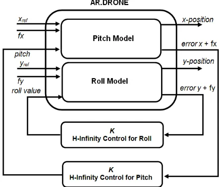
To design the H-infinity controller, the AR.Drone control block must be converted into augmented plant. The augmented plant uses two H-infinity control schemes to control x-position and y-position of the AR.Drone separately. The design of the H-infinity control for x-position has exogenous input of the x-reference, xref, and measurement disturbance, fx, control input of pitch
value, exogenous output in the form of x-position and process output as error x. While H-infinity control for y-position has exogenous input of y-reference, yref, and measurement disturbance, fy,
Figure 1. The augmented plant H-infinity control of AR.Drone
2.2. Pitch Model
The next step for the implementation of H-infinity controller on the AR.Drone is to get the mathematical model of the AR.Drone. The flying maneuvers of the AR.Drone in the x-y plane can be done by providing control signals to the pitch and roll. Hence the model of internal control pitch and roll should be known to design the controller
The model of internal control pitch and roll of the AR.Drone was approached by assuming that the transfer function of internal controller is a second order system, as Sarah Yifang [9] has done, where the general form is as follows:
2 2
2
2 )
( ) ( ) (
o o o
des s s
k s
s s
G
ω ςω
ω
θθ = + +
= (1)
k,ωo, andς parameters can be found by identifying the characteristic of transient response and steady state second order system that includes overshoot, rise time, steady state value. The equation used to obtain the proficiency parameters is as follows:
Overshoot = Mp e 1ς2x100% πς
− −
= (2)
Rise time =
φ
ω
φ tan1 e t
o
p ≈
p o
t
e φ
ω = φtan (3)
DC gain =
value input
value ss
k o G
_ _ )
( = = (4)
Data for modeling pitch and roll obtained by experimental procedure is as follows:
Pitch: give the desired set point pitch (eg. –0.1 equal with -1o) and take off the drone with hover-on mode. After the AR.Drone altitude is steady at 1 metre, switch off hover menu so that the drones will move ahead with a particular pitch angle for a few seconds. Then switch on hover and land the drone. The data recorded during the flight are pitch set point (in range of -1 to 1), the measured pitch (θ)[in degrees], forward speed (�)[m/s], and estimated x-position [metre]
drones will move sideways with a particular roll angle for a few second. Then switch on hover and land the drone. The datas recorded during the flight are roll set point (in range of -1 to 1), the measured roll (θ)[in degrees], sideward speed (�)[m/s], and estimated y-position [metre].
This section will explain the steps to get the pitch model and the state space of the augmented plant for pitch control scheme. H-infinity control scheme to roll have the same steps and will display the results later.
From the experimental result of the step response pitch with a negative value, AR.Drone provides a response as shown in Figure 2. The response was approached with second order order systems and can be calculated transient response specifications, covering %OS, peak time, steady state and DC gain.
• %OS = 55.1463% • Peak time = 0.6 s • Steady state = -1.9614o •
ς
=
0
.
1862
• ωn =5.3265 • k = 1.9614
Figure 2. Step response of pitch
Therefore, the transfer function of pitch model according to the equation (1) is:
37 . 28 984 . 1
65 . 55 2
) (
) (
2 2 2
2
+ +
= + +
=
s s
s s
k s
s
n n n
des ζω ω
ω
θθ (5)
Representation of equation (5) in a continuous-time state space is:
des θ θ
θ θ
θ
+
− −
=
65 . 55
0 984
. 1 37 . 28
1 0
(6)
[ ]
= 1 0 θθy (7)
Representation in the discrete-time state space with 0.2s sampling time is:
des t
t
θ θ
θ θ
θ
+
− =
+ 7.55
8925 . 0 2758
. 0 849 . 3
1357 . 0 545 . 0 1
(8)
[ ]
t
y
= 1 0 θθ (9)
After getting state space pitch, state space of forward velocity, � will be calculated
1 1
+
+
+ =
t t
t f
c u u e d
b a u
u
θ
(10)
0 1 2 3 4 5
-3.5 -3 -2.5 -2 -1.5 -1 -0.5 0
Response of Pitch
P
it
c
h [
degr
ee]
[ ]
obtained from the experiment AR.Drone.�1= ( ��� )−1���1 (12)
� : forward velocity (metre/second)
�̇ : forward acceleration (metre/second2)
� : actual pitch (degree)
Results of the least square estimation obtained state space are as follows:
1
Furthermore, it is known also equation for x-position and error x based on data from the AR.Drone.
t
Next, the equation 8, 9, 17, 18, 19, and 20 will be combined to form a state space that represents the pitch AR.Drone system into the equations (21) and (22).
des
And then it is converted back into continuous-time state space form.
⎣
−0.003059 0.0001403 0.9915 −0.1128 0 0
0.003059 −0.0001403 −0.9915 0.1128 −80.59 −80.59⎦
⎥ −0.02015
−0.1318
In a similar way, the roll model is obtained in the form of transfer function and state space as follows:
30
Furthermore, it is converted into continuous-time state space form (26), (27) and discrete-time state space with sampling time (∆t) 0.2 s (28), (29).
des
And it will be obtained the state space sideward velocity and sideward acceleration as follows:
1
� : sideward velocity (metre/second)
�̇ : sideward acceleration (metre/second2)
Equation for y-position and error y based on data from the AR.Drone.
t
Furthermore, equations (28), (29), (30), (31), (32), and (33) are combined to form a state space which represents a model of the AR.Drone roll system.
des
⎣
0.07753 0.008759 −0.2865 0.572 0 0
0.7104 0.06255 −2.769 −3.148 0 0
−0.007378 −0.0005951 1.024 −0.06372 0 0
0.007378 0.0005951 −1.024 0.06372 −80.59 −80.59⎦
⎥
⎡ 0.000705568.28
0.03046 0.1214
−0.0008061 0.0008061 ⎦
⎥
2.4. Calculating K value
With the pitch and roll model obtained, the next step is to calculate the value of controller K for each scheme, pitch and roll. These calculations use function hinfsyn in Matlab. In general, matlab calculation is performed with the following command:
ncont = 1; % number of controlled variable nmeas = 1; % number of measured variable
[K,CL,GAM] = hinfsyn(SystemPitch,nmeas,ncont) %calculating K [a,b,c,d] = ssdata(K);% matrixs of A, B, C, D from K
[numPitchK,denPitchK] = ss2tf(a,b,c,d); % convert state space to transfer function systemppitchK = tf(numPitchK,denPitchK); % transfer function of K
The value of K for pitch is obtained.
07 KPitch
+
Using the same procedure, the value of K for roll is obtained.
07
2.5. Implementation
To implement the H-infinity controller, the transfer function K for each pitch and roll is converted into discrete-time transfer function with the sampling time (∆t) 0.2 s which is then converted into discrete-time equation with the following step:
6
K : discreate-time transfer function K for pitch ϕ
K : discreate-time transfer function K for roll
i
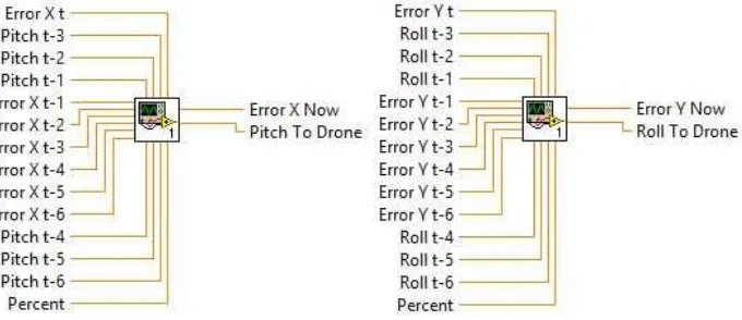
The implementation becomes easier with LabVIEW just as shown in subVI Figure 3:
Figure 3. SubVI pitch control and roll control
3. Results and Discussion
The algorithms are implemented on the AR.Drone, then tested to fly automatically following the reference given indoor. Due to the limitation of length width and height of the room, pitch and roll control signal are restricted in the range ± 0.05 and use 30% of generated signal control.
Flying automatic test procedures are as follwos:
1. Track is used as reference inserted through a front panel that has been created 2. Drone flown to hover at 1 metre height with hover menu on the front panel
3. When hover mode is switch off, the drones will fly automatically following reference given
4. During flying automatically, x-position y-position data and other necessary data are recorded
5. After completing its work, drone will be hover switched back and landed 6. The data obtained will be plotted and analyzed
Figure 4. Experiment with Straight trajectory
The test results show that in general, the controller can do the task well, but it can be seen that the drone is oscillated around the y-axis. From the analysis of error y, sideward velocity and roll control signal is always seen to be late in anticipating error y that result in oscillation. When the error-y close to zero then the control signal generated is also close to zero, but the control signal is not sufficient to reduce the speed of the AR.Drone sideward so AR.Drone will deviate from the reference y. This problem causes the drone to oscillate around the reference y.
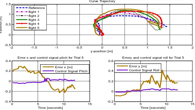
The next test is to provide a reference in the curve trajectory. It is also carried out five times and the results are shown in Figure 5. The test results show that the drones can approach the reference given yet are late when trying to turn following the curve. The control signal is late in responding the sensitive drone movement.
Figure 5. Experiment with Curve Trajectory
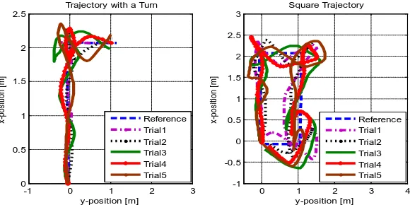
The last test is conducted on tracks with sharp turns and a box shape trajectory. Tests were also done five times and the results are shown in Figure 6.
It is seen that the drone had trouble turning on the track that has sharp curves and a box shape trajectory. Drone always seem to have oscillated in each inflection point toward the next track.
-2 -1.5 -1 -0.5 0 0.5 1 1.5 2 -0.5
0 0.5 1 1.5 2 2.5
y-position [m]
x
-pos
it
ion [
m
]
Straight Reference Trajectory
Reference Trial 1 Trial 2 Trial 3 Trial 4 Trial 5
0 2 4 6 8 10 12
-0.2 -0.1 0 0.1 0.2
Error y, Velocity and Control Signal Roll for Trial 5
Time [seconds]
Error y [m] Sideward Velocity [m/s] Control Signal Roll
-2 -1.5 -1 -0.5 0 0.5 1 1.5 2
-0.5 0 0.5 1 1.5
y-position [m]
x-pos
iti
on [
m
]
Curve Trajectory Reference
flight 1 flight 2 flight 3 flight 4 flight 5
0 5 10 15
-0.4 -0.2 0 0.2 0.4
Error x and control signal pitch for Trial 5
Time [seconds] Error x [m] Control Signal Pitch
0 5 10 15
-0.2 0 0.2 0.4 0.6
Errory and control signal roll for Trial 5
Figure 6. Experiment with sharp turn and box shape Trajectory
4. Conclusion
Generally, H-infinity control for pitch and roll can be used to control the AR.Drone to fly autonomously following various path given. The test results indicate that the controller still has a weakness when there is a sharp turn on the track, and the drone is very sensitive to small changes in control signal. To resolve this problem, use the sideward and forward velocity of drones as inputs of controller might give better results.
References
[1] Pierre-Jean B, Francois C, David V, Nicolas P. The Navigation and Control Technology Inside the AR.Drone Micro UAV. 18th IFAC World Congress. Milano, Italy. 2011.
[2] Krajnik T, Vonasek V, Fiser D, Faigl J. AR-Drone as a Platform for Robotic Research and Education. Research and Eductation in Robotics: EUROBOT. Heidelberg. 2011.
[3] Michael M. The AR.Drone LabVIEW Toolkit: A Software Framework for the Control of Low Cost Quadrotor Aerial Robots. Master of Science Thesis. TUFTS University; 2012.
[4] Emad Abbasi Seidabad, Saeed Vandaki, Ali Vahidin Kamyad. Designing Fuzzy PID Controller for Quadrotor. International Journal of Advanced Research in Computer Science & Technology (IJARCST). 2014; 2(4): 221-227.
[5] Matilde Santos, Victoria Lopez, Franciso Morata. Intelligent Fuzzy Controller of a Quadrotor. IEEE Intelligent Systems and Knowledge Engineering Conf (ISKE). 2010.
[6] Agung Prayitno, Veronica Indrawati, Gabriel Utomo. Trajectory Tracking of AR.Drone Quadrotor Using Fuzzy Logic Controller. Journal Telkomnika. 2014; 12(4): 819-828.
[7] Veronica Indrawati, Veronica Indrawati, Thomas Ardi Kusuma. Waypoint Navigation of AR.Drone Quadrotor Using Fuzzy Logic Controller. Journal Telkomnika. 2015; 13(3): 930-939.
[8] V Indrawati, A Prayitno, G Utomo. Comparison of Two Fuzzy Logic Controller Schemes for Position Control of AR.Drone.7th International Conference on Information Technology and Electrical Engineering (ICITEE). Chiangmai, Thailand. 2015.
[9] Sarah Yifang Tang. Vision-Based Control for Autonomous Quadrotor. Final Report: Undergraduated Senior Thesis. Department of Mechanical and Aerospace Engineering. Princeton University; 2013. [10] Rabah Abbas, Qinghe Wu. Improved Leader Follower Formation Control for Multiple Quadrotors
Based AFSA. Journal Telkomnika. 2015; 13(1): 85-92.
[11] Kruczek A, Stribrsky A. H∞ Control of Automotive Active Suspension with Linear Motor. Proceedings of the 3rd IFAC Symposium on Mechatronic Systems. Sydney, Australia. 2004.
[12] G Raffo, M Ortega, F Rubio. An integral predictive/nonlinear control structure for a quadrotor helicopter. Automatica. 2010; 46(1): 29-39.
[13] GV Raffo, MG Ortega, FR Rubio. Nonlinear H ∞ Controller for the Quad-Rotor Helicopter with Input Coupling. 18th World Congress. IFAC 2011. Milano, Italy. 2011: 13834-13839.
[14] Keita Mori, Katsuya Hotta, Manabu Yamada. Adaptive H ∞ Control for Quad-rotor Helicopters Based on Input Output Linearization. Transactions of the Society of Instrument and Control Engineers. 2014; 50(11): 784-791.
[15] Taesam Kang, Kwang Joon Yoon, Tae-Hyun Ha, Gigun Lee. H-infinity Control System Design for a Quad-rotor. Journal of Institute of Control. 2015; 21(1): 14-21.
-1 0 1 2 3
0 0.5 1 1.5 2 2.5
y-position [m]
x-pos
iti
on [
m
]
Trajectory with a Turn
Reference Trial1 Trial2 Trial3 Trial4 Trial5
0 1 2 3 4
-1 -0.5 0 0.5 1 1.5 2 2.5 3
y-position [m]
x-pos
iti
on [
m
]
Square Trajectory