UNMANNED AIRCRAFT SYSTEMS FOR RAPID NEAR SURFACE GEOPHYSICAL
MEASUREMENTS
Johannes B. Stoll
Mobile Geophysical Technologies, Hannoversche Heerstr.9a, 29221 Celle, Germany [email protected]
Commission I, ICWG I/5
KEY WORDS: Unmanned aircraft system, magnetometry, sensor calibration, UXO-detection, landslide
ABSTRACT:
This paper looks at some of the unmanned aircraft systems (UAS) options and deals with a magnetometer sensor system which might be of interest in conducting rapid near surface geophysical measurements. Few of the traditional airborne geophysical sensors are now capable of being miniaturized to sizes and payload within mini UAS limits (e.g. airborne magnetics, gamma ray spectrometer). Here the deployment of a fluxgate magnetometer mounted on an UAS is presented demonstrating its capability of detecting metallic materials that are buried in the soil. The effectiveness in finding ferrous objects (e.g. UXO, landslides) is demonstrated in two case studies.
1. INTRODUCTION
An important new development in aeromagnetic surveys is the application of unmanned aircraft systems (UAS) or drones. Systems have been developed over the last decade and reached the point of commercial application. Such systems can be used at low altitude and hostile environments that would not allow helicopter surveys. The use of UAS is ideal for collecting very dense data over small grids.
UAS technology is maturing rapidly. It has now reached a level of maturity and user-friendliness that makes it suitable for geophysical mapping applications. Cost and time advantages make UASs a very compelling proposition.
UASs are able to overcome problems in aeromagnetic surveys that arise from changes in the elevation within the survey area. UASs enable using drape flying in which the data is collected at constant terrain clearance. This feature helps to reduce significant differences between flight elevation on adjacent lines and short wavelength noise. It has become much more efficient with the availability of digital elevation models. UAS-borne aeromagnetic surveys allow tighter line spacing and yield more detailed information about exploration targets than from manned aircrafts.
As part of a feasibility study, the components and component performance specifications for the payload required for an autonomous UAS helicopter-magnetometer system was assessed. Existing UAS systems were evaluated for their ability to carry a magnetometer system for flight times of at least 30 minutes. A field evaluation of the noise characteristics for the selected UAS platform was conducted for possible magnetometer placements.
In a pilot project the feasibility was proven for carrying out airborne magnetic measurements and the results were reported by Tezkan et al. (2011). The results of two commercial projects are presented here, which demonstrate the applicability of this innovative airborne technology in near-surface geophysics.
In another pilot project (funded by BMBF) an innovative geophysical measuring system was developed and
tested that makes use of the electromagnetic field radiated by radio transmitter stations. This exploration method enables detection of electrically conductive objects such as cables, pipelines as well as concentrations of copper or iron in the ground. Airborne measurements using the Scout B1-100 from aeroscout gmbh (Lucerne, Switzerland) were successfully conducted on several flight lines in Switzerland and Northern Germany (Eröss et al., 2013)
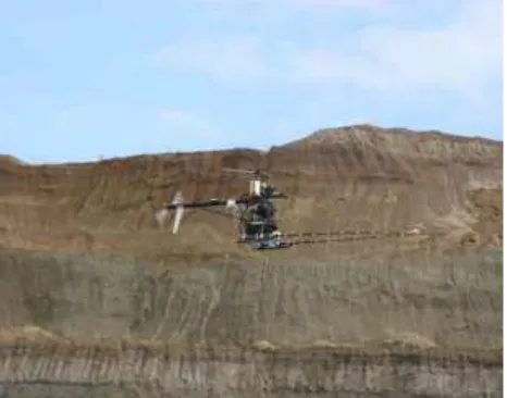
Figure : Gasoline engine driven UAS (Scout B1 aeroscout gmbh, Switzerland) operating in an open pit coal field, Turkey. The magnetometer is mounted on a stinger in front of the UAS.
2. TECHNICAL APPROACH
Many UASs are powered by gasoline engines or turbines, and look to be a very promising alternative for smaller platforms due to large payload capabilities. On the other hand electrical propulsion systems power an increasing number of UASs. There are many benefits of battery powered UASs. An electric UAS has no exhaust noise. The control bandwidth available to the motor can conceivably be used to improve roll axis stability for sensing and targeting. Currently one International Archives of the Photogrammetry, Remote Sensing and Spatial Information Sciences, Volume XL-1/W2, 2013
UAV-g2013, 4 – 6 September 2013, Rostock, Germany
disadvantage of electric propulsion is the quite limited payload capacity of about 1kg.
Unmanned Aircraft systems (UAS) can be characterized and classified in different ways, such as flight altitude, endurance, observability, size, etc. Conceptually, a UAS system has three components: the flight platform, the ground station and a safety controller. Vertical Takeoff & Landing (VTOL) is typically rotary wing. It can initially take off vertically and, therefore, requires very limited space for take-off and landing.
Typically a UAS has an onboard flight computer for control and navigation, GPS for positioning, and magnetometers for orientation. The UAS can be flown semi-autonomously using a PlayStation-like controller if desired, or it can be instructed to follow a flight path (waypoints) completely autonomously.
Figure 1 displays a UAS powered by a piston engine. Its payload capacity is about 15kg and its endurance is about 1 hour. Figure 2 shows a small UAS powered by electric propulsion. Its payload capacity is about 1kg and its endurance also about 1 hour.
Figure Battery driven UAS (md4-1000 microdrones, Germany).
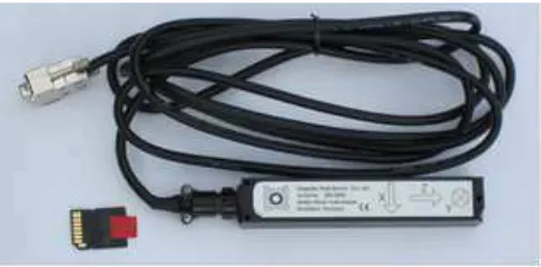
Figure. 3 Light weight data acquisition system.
3. LIGHT WEIGHT FLUXGATE MAGNETOMETER
Several types of sensors exist to measure the magnetic field. Overhauser and optically pumped magnetometers are widely used due to their high resolution of ~0.01 nT and a high sample rate of 10 Hz. Fluxgate vector magnetometers are less used. However, this type of magnetometer has important
advantages over conventionally applied sensors due to their low costs and weight and low power requirements. The main difficulty is to measure, model and correct the three main weaknesses of such magnetometers; calibration errors, non-orthogonalities between axis and lack of sensitivity.
A light weight data acquisition system (Figure 3) was developed to sample the magnetic field sensed by a three-axis fluxgate vector magnetometer (Figure 4) in combination with an inertial measuring unit (gyroscope and GPS sensor). In this combination it enables to keep track of the position, heading and attitude of the fluxgate sensor and provides information about the 3D orientation of the sensor at a time.
Figure 4. Triple axis fluxgate magnetometer and micro SD card.
Specifications
Field range ±100μT
ADC 24bit
sensitivity 0.07 nT @10Hz resolution
power supply
<1 nT
12-18VDC, 150mA serial interface RS232
sample rate 1 - 125 Hz data storage Micro SD Card
Weight 920g
The complete system is compact and easy to deploy. The assemblage to the unmanned aircraft system is straightforward. The whole system consists of the tri-axial fluxgate magnetometer, and an inertial measuring unit (gyroscope, GPS-sensor) to keep track of position and attitude of magnetometer. It is synchronized by GPS clock.
Calibration of the fluxgate sensors provides highest resolution of the magnetic field through elimination of errors due to offsets, non-orthogonalities between the axis of the fluxgate components and gain errors.
Oscillation motion of the magnetometer system hanging below the UAS is a source of inaccurate determination of the position of the sensor while operation. The gyroscope keeps track of and locks the attitude of the magnetometer system. Post-orientation of the magnetometer enables to correct for the exact position above ground.
4. SCALAR CALIBRATION OF VECTOR MAGNETOMETER
The specially-selected magnetometer was acceptance tested to verify sensitivity (gain), sensor noise, non-orthogonality, offset errors. The calibration pit is equipped with a coil system and enables active field compensation (Figure 5). International Archives of the Photogrammetry, Remote Sensing and Spatial Information Sciences, Volume XL-1/W2, 2013
UAV-g2013, 4 – 6 September 2013, Rostock, Germany
The coil system allows cancelling of the external Earth magnetic field and therefore establishes a field free volume with a residual field of less than 1nT. This set up allows determining the sensor offsets, the misalignment between the three sensor axes, and the gain factors.
Once the instrument has been calibrated the parameters are routinely checked by pre-flight calibration. In this calibration the output of the magnetometer is compared with the known magnetic field vector that applies to the instrument.
In order to obtain accurate total magnetic field intensity data from the three axis fluxgate sensor, the scale factors, gains and non-orthogonality angles for each axis must be determined. These nine calibration parameters are initially determined by scalar calibration in the laboratory and refined by comparison with the known total magnetic field intensity (Olsen et al., 2003; Engels et al., 2007). Software calibration of the fluxgate sensors provides highest resolution of the magnetic field through elimination of errors due to offsets, non-orthogonalities between the axis of the fluxgate components and gain errors.
Figure Coil system to calibrate fluxgate magnetometer.
Figure 6 TMI before (blue) and after (red) correction for gain, offset and non-orthogonalities between axes. After correction the TMI is nearly independent from the orientation of the sensor in the magnetic field.
Due to these errors the total magnetic field intensity (TMI) measured by the sensor depends on the orientation with regard to the Earth magnetic field vector. Therefore oscillation motion of the magnetometer hanging below the UAS would result in variations of the TMI. Already a small rotation in a homogeneous magnetic field would generate variations of large amplitudes which cannot be neglected. The effect of the error correction is demonstrated in Figure 6. The figure shows the TMI before and after processing, respectively. The effect of
variations (blue line) is almost cancelled out after application of the correction coefficients (red line).
Oscillation motion of the magnetometer system hanging below the UAS is a source of inaccurate determination of the position of the sensor while operation. The gyroscope keeps track of and locks the attitude of the magnetometer system. Post-orientation of the magnetometer enables to correct for the exact position above ground (Stoll and Virgil, 2009).
5. UXO DETECTION OVER MILITARY CALIBRATION SITE
In collaboration with aeroscout gmbh, Switzerland, a demonstration project on a densely spaced measuring grid with 1 m line spacing was conducted over a military calibration field to determine the typical detection thresholds of ferrous objects and to ascertain the time required from the start of the layout to a finished map. Different types of ferrous objects were detected and localized at a military test site. Figure 7 shows the spatial relationship and the relative size of all magnetic objects. 26 minutes were required to collect the magnetic data along the lines. The total length of the lines is 2100m and the site measures ~2000 square meters. The speed of the UAS was determined to about 2m/s. The sampling rate of the magnetometer was 125Hz which resulted in a measurement being made each 0.02m along the line.
Flight control systems were installed and mission parameters were programmed into the vehicle prior to takeoff. The aircraft is capable of autonomous operation. After take-off it navigated to the pre-programmed waypoints while collecting magnetic data. The residual magnetic anomalies indicate the locations of ferrous objects (UXO) buried in the soil beneath.
Figure7 Residual magnetic field intensity.
6. DETECTION OF MAGNETIC SIGNATURES AFTER A MAJOR LANDSLIDE
A massive landslide occurred in one of the coal-mining districts in Germany and caused the slide of approximately one million cubic meters of soil (Figure 8a, b). The site is the edge of a Lake, a flooded open cast coal mine. The lake is a result of former brown coal surface mining operations. Two houses are vanished into the nearby lake. The landslide caused a massive wake on the Lake, which flooded the surrounding shores and flushed boats onto the banks. The slide increased the water level on the lake by approximately 60 centimeters.
International Archives of the Photogrammetry, Remote Sensing and Spatial Information Sciences, Volume XL-1/W2, 2013 UAV-g2013, 4 – 6 September 2013, Rostock, Germany
UAS-borne aeromagnetic measurements were conducted on a densely spaced measuring grid across the debris of the landslide. The terrain is quite rugged and not accessible.
The survey was subdivided into five sections. The flight time required to complete each section was about 30min. The geomagnetic measuring system consists of a 3-axes fluxgate sensor and a light weight data acquisition system. The sampling rate of the magnetometer was 125Hz which resulted in a measurement being made each 0.05m along the line.
Ground station was installed at the site and mission parameters were programmed into the vehicle prior to takeoff. After take-off the UAS navigated to the pre-programmed waypoints while collecting magnetic data.
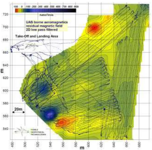
After landing the magnetic data are post-processed, that consists of scaling of the output, calibration, estimation of total magnetic intensity and synchronization with GPS positions. The GPS positions are transformed from WGS84 system into a local coordinate system (Gauss-Krueger-System). The value of the regional field of the IGRF is reduced and the data are low pass filtered. In Fig. below the residual magnetic field corresponding to different kinds of ferrous objects is displayed in a 2D isoline plot.
Figure a, b A landslide washed away parts of a housing development near the former coal mine
7. CONCLUSION
The challenges associated with construction of an effective autonomous UAS magnetometer platform could be resolved successfully and the construction of a successful
autonomous UAS magnetometer platform was feasible. The boom-mounted magnetic system was capable for low-altitude airborne surveys, and can be considered for a wide range of problems where it is critical to detect very small targets, or map geologic properties over large areas. This innovative platform has demonstrated a capability of detection that previously was only possible with man-portable or ground-based vehicle-towed systems. The success of this type of geophysical platform will most likely be determined over the next decade.
Figure 2D-isoline plot of the residual magnetic field. The magnetic data were collected along the tracks on five sections. The clearance between ground and sensor varied between 2 to 5m. The magnetic anomalies reveal the positions of an electric railway engine, the debris mass of family houses and other facilities.
8. REFERENCES
Engels, M, U. Barckhausen, and J. G. Cande, 2008, A new towed marine vector magnetometer: methods and results from a Central Pacific cruise, Geophys. J. Int., 115–
Eröss, R, J.B. Stoll, R. Bergers, and Bülent Tezkan, Three-component VLF using an unmanned aerial system as sensor platform, EAGE, First Break, volume 31, July 2013
Olsen, N., L. Tøffner-Clausen, T. J. Sabaka, P. Brauer, J. M. G. Merayo, J. L. Jørgensen, J. -M. Leger, O. V. Nielsen, F. Primdahl, and T. Risbo, Calibration of the Ørsted vector magnetometer, Earth Planets Space, , 11–
Stoll, J. B., and Ch. Virgil, 2009, Attitude Algorithm Utilised in Mobile Geophysical Measuring Systems. Extended abstract of 23rd Schmucker-Weidelt-Colloquium on Elektromagnetic Depth Sounding, Potsdam, Seddiner See, 28 September - 2 October 2009.
Tezkan, B., J.B. Stoll, R. Bergers, and H. Grossbach, 2011, Unmanned aircraft system proves itself as a geophysical measuring platform for aeromagnetic surveys. EAGE, First Break, 29. April 2011.
International Archives of the Photogrammetry, Remote Sensing and Spatial Information Sciences, Volume XL-1/W2, 2013 UAV-g2013, 4 – 6 September 2013, Rostock, Germany