THE OUTDOOR RAPID CALIBRATION TECHNIQUE AND REALIZATION OF
NON-METRIC DIGITAL CAMERA BASED ON THE METHOD OF MULTI-IMAGE DLT AND
RESECTION
ZHANG Qiang a, SHEN Jian-jing b, SUN Meng-qing c
a Institute of Surveying and Mapping, Zhengzhou Henan 450052, China, [email protected] b
Institute of Surveying and Mapping, Zhengzhou Henan 450052, China, [email protected] c
North China University of Water Resources and Electric Power, Zhengzhou Henan 450046, China, [email protected]
Commission I, WG I/3
KEY WORDS: Non-Metric Camera, Calibration, Multi-Image DLT, Multi-Image Resection
ABSTRACT:
For non-metric CCD digital camera features and the needs of Rapid field non-metric cameras calibration, the error sources was detailed analyzed and a mathematical calibration model has been founded. Both detailed multi-image group iterative method for solving DLT coefficient, the elements of interior orientation and distortion parameters of lens and the multi-image resection method for solving the elements of interior orientation, elements of exterior orientation and distortion parameters of lens have been discussed. A standard steel cage (e.g. Figure 1) has been made for real calibrating non-metric cameras outdoor quickly. In order to verify the accuracy, each method mentioned has been used to solve elements of interior orientation and distortion parameters with the same camera (e.g. Figure 2) and the same test images. The results of accuracy show that the maximum X error was 0.2585mm, the maximum Y error was 0.6719mm and the maximum Z error was 0.1319mm by using multi-image DLT algorithm. On the other hand, the maximum X error was 0.1914mm, the maximum Y error was 0.9808mm and the maximum Z error was 0.1453mm by using multi-image resection algorithm. The forward intersection accuracy of the two methods was quite, and the both were less than 1mm. By using multi-image DLT algorithm the planimetric accuracy was less than 0.2585mm and the height accuracy was less than 0.6719mm. On the other hand, by using multi-image resection algorithm the planimetric accuracy was less than 0.1914mm and the height accuracy was less than 0.9808mm. The planimetric accuracy of resection algorithm was the better than DLT algorithm, but the elevation accuracy of DLT algorithm was the better than resection algorithm. In summary both method can be accepted for non-metric camera calibration. But also the solver accuracy in the inner orientation elements and distortion parameters was not very high has been noted. However for non-metric camera, the true value of inner orientation elements and lens distortion were unknown did not affect the accuracy of photogrammetry.
1. INTRODUCTION
The digital camera is based on the Semiconductor Technology, The Charge Coupled Devices (CCD), which are arrange in a line or a rectangular region square, constitute the imagesensitive linear array or the imagesensitive surface, auxiliary by optical system, mechanical device and electronic circuit's equipment. The digital CCD camera has the volume small, facile, durable, the actual maintenance convenience as well as merits and so on strong earthquake resistance ability. More importantly, speaking of the digital CCD sensor's character and the sensitivity, it can be stability for a long time. This means that the digital CCD camera may be calibrated(Wang Lei, 2002). The GDOP of digital CCD camera’s focal plane decides in these photoconductive cells’s geometry position precision. Each photoconductive cell is equal to a pixel, it records a single color value, forms a picture element, and all picture elements form an image. A digital CCD camera's big advantage is each element's position does not change. Therefore it does not need to use the collimation marks to determine the CCD camera's internal relevant position. Otherwise the film is not so, it has the film distortion error.
There are two types digital cameras can be use for photogrammetry: metric digital camera and non-metric digital camera. With the rapid development of science and technology, the performance of normal non-metric digital camera is increasingly enhanced, which easy satisfies many photographic conditions with a low cost. Therefore, the digital camera is used to the close-range photogrammetry widely. But in generally
speaking, the elements of interior orientation are unknown and the lens distortion is too bigger for normal non-metric digital camera. These shortcomings badly influence measurement accuracies. Recently the research of non-metric digital camera calibration was more and more.
In the literature that I have seen(HE Min, 2011a)(Miao Hongjie, 2005), in the digital camera calibration, which generally is based on outdoor standardization field or indoor standardization field, we can obtain elements of interior orientation and/or the lens distortion by solute the resection equation or direct linear transformation (DLT) equation. When we solute interior orientation parameters and lens distortion parameters simultaneously in three dimension with multi-Images, we find it difficult.
In this paper, we has founded two mathematical model of the camera calibration, put forward the adoption of the multi-images iteration method to calculate the coefficients of the DLT/resection and distortion parameters in groups by three-dimensional ground control points (GCP), The precision of camera calibration are confirmed by the experiments of multi-image resection and forward intersection, and the satisfactory effect is obtained.
2. ANALYSIS OF ERROR SOURCES
The errors which the digital CCD camera produces are mainly divided into the spectrum error and the geometrical error. The spectrum error, which is mainly caused by CCD, consists of
background noise, accidental noise and invalid pixel. The geometrical error mainly is produces by its optics lens and the image sampling circuit. The geometrical error divides into optics error and the electricity error generally. Then we introduced separately the CCD camera produces spectrum error and geometrical error's analysis and examination.
2.1 Spectrum Error
2.1.1 Determination and Elimination of Background Noise: When the camera lens cap is close and the f-number is 22, we release the shutter and get a gray matrix from the photo. This matrix is called background noise. Background noise can affect signal-noise ratio of the digital image. A good camera and the sampling system should have a low amplitude and uniform background noise. The way of eliminating the background noise is to use current image to subtract its background noise.
2.1.2 Elimination of Accidental Noise: The accidental noise is presents the random along with the time change gradation step change, when carries on the examination, may absorb many phantoms continuously to the identical scenery. Takes its gradation average value to take the final grey level, like this may eliminate the accidental noise effectively the influence.
2.1.3 Elimination of Invalid Pixel: The CCD maybe exist individual damage cell or the cell of physical character is unstable. This kind of cell is called invalid pixel. The way of Elimination is to interpolate this invalid pixel by the neighbouring pixel
2.2 Geometrical Error
The geometrical error of the digital CCD camera mainly refers to the lens distortion error. It includes the radial distortion error and the tangential distortion error. The lens distortion error generally performs for the centre small and peripheral big. The radial distortion error is
⎪⎩ ⎪ ⎨ ⎧
+ + + −
= Δ
+ + + −
= Δ
) )(
(
) )(
(
6 3 4 2 2 1 0
6 3 4 2 2 1 0
L L
r k r k r k y y y
r k r k r k x x
x (1)
The tangential distortion error (Shao Xihui, 1991) is
⎪⎩ ⎪ ⎨ ⎧
− − + − + = Δ
− − + − + = Δ
) )( ( 2 ] ) ( 2 [
) )( ( 2 ] ) ( 2 [
0 0 1 2 0 2
2
0 0 2 2 0 2
1
y y x x p y
y r p y
y y x x p x
x r p
x (2)
where 2
0 2
0) ( )
(x x y y
r= − + − x, y = pixel coordinates
x0, y0 = principal point of photograph coordinates k1, k2, k3…= radial distortion coefficients p1, p2, = tangential distortion coefficients
3. CALIBRATION ALGORITHM OF MULTI-IMAGE DLT
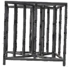
The indoor specialized optics check-out facility and the outdoor standardization field are two general methods of calibration. However, this paper has used a standard portable steel cage outdoor, which is approximately 50cm long, 50cm wide and 50cm high. It has six levels of elevation differences altogether
approximately 50cm and altogether 61 control points. This site is presented in Figure 1.
Figure 1 Standard Portable Steel Cage
For the non-metric digital camera, the principal-distance f is unknown and it has not collimating marks. Therefore DLT, which founds the relationship between the photo coordinate system and the ground coordinate system, is direct algorithm without the elements of interior orientation. It is very fit for the calibration of digital camera. However, the traditional DLT is low precision and not easy to converge. So solution is to be difficult. When the control points have small altitude difference, we can not synchronously obtain elements of interior orientation and the lens distortion by solute the DLT equation. So we put forward the adoption of the multi-images iteration method to calculate the coefficients of the DLT and distortion parameters in groups by three-dimensional ground control points (GCP). The precision of camera calibration are confirmed by the experiments of multi-image resection and forward intersection, and the satisfactory effect is obtained.
3.1 Improved DLT with Distortion Error Correction
The DLT equation with distortion error correction is
⎪ ⎪ ⎩ ⎪⎪ ⎨ ⎧
= + +
+ + +
+ + Δ + −
= + +
+ + +
+ + Δ + −
0 1
0 1
11 10 9
8 7 6 5 0
11 10 9
4 3 2 1 0
ZL YL XL
L ZL YL XL y y y
ZL YL XL
L ZL YL XL x x x
(3)
where X, Y, Z = GCP coordinates L1, L2, L3…= DLT coefficients
△x , △y = distortion coefficients
It is obvious that we can calculate the DLT coefficients and the distortion parameters with some control points from Eq. (3). If we ignore high order terms of Eq. (1), the distortion parameters are k1, k2, k3, p1, p2. We need 8 control points at least to solve the 11 DLT coefficients and 5 distortion parameters.
3.2 Solution of the DLT Coefficients
Observation equation is
⎪ ⎪ ⎩ ⎪ ⎪ ⎨ ⎧
= Δ + ′ − Δ + ′ − Δ + ′ −
Δ + ′ − + + + −
= Δ + ′ − Δ + ′ − Δ + ′ −
Δ + ′ − + + + −
y x
v A y y A y y Z L A y y Y L
A y y X L A L Z L Y L X L
v A x x A x x Z L A x x Y L
A x x X L A L Z L Y L X L
/ ) ( / ) ( / ) (
/ ) ( / ) (
/ ) ( / ) ( / ) (
/ ) ( / ) (
11 10
9 8 7 6 5
11 10
9 4 3 2 1
(4)
Type of Matrix is
L C
V = Δ+ (5)
where
Normal equation is
0
3.3 Solution of the Distortion Parameters and elements of interior orientation
For weakening the influence of correlation between DLT coefficients and principal point of photograph, we regard
x
0and
y
0 as undetermined parameters. From the Eq. (3) and the Eq. (4) we can obtain the following equation⎪
Normal equation is
0
4. CALIBRATION ALGORITHM OF MULTI-IMAGE RESECTION
4.1 Single Image Resection with Distortion Correction
Because the collinear equation is non-linear transformations, the collinear equation can be linearized for solving orientation parameters. The linearization considers the Taylor series first-order expansion of collinear equation collinear equation at the Initial value. The linearized collinear equation with distortion error correction (Chen Xingfeng, 2011b) is
0
From the Eq. (10) we can obtain the following observation equation
⎪
Normal equation is
0
4.2 Multi-Image Resection with Distortion Correction
Since the single image resection using only one photo and fewer geometric constraints and fewer observed values to solve the parameters, furthermore the outdoor calibration portable cage is too small to cover the whole image even only half image, it is not easy to achieve the optimal solution. The interior orientation elements and the exterior orientation elements and the distortion error parameters are strongly correlated, so that the stability and reliability of calibration results become poor. However the solving accuracy of multi-image resection is better than the single image resection. The most important difference between them is taking many images of calibration portable cage in photo’s different position. They have the same interior orientation elements and distortion error parameters, but the different exterior orientation elements. This is equivalent to increase not only redundant observation, but also greatly reduce the influence of correlation between the interior orientation elements and exterior orientation elements, but the negative effects are unknown parameters of error equation rapidly increase as the number of images, so that the works of calculation become too large and the higher precision initial values. Otherwise the iterative calculation time become longer, even not converge.
The basic resection algorithm of single image is the same as multi-image. The only difference is that used more than one photo to solve the same interior orientation elements and distortion error parameters. Let the number of images equal to n and the number of GCPs is m. we can obtain the following observation equation
0 = − + +BF DG L
AE (14) where Ai= coefficient matrix of exterior orientation
Bi = coefficient matrix of interior orientation Di = coefficient matrix of distortion parameters
T i i i iS iS iS
i dX dY dZ d d d
E =[ ϕ ω κ]
[
]
Tdy dx df
F= 0 0
[
]
Tp p k k k
G= 1 2 3 1 2
0 ... ...
... ... ...
1 2 3 2 1
1 5 3 2 1
1 3 3 2 1
1 6 3 2 1
6 2 3 2 1
=
⎥ ⎥ ⎥ ⎥ ⎥ ⎥
⎦ ⎤
⎢ ⎢ ⎢ ⎢ ⎢ ⎢
⎣ ⎡
−
⎥ ⎥ ⎥ ⎥ ⎥ ⎥
⎦ ⎤
⎢ ⎢ ⎢ ⎢ ⎢ ⎢
⎣ ⎡
+
⎥ ⎥ ⎥ ⎥ ⎥ ⎥
⎦ ⎤
⎢ ⎢ ⎢ ⎢ ⎢ ⎢
⎣ ⎡
+
⎥ ⎥ ⎥ ⎥ ⎥ ⎥
⎦ ⎤
⎢ ⎢ ⎢ ⎢ ⎢ ⎢
⎣ ⎡
⎥ ⎥ ⎥ ⎥ ⎥ ⎥
⎦ ⎤
⎢ ⎢ ⎢ ⎢ ⎢ ⎢
⎣ ⎡
× ×
× ×
×n n n n n n n n m m
n L
L L L
G
D D D D
F
B B B B
E E E E
A A A A
observation equation is
⎪ ⎪ ⎪ ⎩ ⎪⎪ ⎪ ⎨ ⎧
− + + =
− + + =
− + +
= + + −
=
n n n n n
n AE BF DG L V
L G D F B E A V
L G D F B E A V
L G D F B E A V
...
3 3 3 3 3 3
2 2 2 2 2 2
1 1 1 1 1 1
(15)
That is
m
n n n m n n n
m L
G F E E E E
D B A
D B A
D B A
D B A
V 2
1 ) 8 6 ( 3 2 1
) 8 6 ( 2 3 3 3
2 2 2
1 1 1
2 ...
0 0 0 0
... ... ...
0 0 0 0
0 0 0 0
0 0 0 0
−
⎥ ⎥ ⎥ ⎥ ⎥ ⎥ ⎥ ⎥ ⎥
⎦ ⎤
⎢ ⎢ ⎢ ⎢ ⎢ ⎢ ⎢ ⎢ ⎢
⎣ ⎡
⎥ ⎥ ⎥ ⎥ ⎥ ⎥
⎦ ⎤
⎢ ⎢ ⎢ ⎢ ⎢ ⎢
⎣ ⎡
=
× + + ×
(16)
There are 6n+8 variables, so at least 3n+4 GCPs are need to solve Eq.(16). Type of Matrix is
L C
V = Δ+ (17)
5. THE RESULTS OF EXPERIMENT
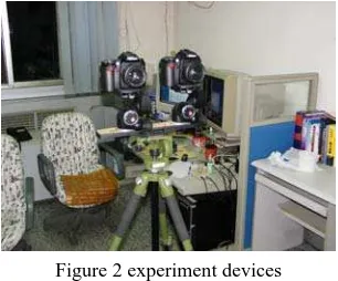
This experiment used a Manfrotto tripod and the two Nikon D90 digital cameras with NIKKOR AF-S DX lens in each, image size: 23.6mm×15.8mm, effective pixels: 4288×2848, focal length: 36mm, pixel size: 0.0055mm. e.g. Figure 2
Figure 2 experiment devices
To prevent the small change of focal length to influence interior orientation element stability, we had fixed focal length in the experiment. In order to compare the experimental results, we used multi-image resection and DLT algorithm to solve interior orientation and the distortion parameter respectively. Both of them used the data of outdoor portable calibration steel cage.
Figure 2 Standard Portable Steel Cage
Figure3 UI of Calibration Software Fix two cameras,
tripod and calibration cage
Use Camera I to take images
Multi-image DLT and resection
Forward intersection with stereo images Use Camera II to take images
The calibration experimental was done in two steps, e.g. Figure 2. The first step, after two cameras and a tripod and a calibration cage were fixed, many multi-angle pictures were taken to solve each camera’s interior orientation elements and distortion parameters, with multi-image DLT and resection independently. Table 1 gave the result of calibration and comparison.
DLT Resection
Camera I Camera II Camera I Camera II
mm mm mm mm f 36.134391 36.074060 36.3144857 36.3802218 x0 0.377716 -0.029422 0.09867725 0.16534004 y0 0.132797 0.128374 0.04919723 -0.14494807 k1 1.209E-004 2.212E-004 1.5803E-04 1.5203E-04 k2 9.149E-007 -7.742E-007 2.2004E-07 1.1079E-07 k3 -8.902e-009 5.002e-010 6.7031E-10 2.31E-10 p1 -7.787e-005 -8.151e-005 4.8981E-06 2.7895E-05 P2 2.016e-005 -2.450e-005 2.1424E-06 1.7463E-05 Table 1. The Result of Interior Orientation and Distortion
Parameters
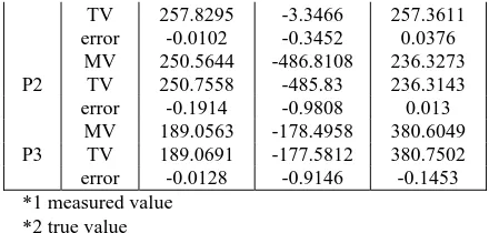
The second step, a pair of stereoscopic images were used to compare the accuracy of forward intersection. The resection result of this stereoscopic pair was showed in table 2 and the forward intersection's result of stereoscopic pair was showed in Table 3.
DLT Resection
Camera I Camera II Camera I Camera II mm mm mm mm
XS 91.0592 439.4953 89.7228 439.5092
YS 1917.5416 1918.3010 1914.8721 1918.4376
ZS 276.7085 265.5823 276.7437 265.7132
ϕ 0.2568 3.2346 0.2929 3.2381
ω 1.4074 0.1787 1.4107 0.1758
κ 1.8234 2.0439 1.8200 2.0437
MSE x 0.0023 0.0026 0.0037 0.0027
MSE y 0.0024 0.0038 0.0043 0.0040
Table 2. The Result of Multi-Image Resection
GCP X
mm
Y mm
Z mm DLT
MV*1 258.0880 -4.0185 257.3924 TV*2 257.8295 -3.3466 257.3611 P1
error 0.2585 -0.6719 0.0313
MV 250.8088 -485.2394 236.1824
TV 250.7558 -485.83 236.3143
P2
error 0.0530 0.5906 0.1319
MV 189.2726 -178.0339 380.8347 TV 189.0691 -177.5812 380.7502 P3
error 0.2035 -0.4527 0.0845 Resection
P1 MV 257.7273 -3.6918 257.3987
TV 257.8295 -3.3466 257.3611
error -0.0102 -0.3452 0.0376
MV 250.5644 -486.8108 236.3273
TV 250.7558 -485.83 236.3143
P2
error -0.1914 -0.9808 0.013
MV 189.0563 -178.4958 380.6049
TV 189.0691 -177.5812 380.7502
P3
error -0.0128 -0.9146 -0.1453
*1 measured value *2 true value
Table 3. The Result of Forward Intersection
6. CONCLUSION
The results of accuracy show that the maximum X error was 0.2585mm, the maximum Y error was 0.6719mm and the maximum Z error was 0.1319mm by using multi-image DLT algorithm. On the other hand, the maximum X error was 0.1914mm, the maximum Y error was 0.9808mm and the maximum Z error was 0.1453mm by using multi-image resection algorithm.
The forward intersection accuracy of the two methods was quite, and the both were less than 1mm. By using multi-image DLT algorithm the planimetric accuracy was less than 0.2585mm and the height accuracy was less than 0.6719mm. On the other hand, by using multi-image resection algorithm the planimetric accuracy was less than 0.1914mm and the height accuracy was less than 0.9808mm. The planimetric accuracy of resection algorithm was the better than DLT algorithm, but the elevation accuracy of DLT algorithm was the better than resection algorithm.
In summary both method can be accepted for non-metric camera calibration. But also the solver accuracy in the inner orientation elements and distortion parameters was not very high has been noted. However for non-metric camera, the true value of inner orientation elements and lens distortion were unknown did not affect the accuracy of photogrammetry.
REFERENCES
Wang Lei, J., 2002. Master Thesis, Application and research of digital close-range photography, In: Institute of Surveying and Mapping, Information Engineering University,.Zhengzhou, China,pp 35-48.
Miao Hongjie, J., 2005. Discussions on the issues in calibration of digital cameras and photogrammetry. Journal of Capital Normal University(Natural Science dition), 36(1), pp. 117-120. HE Min, J., 2011a. The tesearch on several methods of camera calibration, Journal of Geomatics & Spatial Information Technology, 34(6), pp. 275-277.
Shao Xihui, J., 1991. M. engineer photogrammetry. Institute of Surveying and Mapping press, Zhengzhou, China, pp. 76-122.
Chen Xingfeng, J., 2011b. Multi-Image space resection based geometric calibration for the four band CCD camera, Journal of Remote Sensing For Land & Resources, 1, pp 21-24.