UNIVERSITY OF ZAGREB
FACULTY OF MINING, GEOLOGY AND PETROLEUM ENGINEERING Graduate study of mining engineering
PAPER RECYCLING
Master thesis
Mate Juraj Kalinić R-99
University of Zagreb Master’s Thesis Faculty of Mining, Geology
and Petroleum Engineering
PAPER RECYCLING MATE JURAJ KALINIĆ Thesis completed in: University of Zagreb
Faculty of Mining, Geology and Petroleum engineering Department of Mining and Geotechnical Engineering Pierottijeva 6, 10 002 Zagreb
Abstract
Wood is the main material for paper production and with high costs of raw material paper mills are searching for other materials for paper production. With a higher demand for paper, waste paper is being used more and more as the main material for paper production. To be able to use waste paper in paper production we must pulp it, remove all contaminants and deink. In paper recycling plants a huge problem is waste water due to the high water consumption. Waste water from paper recylcling is treated in different ways then reused in the recycling process.
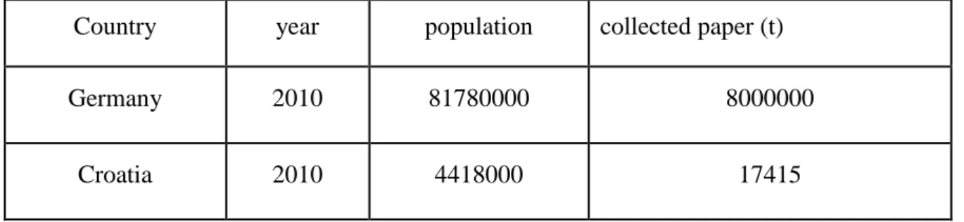
Croatia’s waste paper recovery rate is one of the lowest in the European union and in 2010 was only 3,97 kg per person. Improving the recovery rate could be done by introducing new technologies in watse paper collection i.e. modern trucks for waste paper collection.
Keywords: Paper, recycling, deinking, pulping, waste water treatment
Thesis contains: 52 pages, 3 tables, 12 figures and 24 references.
Original in: English
Thesis deposited in: Library of Faculty of Mining, Geology and Petroleum Engineering, Pierottijeva 6, Zagreb
Supervisor: Gordan Bedeković, PhD, Associate Professor
Reviewers: Gordan Bedeković, PhD, Associate Professor.
Ivan Sobota, PhD, Assistant Professor Želimir Veinović, PhD, Assistant Professor
Sveučilište u Zagrebu Diplomski rad Rudarsko-geološko-naftni fakultet
RECIKLIRANJE PAPIRA MATE JURAJ KALINIĆ
Diplomski rad je izrađen: Sveučilište u Zagrebu
Rudarsko-geološko-naftni fakultet Zavod za rudarstvo i geotehniku Pierottijeva 6, 10000 Zagreb
Sažetak
Drvo je glavna sirovina za proizvodnju papira, te s visokim troškovima ulazne sirovine, tvornice papira su u potrazi za drugim materijalima za proizvodnju papira. S povećanjem potražnje papira, otpadni papir se sve više i više koristi kao glavna sirovina u proizvodnji novog papira. Kako bi se otpadni papir mogao koristiti u proizvodnji potrebno ga je provesti u pulpu te odstraniti sve nečistoće i tintu. Zbog velike potrošnje vode u postrojenjima za reciklažu papira veliki problem je otpadna voda. Ona se pročišćava na razne načine te se ponovno koristi u procesu recikliranja. Povrat otpadnog papira u Hrvatskoj je praktično na najnižoj razini u Europskoj Uniji, a 2010. godine iznosio je samo 3,97 kg po osobi. Unapređenje povrata starog papira moglo bi biti poboljšano uvođenjem novih tehnologija u prikupljanju otpadnog papira npr. suvremenijim kamionima za njegovo sakupljanje.
Ključne riječi: Papir, recikliranje, ukljanjanje boje, pulpiranje, obrada otpadne vode
Završni rad sadrži: 52 stranica, 3 tablice, 12 slika i 24 reference
Jezik izvornika: engleski
Završni rad
pohranjen: Knjižnica Rudarsko-geološko-naftnog fakulteta
Pierottijeva 6, 10000 Zagreb
Voditelj: Dr. sc. Gordan Bedeković, izvanredni profesor RGNF-a
Ocjenjivači: Dr. sc. Gordan Bedeković, izvanredni profesor RGNF-a
Dr. sc. Ivan Sobota, docent RGNF-a Dr. sc. Želimir Veinović, docent RGNF-a
CONTENTS
LIST OF FIGURES ... V LIST OF TABELS………...VI LIST OF ABBREVIATIONS……….VII
1. Introduction ... 1
2. The History of Paper ... 3
3. PULPING ... 5
3.1. Mechanical Pulping ... 5
3.2. Thermo-chemical pulping ... 6
3.3. Chemical pulping ... 6
4. The paper making process ... 8
5. Types of Paper ... 9
6. Methods of paper collection ... 10
6.1. Paper collection within the EU ... 10
6.2. Paper collection in China ... 14
7. Processing Wastepaper ... 16
7.1.Wastepaper preparation and contaminant removal ... 16
7.1.1.Pulping ... 16
7.1.2. Low-consistency pulping ... 17
7.1.3. High-consistency pulping ... 18
7.1.5. Screening and cleaning ... 19
7.1.6. Screening ... 20
7.1.7. Centrifugal cleaning... 21
7.1.8. Dispersion ... 23
7.1.8. Types of dispersion and kneading units ... 24
7.2. Deinking ... 26
7.2.1. Wash deinking ... 27
7.2.2. Pulping conditions ... 27
7.2.3. Wash conditions ... 27
7.2.4. Equipment used in wash deinking ... 28
7.2.5. Flotation deinking... 29
8.Water and waste water treatment in recycling mills ... 31
8.1. Freshwater use in recycling ... 31
8.1.1. Freshwater treatment ... 32
8.2. Effluent loads ... 33
8.3. Effluent Treatment Standards ... 33
8.4. Physiochemical Treatment process- Waste Water Clarification ... 34
8.4.1. Pre-treatment ... 35
8.4.2. Sedimentation ... 36
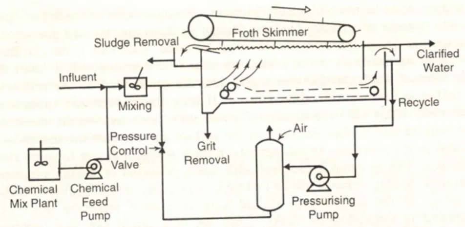
8.4.3. Dissolved air floatation (DAF) ... 36
8.4.4. Filtration ... 37
8.5. Biological Treatment systems ... 37
8.5.1. Anaerobic treatment process ... 37
8.5.2. Anaerobic process microbiology ... 38
8.5.3. Aerobic treatment processes ... 38
8.5.4. Activated sludge ... 38
8.6. Sludge treatment and disposal ... 38
8.6.1 Sludge collection and blending ... 39
8.6.3.3. Landfill ... 41
8.6.3.4. Other stabilisation processes ... 41
8.7. Chemical use in water clarification and effluent treatment ... 42
8.7.1. Chemical use in freshwater clarification ... 42
8.7.2. Recycling mill backwater clarification ... 42
8.7.2.1. Flocculation and coagulation ... 43
8.6.2. Nutrients-nitrogen and phosphorus ... 44
9. Paper collection and improvement possibilities in Croatia ... 45
LIST OF FIGURES
Figure 2-1. Diagram of Bryan Donkin’s paper machine, circa 1804 (Bierman, 1996). ... 4
Figure 3-1. Variations of the Stone Ground wood process of mechanical pulping. (Holik, 2013) ... 6
Figure 4-1., The paper making process (Holik, 2013)... 8
Figure 7-1. High consistency pulper (JMC machines, 2015) ... 19
Figure 8-1. Fresh water circuit diagram (Mc Kinney, 1995)... 32
Figure 8-2. Water loop, packing grade schematic (Mc Kinney, 1995) ... 34
Figure 8-3. Dissolved air flotation clarifier schematic (Mc Kinney, 1995.) ... 36
Figure 9-1. Municipal waste treatment in European union by category 2011. (Mc Carthy, 2013) ... 46
Figure 9-2. The Roto-press truck (FAUN Kirchhoff grupe, 2015) ... 47
Figure 9-3. A Raptor Side Lift truck; note the side lift mechanism on the truck to lift the plastic containers (Mitch, 2011). ... 48
Figure 9-4. A typical plastic container that can be lifted with the Raptor Side Lift (Cherry plastics, 2008) ... 48
Figure 9-5. An example of the inside of the cabin of a Raptor Side Lift truck (MitchellM15, 2013). ... 49
LIST OF TABLES
Table 1-1 UK Standard Waste Paper Groups EN643 (Lets recycle: Paper grades and EN6433, 2014). ... 11 Table 1-2 CEPI Standard waste paper groups (Lets recycle: Paper grades and EN6433, 2014). ... 13 Table 1-3 Comparison of collected paper and population (Agencija za zaštitu okoliša, 2011 and Euorpean environmental agency, 2013) ... 45
LIST OF ABBREVIATIONS
RH - Relative humidity SGW - Stone ground wood TCP - Thermo chemical pulping CMP - Chemi-mecanical pul
CTMP - Chemi-thermomechanical pulp ECF - Elemental chlorine free
COD - Chemical oxygen demand BOD - Biological oxygen demand DAF - Dissolved air flotation
1. Introduction
Paper is a commodity that people use every day without even realizing it, for example when someone goes shopping and receives a paper bag or a receipt; when students write in school; when one is wrapping presents, and most importantly when everyone goes to the toilet. It is a product that is taken for granted and it would be hard to imagine a life without it. Paper is one of the most versatile materials that man has created and paper has many uses from packaging products for transport to even being used as a building material where it is used as a material base for building homes during the great depression in the USA (Rudin, 1968).
Nowadays most of the paper that is used, is actually recycled paper (Paper for Recycling: facts and figures, 2014). This is because of not only the environmental benefits but all the low cost in comparison to raw material in the paper making production.
Currently the benefits to the environment of paper production from recycled materials in comparison to paper production from primary sources is not a black and white issue. Although newer studies have shown with the incorporation of advanced technology in the process of paper production from secondary sources there are more benefits to the environment. The benefits are the use of less energy and water in the production process, saving forest, reducing landfill and less air pollution.
On average, the production of virgin fibre paper, followed by incineration uses twice as much energy than it takes to produce recycled paper.“Recycling paper uses 60% less energy than manufacturing virgin timber paper“ (Statistics, 2015). In Europe, 70% less energy is required for secondary manufacturing of paper than using a primary source (Confederation of European Paper Industries, 2011).
Paper manufacturing is the largest industrial user of water per pound of finished product. (ID2 comunications). Conventional paper manufacturing processes require 40m3 of water to produce one tonne of paper, most of which is a result of manufacturing virgin pulp. By re-using fibres, manufacturing recycling paper consumes around 24 m3 per tonne- a saving of approximately 47%. (ID2 comunications). The European paper industry is
The use of wood solely from plantation forests addresses concerns about loss of old growth forests. A fibre can be recycled several times, yet not indefinitely, depending on the paper grade, therefore there is a continous need to feed the inflow of recovered fibre with paper products made of virgin pulp. Producing paper from a secondary source can reduce harvesting by reducing demand for pulpwood.
The task of this thesis is to show the production of paper with raw materials (wood) and in particular the use of waste paper for producing recycled paper. An explanation of how the waste paper is used in the production of paper and a distribution of the actual process to making the paper. Also, the treatment of water and waste after paper recyling will be mentioned.
In this paper we will compare waste management in the European union, China and Croatia, aswell as comparing collection of waste paper in Australia and Croatia. From this comparison we hope to improve waste management of waste paper by using the advancement of tehnology and society that are mentioned.
2. The History of Paper
According to legend, Tsai Lung a high official in the court of Hun invented paper after observing how wasps construct their nest using a similar material. Whilst, this may not be entirely true the fact remains that Tsai Lung in 105AD codified paper and became its’ official inventor in history. However, there is proof that paper existed even before that and the earliest mention of paper dates back to 206BC (Corente, 2004).
The first types of material used to create paper were plant based i.e. rice, bamboo, straw and bark. This proved to be a successful choice since they contain high content of cellulose; a natural polymer, which allowed paper to be as versatile like it remains today. Western civilization can thank the Arabs for bringing paper to Europe. In 751 AD the Arabs had first contact with paper after conquering Turkistan which was a part of China. The Arabs realized the potential of paper in a business sense. The Arabs started trading paper throughout the Mediterranean basin and later on established paper mills first in Baghdad around 794/795 AD and, then later on in the territories in Andalusia, Sicily, Malta and France (Corente, 2004). These paper mills proved to be strategically placed since they were located on major trade routes, and resources used to produce paper abundant i.e. forests and rivers. In the meantime, the Arabs also improved the quality of paper by mixing it with more durable materials like cotton, cloth and hemp. This increased the hardiness of the paper produced and this kind of paper is still produced today.
The true potential of paper was realized when Gutenburg invented the printing press. Because of this invention there was a steady increase of the demand of paper. However, around the time of the Industrial Revolution there was a sudden increase off the demand of paper. The reason being that paper was used in the manufacturing and packaging process of goods and education started playing a more vital role in society which meant that it was not anymore for reserved the elitist classes anymore.
The most important milestone for the paper industry was the development of the paper machine. In 1799, Louis Robert obtained French patent rights for his machine (Bierman, 1996). Later on in 1801, two brothers Henry and Sealy Fourdrinier bought the
Figure 2-1. Diagram of Bryan Donkin’s paper machine, circa 1804 (Bierman, 1996). Within a couple of years there was rapid improvement with the development of the paper machine and soon the only thing limiting the amount of paper produced was the fiber supply. Which is why around 1865 wood replaced rags to become the main material used in the production of paper. The reason wood was chosen was because it was easily mechanized to extract the fibers for the mass production of paper and paperboard materials which was required in order to meet the high demand of the consumer.
Once again, paper production in developed countries is being limited to the fiber supply. Gone are the days when huge logs would go directly to the paper mills and the price of raw fiber has risen to such extremes that paper mills are trying to find new recyclable sources of fiber to create paper. Since the 1960s recycled paper is playing a more important role in the production of paper. However, paper recycling has been around much longer; in Japan the oldest recycled paper was found and dated back to 1031 AD (Corente, 2004). Today recycled paper pulp represents 41.6% of all paper production since the pulp is used in the production of carton, paper packages, magazine and journals just to name a few products that main material is recycled paper pulp (Paper for Recycling: facts and figures, 2014).
3. PULPING
3.1. Mechanical Pulping
Since 1880 the most commonly used substance for creating paper is wood. The reason being that the cellulose fibers located in wood, a complex polymer better known as lignin is hard, brittle and an easy to manipulate material which makes it ideal for paper. Separating the fiber lignin from the rest of the wood is known as pulping. Pulping can either be a mechanical or a chemical process.
Mechanical pulping today constitutes 20-25% of paper production. It is mainly used for non-permanent papers such as news print and catalog paper due to the high yield and the quality of the end product.
Mechanical pulping as its name implies is the application of mechanical force to the wood in a crushing or grinding manner; which in turn generates heat and softens the lignin leading to the separation of individual fibers (Bierman, 1996). Since mechanical pulping does not remove the lignin, therefore, the yield of the pulp from the wood is quite high. Moreover, the fibers are hard and stiff often being described as dimensionally more stable; basically meaning, that the cellulose fibers absorb moisture from the atmosphere when the relative humidity (RH) is high and loses moisture when the RH is low. This is followed with dimensional changes which are reduced when the material is coated with fibers like lignin. The finished product of mechanical pulping separation have the notion of high bulk with low density i.e. for any given thickness a relatively low weight per unit of area.
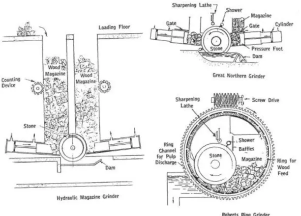
Mechanical pulping at its most basic form involves forcing a tree trunk against a rotating grinding surface is still used in some paper mills in present day. The above mentioned process uses a vast amount of energy and the end result is an extremely high-yield product call Stone Ground Wood (SGW) pulp (Figure 3-1.) An alternative method of softening lignin is by using heat or by using the ability of certain chemicals. This directly reduces the amount of mechanical energy that is needed for the fiber separation during pulping and the reduction of damage to fibers; thus, creating a higher quality pulp.
Figure 3-1. Variations of the Stone Ground wood process of mechanical pulping. (Holik, 2013)
3.2. Thermo-chemical pulping
Thermo-chemical pulp (TCP) is a method in which wood in chip form is heated prior or during the process of pulping. Applying certain chemicals i.e. sodium sulphite; sodium hydroxide or oxalic acids is better known as chemi-mechanical pulp (CMP) and when the two processes of pulping are combined the process is called chemi-thermomechanical pulp (CTMP) (Bierman, 1996). Mechanical pulp retains the colour of the original wood were as through CTMP more lignin is removed thus making the end product slightly lighter.
3.3. Chemical pulping
Chemical pulping is the use of chemicals for the separation of fibers by the dissolving the non-cellulose and non-fibrous components of the wood. The two main chemical processes are characterized by the name of the type of chemical cocktail used. The Sulphate or Kraft process is the use of strong alkali and is the most used because of the
versatility of the process since all the main types of wood and chemicals can be re-used and recovered. Suphite process is the second main process, which is a strong acid is used. In both chemical pulping processes the non-cellulose and is further used as the main source of energy in the pulp mill which now are called integrated mills since they manufacture on the same site both pulp and paper/paperboard. The percentage of wood fibers in chemically separated pulp is 74% which is lower than mechanically separated pulp. The underlying reason being that the non-cellulose constituents of the wood were removed during the pulping process. The pulp can undergo a high degree of interfibre bonding, which directly results in a stronger and more flexible sheet of paper.
Chemically separated pulp can be whitened or bleached by processes which remove the residual lignin and any other traces of wood-based material. Even though the individual cellulose fibers are translucent and colourless, bleached pulp has a white colour. Bleaching is an aspect of the paper manufacturing industry that has been subject to much criticism on environmental grounds. This is due to a by-product of the bleaching process the chloro-organic substances that are released from mills where chlorine gas is used to treat pulp. However, in modern times this criticism is no longer valid since the main bleaching process is elemental chlorine free (ECF) and uses a combination of oxygen, hydrogen-peroxide and chlorine dioxide in which the by-products are simple and harmless to the environment.
4. The paper making process
After the pulping process, the pulp is further refined using a mechanical treatment to obtain the optimum papermaking properties of the pulp. Refining increases the strength of the fiber and the interfibers bonds; since it increases the surface area of the fibers and makes the fibers more pliable to conform around one another.
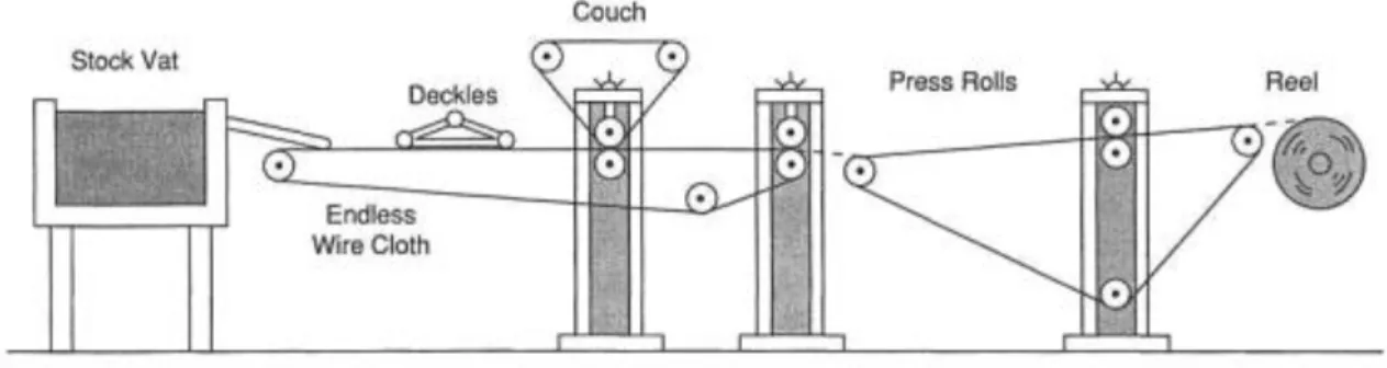
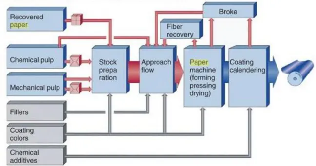
After the pulp refining the final stage focuses on the paper machine. The main task of the paper machine is to produce a high quality paper/board product that is required by the end user. Most paper machines consist of the following: a wire section where suspension is formed and the fibers are formed into a web by dewatering. A press section; which presses the water out of the web by mechanical pressure. The dryer section where the residual water is evaporated by heat. A sizing unit where the starch or pigments are transferred onto the web. A coating section where coating colour is applied to the web. The calender to finally smooth the paper/board surfaces. The end of the entire paper process is the paper web being reeled at the reeler at full width. Figure 4-1. shows an overview of the entire paper making process (Holik, 2013).
5. Types of Paper
There are over 400 types of paper; which is the main reason that the paper and paper board industry prefer to divide paper into broader categories based on the type of fiber used in the production process and the actual weight of the paper (Paper for Recycling: facts and figures, 2014):
Tissues
Uncoated groundwood Coated groundwood Coated wood-free paper Kraft wrapping or Bag
Cast-coated paper/ machine glaze/ MG kraft Specialty papers
Kraft Paperboards
Chipboard recycled paperboard Market pulp
6. Methods of paper collection
Local councils have been searching for years a system for wastepaper recovery from domestic households that are the most cost effective in order to stay in their allocated yearly budgets. The two most basic and most popular systems are the: - ‘Bring’ system – in which the households have already sorted recyclables for deposition in the allocated container at the recycling centres. This system involves all forms of recyclable material such as glass, used oil, and of course paper. Bridgewater Paper Mill, in the UK was the developer of the first example of this concept since the waste supplies a high proportion of the waste paper requirements that are needed to manufacture paper (Paper Online: recycling, 2014).
‘Collect’ system- Better known as the kerb-side collection since the recyclables are collected at the kerb-side of homes either mingled or separated in a box/bin system and then taken to the material recovery facility in a specialised vehicle.
6.1. Paper collection within the EU
The aim of the European Union is that paper collection must remain at the high levels that was reaching 70% in some of the countries and that it should increase in countries where it was below 60% in 2008 (Fischer & Werge, 2009). By 2015 the European Union wishes that 70% of all paper and paper-board products are recycled. In 2012 the EU made the world record of paper recycling with 71.2% (Paper for Recycling: facts and figures, 2014).
The EU has been trying to phase out the multi-material collection schemes (co-mingled collection) as a method of paper collection for recyclables for the paper industry. The reason being that co-mingled collection leads to contact with organic material, a higher share of unusable materials a refuse and is therefore less resource efficient and more costly in total. Countries that have co-mingled collection as the predominant collection method must make progress towards the targets of the separate collection set out by the European Union. The European Commission must approve of all programmes that the Member State wishes to implement since they have to ensure that the waste management does not endanger human health and is not harmful to the environment (CEPI, 2011).
For every Member State there are different national and regional collection systems for paper. According to the Waste Directive the collecting systems in place must be cost-effective and efficiently organized so that the necessary volumes and qualities of recovered paper can be obtained for recycling. In addition, the competent authorities must establish waste management plans to cover the whole territory of the Member State. In Europe, the largest amount of used paper is in fact supplied by waste management companies. This has helped to reduce the amount of paper going straight to the landfills and, also increased the availability of recovered paper to the paper mills.
All member states (with the exception of the United Kingdom and the Republic of Ireland) all follow the CEPI directive for the division of paper for recycling. This directive was established in October 2007 and has been in use ever since. The UK based list is known as the EN6433 and was used as a template for the CEPI (Lets recycle: Paper grades). The European Union brought in this directive for the division of paper so that every member state could be coherent and simplify the previous collection systems. Both CEPI and EN6433 can be found below in table 1-1 and table 1-2
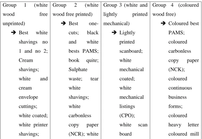
Table 1-1 UK Standard Waste Paper Groups EN643 (Lets recycle: Paper grades and EN6433, 2014). Group 1 (white wood free unprinted) Best white shavings no 1 and no 2; Cream shavings; white and cream envelope cuttings; Group 2 (white wood free printed)
Best one-cuts; black and white bests PAMS; book quite; Sulphate waste; tear white shavings; white
Group 3 (white and lightly printed mechanical) Lightly printed scanboard; white mechanical coated; white mechanical listings Group 4 (coloured wood free) Coloured best PAMS; coloured carbonless copy paper (NCK); coloured continuous business forms;
white soft tissue continuous business forms; white heavy letter; white listings no 1 and no 2 (CPO) (duplex); white unprinted new; woody one-cuts broke; coloured shavings; coloured tissue; mulitgrade sulphite bag water; white and light toned shavings Group 5 (heavily printed mechanical) Crushed news; green mechanical listings; heavily printed scanboard; mechanical book quire; news ad PAMS; over-issue news; over issue PAMS; telephone quire Group 6 (coloured crafts and manilas)
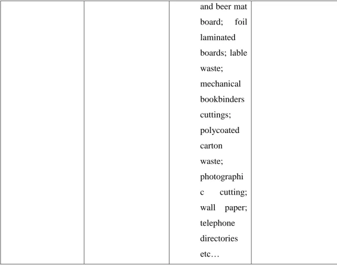
Buff and coloured tab cards, buff envelope cuttings; dark and light manilas; craft liner; multiply craft sacks; new brown crafts and old brown and coloured crafts Group 7 (new KLS) Double lined craft (DLK); new KLS cuttings Group 8 (container waste) Container waste (old KLS) Group 9 (mixed papers) Mixed papers Group 10 (coloured card) Coloured card Group 11 ( contaminated grades) Beer mats
and beer mat board; foil laminated boards; lable waste; mechanical bookbinders cuttings; polycoated carton waste; photographi c cutting; wall paper; telephone directories etc…
Table 1-2 CEPI Standard waste paper groups (Lets recycle: Paper grades and EN6433, 2014).
1.01
Mixed paper and board, sorted
1.02
Mixed paper and board, unsorted
1.03 Grey board
1.04
Supermarket
corrugated paper and board 1.05 Old corrugated containers 1.06 Unsold magazines 1.08 Mixed newspapers and magazines I 1.09 Mixed newspapers and magazines II
Sorted office paper Coloured letters Coloured wood-free magazines
Multi-printing
3.16
White wood-free coated paper without glue 3.18.01 White wood-free uncoated shavings 4.01 Unused corrugated kraft 4.02 Used corrugated kraft
6.2. Paper collection in China
China is the world’s largest importer of waste paper in order to fuel the strong demand of raw materials needed for its fast growing manufacturing sector (East Asia Infrastructure Department World Bank, 2005). It was hypothezied in 2004 by the Chinese Paper Authority that the prodution of paper and paperboard by the year 2009 would reach 86.4 million tonnes (Barnden, 2005) In 2009 China would overtake the United States as the world's largest producer of paper (Los Angeles Times, 2012).
However, even though China is the largest producer of paper and paper board material the recovery rate of these materials is extremely low. The amount of recycled paper pulp used in the mix was to be around 62% in 2011. That figured was estimated to increase from the 59% in 2009 (China Daily, 2013). Even now the recycling rate in China is around 40% much lower than the 70% in the EU. Chinese authorities have forecasted that this recovery rate will continue to grow to 52% by the year 2020 (WRAP, 2011). This means that China could satisfy its demands of paper with 72% of it from domestic sources instead of importing the waste from the EU and other countries (WRAP, 2011).
China has been working on the improvement of the local collection systems and by decreasing the amount of red-tape for the domestic paper-mills, easing the legislation concerning waste collection and, invested in the infrastructure for paper collection in cities. Still, the current rates of recycling are much lower than most countries, and is believed to be lower than stated. Many experts claim that much of the Chinese recycling system is a by-product of the import of low-cost secondary material from high-income countries who are exporting the material; and the popularity of incinerators. Often the owners of the incinerators discourage the message of waste reduction and recycling and they compete with recycling markets for combustibles such a paper, cardboard and wood since that are operated on a ‘take-or-pay’ agreement with the local authorities and guaranteed a
minimum waste delivery from the system (East Asia Infrastructure Department World Bank, 2005).
It is proven to be difficult to collect paper in China due to the large urban population and even with the recent changes the paper collection system is still inadequate. The Horizontal and vertical waste disposal units are most commonly used in China and the main method of recyclables in one that the EU has been trying to remove: the communal collection of multi-mingling. The main problem facing China with this method is that the bins fill extremely quickly and that people will throw any garbage in there. Recently there have been changes to the paper collection method such as households being given their own containers for recyclable items; increasing the amount of collection in urban area, and having separate communal for various organic-biodegradable materials on the streets. However, even with all the improvements that the Chinese have made to their paper collection system it still has a long struggle before being able to achieve the same levels as other high industrialized countries.
7. Processing Wastepaper
The purpose of waste paper processing is to create new stock for paper and paperboard products. The removal of non-fibrous material makes this possible. However, the quality of the end product cannot be matched with product that uses virgin pulp. The stock from wastepaper is not as reliable or of high quality like that of virgin fibers.
7.1.Wastepaper preparation and contaminant removal 7.1.1.Pulping
Wastepaper pulping is relatively new since the first hydrapulper was used in the USA in 1939 and in 1950 it became quite common to use in the pulping process.
Initially the pulper had a screen plate which had large perforation (8-20 mm diameter), the rotors had high peripheral speeds and defibering was the end result of hydraulic action instead of attrition. The introduction of more efficient rotors led to lower peripheral rotor speeds and smaller extraction perforations in the pulper (3-6 mm diameter). This system did cause problems since contaminants were left in the pulper, and broken down and heavy weight materials caused rapid wear of the rotor and tub. Another pulping strategy was adopted: the second pulper was added. The second pulper was a deflaker so no pulping was actually done in that pulper.
A side effect of the deflaker was that it also reduced the size of the contaminants, incidentally making the removal more difficult. This led to the use of another pulping system: the High- Consistency pulping. This system was developed in the mid 1970s and is now widely used in Europe and a similar system is used in Japan.
The pulper is the heart of the wastepaper processing plant and the main objective of the entire pulping process (including soaking towers and secondary pulpers) is to provide a completely defibered stock to subsequent cleaning stages. Remaining fiber flakes means that the cleaning efficiency is decreased and fiber losses are increased.
The following steps are included in the defibering process (Mc Kinney, 1995):
Separation of papers contained in wastepaper bales and water pretention into the paper.
Breakdown of inter-fiber bonds, to allow fiber separation.
Separation of fibers from contaminants such as adhesives, inks, laminanted materials etc., with minimal degradation of contaminants.
An energy input is required to achieve the defibering goal and it is this that provides the main difference between pulping options. The breakdown of contaminants is caused by rapid and high energy inputs. The speed of wetting is largely dependent on the condition of the pulper, paper type and the basin weight. The degree of sizing (waxing) of the paper is the most influential factor of the energy input needed in the pulping process. The reason being that the more sizing paper has the more energy is required in order to break the inter-fiber bonding.
7.1.2. Low-consistency pulping
The mechanical defibering forces in low-consistency pulping are high. The highest point for the force used in low consistency pulping is when the unpulped paper is wrapped around a static and rotating part, or in contact with a rotating part. When two ends of paper are caught in the stock flow the shear forces are created since the flows are moving in different directions. A substantial amount of energy is used in low-consistency pulping to move water so that no load power can be 60-80% of the total load. This in turn creates a vortex around the rotor and baffles are needed to improve the mixing. The mechanical forces between the rotor and the discharge screen plate are high, while the fiber-to-fiber interactions are low.
Stock is removed from the pulper through a screen plate with perforation continuously. Additional defibering and screening is provided with a secondary pulper. Before the low-consistency pulping was used for deinking, however, now it is rarely used for this purpose unless there is a soaking tower.
7.1.3. High-consistency pulping
High-consistency pulper are predominantly used due to their lower level of contaminant degradation and lower energy requirements.
With high-consistency pulping a helical rotor is used which is much larger than the low-consistency pulping rotor. Stock above 10-12% loses its fluidity and is quite viscous and the flow circulation patterns are very different from those in a low-consistency pulper; the vortex is not created and the pattern of circulation is top to bottom. The low rotor speed leads to a reduction of the cutting of plastic and other contaminants, but the shearing forces created are high since the velocity difference of the stock and the rotor is high. Mechanical forces are considered to be low and when no screen plate is placed the mechanical forces are extremely low. The stock crumbles and is pulled into the rotor, then intense defibering action is caused by the fiber-to-fiber rubbing.
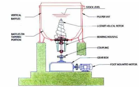
The pulper (Figure 7-1.) can be discharged either through a screen plate, or direct without any screen. When it is discharged through a screen the stock must be diluted before the actual discharge and the pulper vat has to be larger enough to hold the diluted stock. The contaminants are retained in the pulper and are flushed out and dewatered. The extracted water is returned to the pulper and reused. If the stock was removed from the pulper without screening it can be possible with or without dilution. If there was no dilution; there is an increased risk that gross contaminants will accumulate in the dump chest causes problem with pump blockages, etc. If the stock was diluted in the pulper or during discharge, gross contaminant removal is made using a detrashing tray. The contaminant are kept in the body of the screen and afterwards are washed and discharged at the end of the pulper dump cycle.
As previously stated the high-consistency pulping is the primarily used method of pulping. The benefits of high-consistency pulping include: reduced power consumption is up to 70% in comparison to low-consistency pulping; better contaminant removal, due to the reduction in the contaminant breakdown; and, a better rate of ink removal from the stock.
Figure 7-1. High consistency pulper (JMC machines, 2015)
The soaking towers is a concept that is still widely used in Asia, and the concept was popular in the 1950s and 1960s in Europe. The objective of the soaking towers is to defiber the flakes. The amount of time for the stock to be contained in a soaking tower can be up to 24 hours (in most cases it is 12-14 hours). The advantages of using a soaking tower is that there is an increased yield in comparison with other pulping systems, increased level of brightness, and the chemical and energy savings of 3-5% in comparison to other methods of pulping.
7.1.5. Screening and cleaning
The objective of screening and cleaning is to remove the non-fibrous contaminant and that useful fibers lost is a bare minimum. There is at the moment no better way of screening and cleaning, so there are many variations of the sequences. Normally, the equipment follows a pattern of consistency so for example low-consistency equipment is followed after high-consistency and vice-versa. This is to ensure the prevention of any possibility of stock consistency changes.
7.1.6. Screening
Throughout the centuries there was always some form of screening present during papermaking; but screening as it is known today was introduced in the late 1930s. In this time period the first pressure screens were developed. Around 1950 a non-contacting foil screen was developed; this allowed the face of the screen to be kept clean using a pressure pulse. In more recent times there has been further progression of the screen design and various baskets and rotors have been added to provide a variety of intensities and duration of pressure pulses. Also, due the changes of types of contaminants used in the papermaking process and the increased concentrations; the development of narrow-width slots have played an important role in the effectiveness of the contaminant removed.
Rotors on the screen allow improved selectivity of the stock since the fibers go through the screen whilst debris is rejected. The design of the rotor is primarily used to try and even out the load of stock in the screen basket. This is due to the fact that a high proportion of the accepted stock passes on to the screen basket.
In the early 1980s contoured screens were introduced. The reason behind this introduction was to increase the ability of stock fluidization because the contoured surface increases the turbulence of the stock flow. The increased turbulence reduce the blinding tendencies and the fractionation of the stock fibers.
The screen control systems is complex. The feed control is implemented via both pressure and consistency. The feed pressure has an effect on screen runnability (Mc Kinney, 1995). The consistency control is more import since screen efficiency and runnability can be affected (Mc Kinney, 1995) The control system is based on the difference between pressure of the feed and accepts; if the pressure goes over the set pressure limit the accept valve automatically closes. When the pressure decrease the accept valve opens and the process resumes as normal. A flow meter monitors any possible blockages by debris in the rejects valve.
The efficiency of screening is dependent on the following factors (Mc Kinney, 1995):
Screen basket design
Velocity through the screen basket opening
Stock consistency
Size and shape of contaminant
Rotor design
Power input and pressure differential between feed and accepts
Reject to inlet ratio for both flow and mass
Stock temperature
Of the above mentioned factors only a few can be controlled at a mill level. Moreover, leading to the importance of a control system; however, one should not underestimate the importance of the maintenance of the instrument sensors. This leads to the insight of possible repairs and replacements needed in the screen baskets and valves.
The reject disposal is the final stage of the screening system and also has the greatest impact on the overall efficiency. Previously a vibrating screen was the final treatment in the screening sequence; however, this was discontinued due to the fact that the vibrating screens actually created a heavily contaminated cycles, since it only rejected a small portion of the contaminants. At the moment cleaners may be used or centrifugal cleaners. What is important to observe with the final stage rejects is that if the reject is inefficient the contaminants will be recycled with the water used in the process.
One of the most common operating problems that occurs during the screening process is blinding. Blinding is when fiber or contaminants get caught up in one of the slot on the screen and causes a pile of material to form creating a mat, thus disrupting the flow of the stock. Blinding can be decreased if the fibers are longer than the screen capacity or if the screen has less slots in the baskets to increase the spacing. Control systems that test the debris level can also help with the reduction of blinding. The screen should be regularly examined and cleaned with an acid wash to prevent scale build up. In addition, an increase in blinding could be a sign of wear of the contours on the screen plate.
7.1.7. Centrifugal cleaning
The use of centrifugal force is for the separation of fibers and contaminants. Normally there are several stages, each stage varies in force to remove different types of contaminants. The principle of centrifugal cleaning is based on the specifics of gravity, basically meaning that contaminants can be removed from fiber, but only if they have a
High density, low-consistency cleaners – this is also known as the forward flow cleaner. This cleaner is used to remove small contaminants such as fine grit, sand, some inks, and coating.
Low density, low-consistency cleaners – also known as the reverse or through flow cleaners. This cleaner removes small contaminants for example wax, some plastics, some adhesives…
The first cleaner that is used after the pulping process is the high density cleaner. This cleaner has a larger diameter than a low-consistency cleaner because of the large pieces of debris that they need to filter out. Moreover, the high density cleaner has a larger outlet for the debris to prevent blockages. The cleaner rejects the debris into a reject box which needs to be emptied on a regular basis, otherwise rejects could build up in the cleaner and cause wear to the cleaner.
The low-consistency, high density cleaner was made in order to remove from the pulp systems substances like sand and grit. These types of cleaners have been extensively modified to be used in the paper recycling industry for the deinking process. At deinking mill there can be up to 4 stages of the cleaning process which involves the low-consistency, high-density cleaner. During the final stage, rejects are normally discharged into a water treatment system. The rejects during this phase of cleaning are also separated since the contaminants are of different dimensions and different consistencies.
Air can enter the cleaner as part of the stock and then migrates to the centre of the cleaner; providing stabilization of the column of air which is located at the axial centre line. The diameter of the airflow can in fact restrict the rejection flow, an often used compensation mechanism to prevent this is to increase the inlet pressure. However, this is useful only in a long-term situation. Whilst in a short-term variation this has been proven difficult especially with coated paper grade such as wood-free deinking. Vacuum systems are used to strip air from the rejects so that thee reject do not exit with the accepts. This helps with the stabilization of the air core.
Unlike other systems, the cleaners need regular maintenance to ensure that they are working at optimal capacity. High concentrations of grit can very quickly block a cleaner and if the cleaner is blocked it gets damaged very quickly. The areas most likely to be worn out are the lower cone and the rejects tip. A problem with the inspection of a cleaner is that the systems are unable to check for blockage during normal operation.
The final cleaner to be developed was the low-consistency, low density cleaner. In the late 1960s this type of cleaner was introduced so that lightweight particles could be removed from the stock. The consistency, low density cleaner is similar to low-consistency high density cleaner however the differences between the two is the diameters of the underflow and the overflow. In the low-consistency, low density the underflow is larger and the overflow is smaller. The amount of accepts is higher than the amount off feed given to the cleaner. Thus when working at maximum efficiency a requirement is to have high-pressure drop and high reject rates.
The control systems of the cleaners are normally manual; using throttles, valves showing the feedback and set pressures. Sometime in more modern mills there is a closed loop system to automatically control the accepts and the pressure in the cleaner.
The rejects made during the final stage are discharged, sometimes in a sewer. In this case there is no possibility of recycling unless the water is treated afterwards. Mostly, the rejects are pumped into a sludge blending tank.
7.1.8. Dispersion
Early units of dispersion were first used to deal with asphalt, waxed and bitumenised boards. Nowadays dispersion units are used for practically everything ranging from waste-based liner, deinking lines for tissue and newsprint. The reason the dispersion plays such a vital role was due to the emergency of polymer inks used in laser printers and copiers. The dispersion unit breaks down the large ink flake to a size that allows efficient removal. The dispersion process can also be used to replace the deinking process since the ink is dispersed so that there is no specky residue left; however, the ink is not removed from the stock.
Originally, the dispersion unit was used in order to ensure that the visible contaminant was reduced in size to improve the esthetic appearance of the sheet. In addition, it was used to disperse any large pieces of contaminant that could cause a problem later on down the operating line. However, as difficulties with the types of ink grew the emphasis of the main task of dispersion was switched to the reduction of the size
7.1.8. Types of dispersion and kneading units
Low speed units are known more commonly as kneaders. They vary with the amount of shafts that they have (single, double or triple shafts), and they are most often used in Asia.
The action that the kneader uses to manipulate the stock is a gentle shearing action, with twisting and compressing the fibers with no cutting. The forces that are generated in the kneader is very similar to the high-consistency pulper which generates inter-fiber interactions. Manipulating the temperature is possible to help with the dispersion of certain containments that is located in the stock; however, not a necessity.
Recently, there has been an increase of the tensile value located in the kneaders which is to do with the introduction of curl into chemical fibers. The amount of curl in the end result is dependent on the pulp yield of the stock, so the higher the value to pulp the less chance a curl will retain.
High speed units are also known as dispersers or dispergers. Unlike kneaders they only have single shafts with the addition of two plates: one is static while the other one is rotating at a high speed. The dispergers can vary in plate pattern, operating temperature and control systems. The temperature whilst in operation can vary from 50°C to 125°C the latter can only be achieved in a pressurized system.
The normal operation method for a disperger is due to the internal friction that is created in fiber mat between two plates. Like the kneader a cutting and crushing action of a fiber is avoided since the primary movements are grinding and flexing.
During the dispersion process the reduction of the brightness of the paper shows the effectiveness of the disperger since it is an indication of successful ink removal. The reduction of brightness is a direct consequence of the breakdown of contaminants that are located within the stock. In the case of high-speed dispersion tensile reduction is less than in comparison with low-speed kneading.
The left over contaminants that are not removed during the dispersion process are reduced in size so that they are no longer visible to the human eye. Operating using high temperatures and low disc gaps appear to be the best method of contaminant reduction. A process known as modelling can be involved during the dispersion. This is the prediction of dispersion effects. A model has be developed to predict freeness of the combination of temperature and the disc gap (Mc Kinney, 1995). So far, the best results produced for the residual speckiness and brightness are achieved after washing and flotation. The
effectiveness of deinking after high-temperature, high-speed dispersion implicates that is not because of the softening of the toner; however, due to the reduced viscosity that reduces the friction forces.
The advantages of the dispersion and kneading process is the paper production include (Mc Kinney, 1995):
Dispersion of visual contaminants;
Improved deinking;
They can eliminate the need for refining, since strength properties are enhanced;
Efficient use of bleaching chemicals can be achieved;
There is a reduction of microbiological activity (only in high temperature units);
Contaminants are reduced in size (high-speed units). The disadvantages are:
High operating costs, due to energy requirements;
Dependence on unit and conditions;
There is no contaminant removal. (Mc Kinney, 1995)
7.1.9. System design and applications
At the end of the 1980s high-speed dispersion units were placed at the end of the wastepaper processing line. This move substantially improved paper machine operation since it was successful in contaminant dispersion and maintained less deposition problems with stickies. The reduction/elimination of refining aided with the increased cost of paper; however, the brightness fell since the dispersion of the ink speck. Using dispersion allowed a form of protection of the paper machine; however, this objective has become secondary since now it is viewed as an integral component of the deinking process. Especially so in the wood-free deinking mills which can be exposed to substances such as laser printed and xerographic toners.
pressure sensitive adhesives. Nevertheless, this type of unit has proven to be popular in Asia, which has also adjusted the process into 2 stages in order to allow the recycling of laser and xerographic papers into high-quality printing and writing paper. (Mc Kinney, 1995)
7.2. Deinking
Deinking is considering to be the most complex part of the wastepaper recycling processing. There are two complementary parts of the deinking process: the washing and the flotation. All the way until the 1920s these methods were considered a competitive systems with mills often choosing between one or the other. Now there is widespread knowledge that the best result are achieved when the both are used, since wash deinking is not effective for the removal of large specks (+20 mm), while on the other hand using flotation in the removal of small specks (-20 mm) is not effective. However, small particles can be removed by flotation, if they are agglomerated to form large particles (Mc Kinney, 1995)
Ink is broken down when the waste paper has been repulped, thus causing particles with a wide range of sizes to be suspended into the pulping liquid. The entire deinking process is to separate this particles from the fibers with minimal loss of useful fibers. A link has been established between the brightness and the ink content. The size distribution of the ink particles has to be weighing towards small and medium in order for this to have any validity.
While the wastepaper is being pulped, the fibers are simultaneously wetted and ink particles are produced. At the surface of the fiber a layer of water is bond strongly and becomes contaminated with ink. In the more irregular surfaces, such as the fibrils, the water may extend just enough to trap some small ink particles.
Complete removal does not occur during the flotation or wash deinking irrespective of the number of stages and at the moment there is not explanation to why this occurs. In addition, to this mystery there are many phenomena that are unknown in deinking, for example, some fibers become heavily coated in ink particles and it is not because of their fiber type and their affinity to certain inks particles are not explainable. Also, it there is no explanation to the role which surface chemistry plays in the removal of ink.
7.2.1. Wash deinking
The simplest way to describe the process of wash deinking is: the ink is broken up on pulping and some of these particles are removed during the wash stages with a washer filtrate. Even without the use of chemicals this can be quite efficient. The method used during the wash deinking is a thickening process caused by mechanical separation: ink particles are separated from the fibers by a synthetic wire, most commonly made from plastic. The ink specks need to roughly be the size of the mesh of the wire, which is based on the formula of the proportion of amount water removed in the thickening phase.
Efficiency of wash deinking is established via the speed of the formation of a mat and the thickness: basis weight of the mat. This, however, can only be seen in the next portion of the dewatering cycle. Washing often causes an increase of the freeness of particles since the strength properties tear during the process. If all the solids are removed then a general improvement of strength properties occurs; however, if all the fines which are considered ‘active’ meaning they contribute to the inter-fiber bonding then the burst particles will fall. Making the washing ineffective.
A variety of factors can influence the efficiency of washing: the pH, temperature, and the treatment used prior to washing normally during pulping.
7.2.2. Pulping conditions
The chemical concentrations used during pulping have a considerable impact on the washing efficiency, since it directly influences the size of the ink particles. A high pH is probably effective in the breakdown of ink and creating an increased degree of stability to the particles (Mc Kinney, 1995). The pulping consistency is also important, since the higher the consistency the smaller the specks are produced leading to a lower brightness. 7.2.3. Wash conditions
In the counter-current systems the nature of the individual solids in the filtrate changes throughout the stages. The actual concentration of the solids does not change drastically between each wash stage, but the nature of the solids in the back water does. So this is the reason why counter-current washing is effective in limiting the fiber loss but not as effective in the removal of ink. Actually, during the process some ink that is removed is trapped by the filter mat and increases the overall retention of ink.
7.2.4. Equipment used in wash deinking
Practically, any type of thickening device can be used to function as a washing unit. However, there are exceptions such as the two stage thickener, which first passes filtrate back through the filter mat this does not function as a wash unit. If backwater from the washing stage is reused without the removal of ink and solids, washing will not be effective. As mentioned previously there is a wide variety of devices that are used as a washers, including screw presses, gravity deckers, sidehill screens and belt washers.
Screw presses have been used for many years in the deinking process, in the role of wash units and thickeners. There is a pithed screw rotating in a fixed screen barrel. The pitch of the screw can be varied and also, its length, speed and perforation size. The extracted water drains through the perforations. These perforations are considered effective in ash removal; however, are associated with high losses of fiber and fines. The fiber losses can be reduced with the use of a fiber recovery stage before the backwater clarification and/or discharge. Ash reduction within the screw press is influenced by the stock freeness, pH, temperature and the overall condition of the screw press. The washing effect is increased by high freeness, pH and temperature. The efficiency of the screw press falls when the perforations are not kept clean. In this situation, scale builds up and closes the perforations. The solution to this problem is simply an acid wash.
Drum washers (gravity deckers) are a less popular method, due to the introduction of belt washers. Generally, they are plastic or mesh covered cylinders which rotate in a vat; water passes through the mesh, forms a mat of the washed stock on the mesh and the filtrate or backwater is rolled off. The mesh is regularly cleaned by showers.
The factors which influence the efficiency of the deckers are (Mc Kinney, 1995):
Stock freeness;
Head difference between the stock in the vat and the filtrate;
Water system and quality;
Mesh size and cleanliness;
Inlet consistency
A good seal between the vat and the filtrate is hard to maintain, but if it is not maintained the fiber loss increases. High-speed operation which is used to improve washing efficiency may lead to stress-cracks in the cylinder body.
Disc and vacuum filters are used as thickeners. The thickeners operate in a closed loop cycle and there is no water clarification. In most cases this involve a two stage cycle where a cloudy filtrate is created when the mat builds up on the mat of the disc segment. Then it is collected after the mat is formed. The cloudy filtrate can be recycled, or it can be used as a consistency dilution of water. Vacuum assistance may be provided to the dewatering process, by use of vacuum pump or barometric legs.
7.2.5. Flotation deinking
Flotation is used to achieve better brightness results. The first cells used during the deinking process were similar to mineral ore flotation, which are still used today. Initially the Denver cell unit was used in the flotation process; however, there are been many changes in the flotation deinking process in the period of 1972-1993 Even though, there have been changes to the appearance of the unit, it did not bring an increase of the performance. What has been reported is the changes which resulted in lower energy consumption in comparison to older modules.
The basis of flotation is that ink particles are more hydrophobic than paper fiber, with the exception of water-based inks which are in fact hydrophilic. Ink removal effectiveness of flotation deinking range from 50-70% (Mc Kinney, 1995).
In order of ink removal to occur the following must happen:
Ink particles need to be free; which means that they are not allowed to be bound to fiber surfaces or trapped in the filbrillar areas, or bound in the water.
Each individual step is dependent on a variety of chemical conditions and mechanisms, which are in some cases inter-dependent. The success of flotation deinking is affected by many factors which include:
Stock consistency. The consistency increases as the drag on the air/ink complex increases, because the fibers form a network. This lead to a reduction in the rise of velocity and collisions with fibers can possibly dislodge ink particles. Lower consistency is better for flotation effectiveness.
Stock temperature and pH. When temperature increases the effectiveness of flotation decreases. When the pH increases above 9 that leads directly to a drop in the efficiency of flotation. However, in both cases it does regards the chemical compounds that are located in the ink.
8.Water and waste water treatment in recycling mills
Water pollution from waste paper recycling is a large scale problem because of the fact that paper making consumes vast amounts of water. Standards concerning the discharge of water have risen in recent years meaning that the water returned should be usable for almost all purposes. Paper mills are trying ways to become zero liquid effluent, that is, that they are trying to close the water based paper mill system.
During the 1980s the Kimberly Clark Corporation created a pilot paper mill that used dry processing instead of the traditional water based. However, this was not successful because the paper produced was sub-quality in comparison to the wet processing. The greatest problem surrounding dry processing is fiber separation without any fiber damage; this is because of the hydrogen bonds in the paper when dry.
In a dry state the cellulose fibers that the paper is made out of are in the compresses state. Wetting the fiber weakens the compressive forces. Hydrogen bond between the cellulose fibers are replaced with water molecules and thus, making separation of wet fibers much easier. However, during dry separation there is fiber damage because the fibers are broken away instead of being pulled away from the neighboring and overlapping fibers in the paper.
Whilst waste water is not of much concern during the process of paper making, during the production of recycled paper there is reason to be concerned. Mainly because, in recycled paper there are many more particles other than the virgin fibers such as inks, glues, grit and etc. In order to prevent the pollution the particles need to be removed before the water is discharged from the paper mill. Which is why there is a need for the treatment of waste water.
8.1. Freshwater use in recycling
The cost of the use of a single freshwater pass through a mill would be extremely expensive since it requires a very high consumption of water and with consequent high
Type of wastepaper being recycled;
Product being produced;
Integration of recycling process with paper or board mill;
Water availability and cost;
Water losses in product, sludge, evaporation, etc;
Sophistication of water clarification systems. (McKinney, 1995)
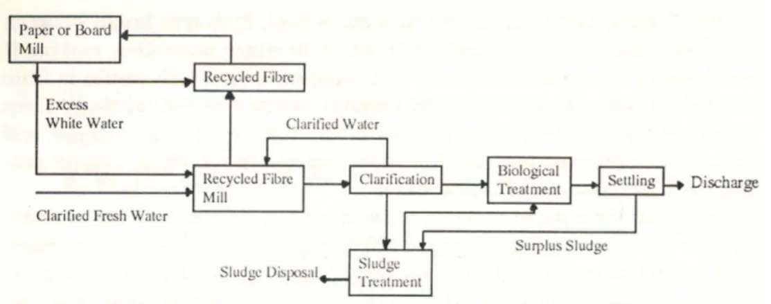
The use of freshwater is normally limited to the boiler makeup, cooling, sealing and some chemical makeup uses. In figure 8-1 a simple freshwater circuit for a recycling mill is illustrated.
Figure 8-1. Fresh water circuit diagram (Mc Kinney, 1995)
The treatment of the boiler feed water needs to be at a high standard and is provided by a potable water supply. Other mill water needs are provided by fresh water from various sources i.e. surface water, well water, bore water.
In order to minimize freshwater use, the freshwater should be collected and reused by diverting the flow to the freshwater tank. When it is not possible for the reuse of a freshwater duty for example, when the temperature is too high; it should be applied to the next highest quality demand. By using a cascade system to the cleanest duty to the lowest quality allows freshwater use to be minimized. It is possible to collect and filter the sealing and cooling water and reuse it in the recycling process. The conductivity measurements can warn of any potential leaking seals due to the contamination levels.
8.1.1. Freshwater treatment
The raw water-quality is the main factor which suggests the degree of treatment required and the end use of the water. It can be a possibility that the fresh water can be used without any treatment, such as, well water. Depending on the function of the
freshwater there can be different way of treating for example is colour removal was necessary an aluminium sulphate and a secondary polyelectrolyte may be needed; or sometimes, filtration and sterilization is enough.
8.2. Effluent loads
The content of the effluent stream from a recycling mills are a mixture of fibers; fibre fines; crill, ink particles and, inorganic and organic materials. The percentage of the particles vary according to the type of wastepaper being recycled.
Because of the substance of the various fibers being or an either inorganic or organic deposition the importance of the effluent COD: BOD (chemical oxygen demand: biological oxygen demand) is necessary to explain. If these ratios are low typically within the range of 4:1 this indicates that an effluent is easy to treat biologically. The higher difference between ratios indicates more problems with treating the effluent stream.
During individual processing stages certain organic loads are created; for example; bleaching with hydrogen peroxide dissolves natural resin and fatty acids. Because of this treatment it is likely to see resin and fatty acids, or chlorine residues in the mill effluents. Whilst toxic, the by products are easy to remove from the stream and thus posing no threat as an environmental hazards or treatment difficulty.
8.3. Effluent Treatment Standards
If the recycled paper and board mill effluents are left untreated they can have a substantial impact on the water ways in the discharge area. The immediate effects are caused by the suspended solids i.e. calcium carbonate, clay and organic fibers. The previously mentioned materials settle quickly not only near the discharge site but also in the area of the stream flow. Sludge starts to form and kills the plants and fish. The secondary problem caused due to the sludge is oxygen depletion. The organic components of the sludge are broken down anaerobically and strip the water of oxygen. Bubbles of gas are released and rise to the surface so that scum forms, which is then followed by a foul
demand). All type of mills in the paper industry have been under scrutiny to prevent acute and chronic toxicities, and the bioaccumulation of potentially toxic substances for fish. Most mills, in accordance to regulatory standards, must have some form of clarification and biological treatment, or discharge the untreated/partially treated effluent to the sewer. However, due to even more stringent standards an installation of a tertiary treatment will be probably implemented in the future.
8.4. Physiochemical Treatment process- Waste Water Clarification
As previously mentioned, waste water streams carry the materials that were removed during the wastepaper processing. If the water is to be reused it must be removed, otherwise, the concentration of chemicals will build up since the water is re-looped during every production of waste paper recycling. This is where water clarification plays an important role in the recycling operation, especially in deinking. In some deinking systems there are multiple stages of water loops used. In these stages different pH conditions apply. The segregation of the water loops provides a minimal recontamination of fibers which are dissolved or suspended. Various loops off acid and alkali are used to remove the organic components.
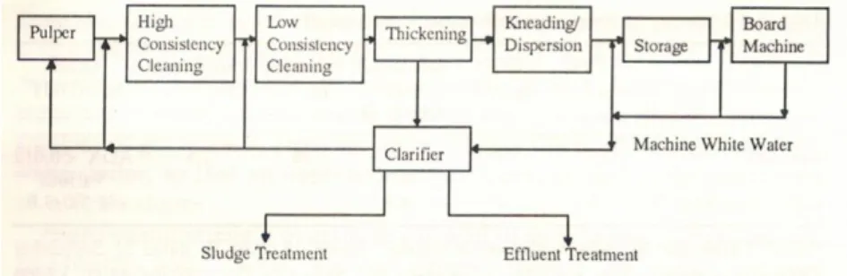
Packaging wastepaper lines require a lower quality demand so most often have a single water loop (Figure 8-2.). Few recycling mills have managed to reach the level of zero effluent discharge. In systems where complete closure is available, a series of complex water treatment systems are used, which include; spill collection, use of cooling towers, and closed loop sealing water. This is designed for optimal removal of COD.
Figure 8-2. Water loop, packing grade schematic (Mc Kinney, 1995)
The open water system is preferred, because of the various problems that are encountered with closed loop systems. The problems that are found in closed systems include: