AN INVESTIGATION INTO THE RESISTANCE COMPONENTS OF CONVERTING A TRADITIONAL MONOHULL FISHING VESSEL INTO
CATAMARAN FORM
Samuel1*, M. Iqbal1, I.K.A.P. Utama2
1
Department of Naval Architecture, Faculty of Engineering, University of Diponegoro, Semarang 50275, Indonesia
2
Department of Naval Architecture and Shipbuilding Engineering, Faculty of Marine Technology, Institut Teknologi Sepuluh Nopember (ITS), Surabaya 60111, Indonesia
(Received: March 2015 / Revised: June 2015 / Accepted: July 2015)
ABSTRACT
Resistance or drag is one of the most important factors in ship design, in particular in connection with the development of more efficient and environmentally friendly vessels. The shape of the hull under water will affect the fluid flow characteristics around the ship, hence causing the resistance to increase or decrease. If the resistance increases, the size of main engine and subsequently, the fuel consumption increases accordingly and this is not often anticipated by ship designers and operators. The use of a catamaran for passenger carriers is well known and its application for fishing vessels has received serious attention in the last few years, due to its advantages to produce wider deck area and smaller size of engine at the same displacement as the monohulls. The conversion of monohull fishing vessels in Cilacap the waters into a catamaran hull is an interesting topic in association with the development of better fishing vessels in this region. The resistance investigation of the conversion vessel was carried out by Computational Fluid Dynamics (CFD) approach and this is combined with classical slender body theory. In terms of mathematical calculation, the results between CFD and the combination of empirical formulas and slender body theory shows such a good agreement and the difference between the two is less than 5%. In terms of naval architecture, the results showed that the modification of a monohull vessel into a catamaran can increase the payload capacity up to two times. Conversely, this causes the resistance to increase about almost four times and this is certainly unpopular for the fishermen.
Keywords: Catamaran; CFD; Monohull; Resistance; Slender body
1. INTRODUCTION
Successful research and development of catamarans for passenger carriers have inspired Setyawan et al. (2010) to extend their application into fishing vessels. It was found out that the total resistance of a catamaran is smaller than that of a monohull with similar displacement. This power efficiency will, in turn, save the use of fuel energy. Armstrong (2003) focused his efforts on identifying the different resistance components; in particular, by means of double model tests in a wind tunnel. It has been shown that there is a significant interference of a purely viscous nature between hulls in close proximity.
The calculation of power required by the catamarans needs an investigation into the resistance
*Correspo di g author’s e ail: [email protected], Tel. +62-24-76480784, Fax. + 62-24-76480784
characteristics entirely in order to obtain the most effective resistance by ship design (Molland, 2008; Turner & Taplin, 1968). The investigation of the effects of the separation distance on the resistance components was also carried out by Millward (1992); and Molland et al. (2004), by means of both experimental tests and theoretical approaches. A considerable amount of research has been carried out to determine the resistance interference effects of demihulls of catamarans in proximity of one hull adjacent to the other, including experimental and theoretical work from Sahoo et al. (2007) and Muller-Graf et al. (2002). But, all of these investigations have focused on the effects of various lateral separations. A lot of work on the catamaran resistance has been carried out worldwide. Insel and Molland (1992) introduced the use of experimental model test of NPL series model and compared with thin ship theory method to derive the components of catamaran resistance and produced the popular formulation for the derivation of catamaran resistance. Utama (1999) applied CFD approach using CFXTM code to derive the viscous resistance component of the catamaran and found out such good agreement with an experimental test model in the order of a margin of error of less than 5%. Moraes et al. (2004) used the Shipflow code, together with Slender Body Theory and discovered that the separation to length (S/L) ratio above 0.6 does not have a significant effect on the wave resistance.
Almost all of the ship types for the fisheries sector in Indonesia are of single hull or monohull. Due to the high growth of fisheries activity in the coastal areas, as a consequence, the needs for better ship design increases. In line with the Government's program to maximize the potential of fisheries with the fishing vessel development in all regions in Indonesia, the development of catamaran fishing boats was carried out. The same idea was applied into the conversion of monohull fishing vessels into catamaran form of fishing vessels. The design of fishing vessels in the Cilacap region, which is a traditional one, cannot be ignored because it is a heritage from the ship craftsmen’s ancestors. In this case, the monohull design is modified in such a way and converted into the catamaran form. The investigation was focused on the resistance components derivation using CFD Tdyn code and validated using the slender body method. The calculation of ship resistance using Tdyn has been carried out by Iqbal and Utama (2014) to estimate the trimaran ship resistance in shallow waters. In the case of wave resistance derivation, recent work by Jamaluddin et al. (2012) was considered.
2. METHODOLOGY
In order to increase the payload capacity and area of main decks, traditional fishermen in Cilacap have modified the vessel hull form which initially is a monohull into a catamaran hull without considering the increase of resistance. Therefore, an investigation was conducted in order to evaluate the increase of total resistance caused by the conversion. Main dimensions and hull form of the monohull were obtained based on the results of field or direct measurement. Ship resistance calculation was calculated using 1:10 scale model of the ship.
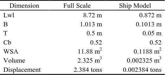
Table 1 Main dimension of fishing vessel monohull
Dimension Full Scale Ship Model
Lwl 8.72 m 0.872 m
B 1.013 m 0.1013 m
T 0.5 m 0.05 m
Cb 0.52 0.52
WSA 11.88 m2 0.1188 m2
Volume 2.325 m3 0.002325 m3
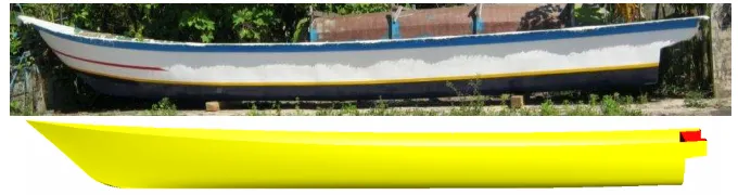
The measurement results of main dimensions and ship models are presented in Table 1 and the photograph together with a 3D model of the monohull vessel are shown in Figure 1.
Figure 1 Hull Form and 3D model of monohull vessel
The monohull vessel was modified into a catamaran form with the ratio of space between the hull and the ship (S/L) as 0.2. Figure 2 show an increased payload capacity up to 4.768 tons. The draught of catamaran vessel is made the same as that of the monohull vessel. The speeds used in this study are between 0.516 m/s and 2.054 m/s.
Table 2 Speeds of model and vessel
Fr V model V full scale m/s knots m/s knots 0.18 0.516 1.00 1.63 3.17 0.26 0.769 1.49 2.43 4.73 0.35 1.022 1.99 3.23 6.28 0.44 1.294 2.52 4.09 7.96 0.53 1.548 3.01 4.89 9.51 0.62 1.801 3.50 5.69 11.07 0.70 2.054 3.99 6.49 12.62
Figure 2 Hull form and 3D model of catamaran vessel
al., 2010; Broglia et al., 2011; Tezdogan et al., 2015). Bhushan et al. (2009) The CFD simulation performed resistance and powering computations of the full-scale self-propelled Athena ship free to sink and trim use both smooth and rough wall functions. Then, Wilson et al. (2008) and Paik et al. (2009) performed CFD simulations to predict the pitch and heave transfer functions of the S-175 ship in regular head waves.
The incompressible Navier-Stokes-Equations in a given three-dimensional domain and time interval (0, t) can be written as (Tdyn, 2014a):
(1)
where u = u(x, t) denotes the velocity vector, p = p(x, t) the pressure field, the density, the dynamic viscosity of the fluid and f the volumetric acceleration. The spatial discretization of the Navier-Stokes equations has been conducted by means of the finite element method, while for time discretization, an iterative algorithm that can be considered as an implicit two-step "Fractional Step Method" has been used (Kleinstreuer, 1997). Using the standard Galerkin method to discretize the incompressible Navier-Stokes equations leads to numerical instabilities (García et al., 1998).
The two-equation model for turbulent flows with integration to the wall is expressed in terms of a k-ω model formulation. The k-ω shear-stress-transport (SST) model combines several desirable elements of standard k-ε and k-ω models. The two major features of this model are a zonal weighting of model coefficients and a limitation on the growth of the eddy viscosity in rapidly strained flows. The zonal modeling uses the k-ω model near solid walls and a standard k-ε model near boundary layer edges and in free-shear layers. This switching is achieved with a blending function of the model coefficients. The SST model also modifies the eddy viscosity prediction, improving the prediction of flows with strong adverse pressure gradients and separation. The SST model has also been used in many other studies, such as (Menter, 1994; Menter, 1993; Swennberg, 2000; Bardina et al., 1997).
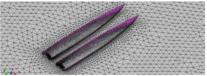
The computational domain is discretized by means of an unstructured surface mesh grid. The mesh around the catamaran consists of about 977012 million cells distributed is presented in Figure 3. The recommended value of the Time Increment for free surface analysis is dt<0.05L/V or dt<h/V, being L a ship length, V the mean velocity, and h an average of the element size (Tdyn, 2014b).
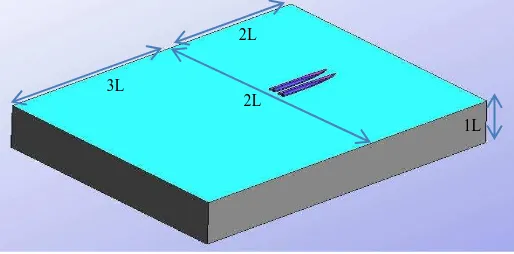
The locations of the boundaries are illustrated in Figure 4, which gives 3D views of the domain. It is worth mentioning that throughout all the cases, in order to prevent wave reflection from the walls, the empirical formula used is based on a formula contained in Jamaluddin et al. (2012) which is a modification of the Molland et al. (1996) method in which this formula is used to calculate the viscous resistance of catamarans and wave interference.
Figure 4 The dimensions of the computational domain for simulation resistance (L; Length over All)
The formula used to calculate the catamarans resistance is contained in Equations 2 to 9, where Ct is the Coefficient of total resistance, Cf is the Coefficient of friction resistance obtained by the skin friction formula ITTC-57, Cw is the Coefficient of wave resistance, Cw is the Wave resistance interference factor and (1+βk) is the viscous form factor.
Ct = (1+βk)Cf + τCw (2)
The empirical formula to calculate (1+βk) is presented in Equation 3 and the empirical formula to calculate (τ) is presented in Equations 3 to 9. Details of the derivation of those formulas are given in (Jamaluddin et al., 2012).
(1+βk) = 3.03 (L/Vol1/3)-0.40 + 0.016(S/L)-0.65 (3)
= 0.068(S/L)-1.38 , at Fr = 0.19 (4)
τ = 0.359(S/L)-0.87 , at Fr = 0.28 (5)
τ = 0.574(S/L)-0.33 , at Fr = 0.37 (6)
τ = 0.790(S/L)-0.14 , at Fr = 0.47 (7)
τ = 0.504(S/L)-0.31 , at Fr = 0.56 (8)
τ = 0.501(S/L)-0.18 , at Fr = 0.65 (9)
The formula that Molland et al. (1996) and Jamaluddin et al. (2012) generated is based on the experimental study. The parameter model that is to be tested by both of them is compared to the parameter model in this study for validation. The first parameter is the ratio of length to width of a demihull vessel or L/B. The second parameter is the ratio of the width of the demihull ship to draught or B/T. The third parameter is the value of Block Coefficient or Cb. The fourth parameter is the value of the ratio between the length of the vessel to the cube root of the volume of the demihull. Table 3 shows that the comparison of all parameters in this study is still in the range of parameters defined by Molland et al. (1996) and Jamaluddin et al. (2012). Then for CFD validation only use a formula is generated from their experimental testing. So the experimental test is not necessary.
3L
2L
Table 3 Comparison of parameters research
Parameters This research (Molland et al. 1996) (Jamaluddin et al. 2012)
L/B 8.61 6 to 12 11.15 to 21.25
B/T 2.03 1 to 3 0.53 to 1.58
Cb 0.52 0.33 to 0.45 0.547 to 0.616
L/Voll/3 6.58 6 to 9 7.17 to 7.30
3. RESULTS AND DISCUSSION 3.1. Total Resistance of Monohull
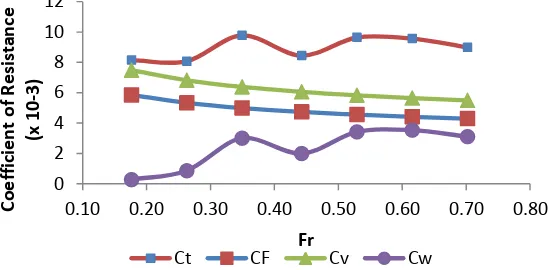
Total resistance components consist of viscous resistance and wave resistance. The viscous resistance is obtained from frictional resistance multiplied by a form factor (1+k). The form factor is calculated using the Holtrop formula to give the value of (1+k) = 1.279. The estimation of frictional resistance is calculated using the (ITTC, 2002) ITTC 1957 correlation-line and the wave resistance was calculated using the Slender Body Methods. The results of the resistance coefficient calculation for the monohull vessel are presented in Figure 5. Based on Figure 5, it can be seen that the component of viscous resistance has a larger composition than wave resistance. The reason for this is attributed to the slender hull form of a Cilacap traditional vessel, which is useful to minimize wave resistance.
Figure 5 Drag coefficients of the monohull vessel
3.2. Total Resistance of Catamaran
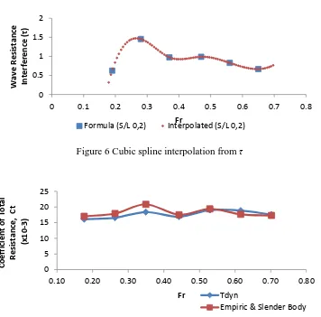
The components of total resistance of a catamaran consist of viscous resistance and wave resistance together with their resistance interactions (Gillmer & Johnson, 1982). The viscous resistance is obtained from frictional resistance multiplied by a form factor. Based on Equation 2, the form factor value is 1.443. The calculation of viscous resistance of a catamaran is carried out using the frictional resistance of a monohull multiplied by a form factor. The calculation of wave resistance of a catamaran is done using the wave resistance of a monohull multiplied by wave resistance interference. Frictional and wave resistance of a monohull are presented in Figure 5. Wave resistance interference is calculated using Equations 3 to 8. In this study, the method used to interpolate the wave interference (τ) at the desired speed is the cubic spline interpolation method. The results of interpolation can be seen in Figure 6. In Figure 6, it can be seen that the wave resistance interference between the two hulls can increase the wave resistance when the wave interference value is greater than 1. This condition occurs at Fr between 0.20 and 0.37. The favorable interference, which reduces the wave resistance, occurs when the value of wave resistance interference is below 1 and this condition occurs at Fr above
0.10 0.20 0.30 0.40 0.50 0.60 0.70 0.80 0
2 4 6 8 10 12
Fr
C
o
e
ff
ic
ie
n
t
o
f
R
e
si
st
a
n
ce
(x
1
0
-3
)
0.47. The total resistance of a catamaran can be calculated using Equation 10 and the value of Ct is multiplied by 2 because the combined value of Cf and Cw is the value of a monohull vessel. Where, Rt is total resistance, ρ is density of seawater, v is speed of vessel, WSA is wetted surface area of a catamaran, and Ct is the total drag coefficient of a catamaran.
Rt= 0.5ρv2WSACt (10)
Figure 6 Cubic spline interpolation from τ
Figure 7 Comparison of coefficient of total resistance
Therefore, in order to obtain Ct of a catamaran, the Ct of a monohull is multiplied by 2 and then added to the viscous and wave resistance interference between the hulls. Besides using a combination of empirical calculations and the slender body, the calculation of vessel resistance in this study was carried out using CFD methods together with the Tdyn code. The results of catamaran resistance using CFD method is shown in Figure 7. The total drag coefficient comparison between the combination of empirical formula and slender body with CFD method was presented in Figure 7. Based on Figure 7, it is known that the average difference between the empirical calculation and CFD is relatively small, which is about 5%.
3.3. Comparison Total Resistance of a Monohull and a Catamaran
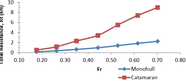
The comparison of resistance between a monohull vessel and a catamaran was presented in Figure 8. Resistance of a catamaran used is based on the combination methods of empirical formulas and slender body. The payload of a monohull with a displacement of 2,384 tons (Fr of 0.70) has a total drag of 2,306 N, whilst the catamaran mode with a displacement of 4,768 tons has a total drag of 8,807 N. It means that, the catamaran form has a payload twice as much as the payload of a monohull vessel. However, in terms of ship resistance and based on Figure 8,
0 0.1 0.2 0.3 0.4 0.5 0.6 0.7 0.8 0 0.5 1 1.5 2 Fr W a v e R e si st a n ce In te rf e re n ce ( τ)
Formula (S/L 0,2) Interpolated (S/L 0,2)
0.10 0.20 0.30 0.40 0.50 0.60 0.70 0.80 0 5 10 15 20 25 Fr C o e ff ic ie n t o f T o ta l R e si st a n ce , C t ( x 1 0 -3 ) Tdyn
the resistance of the catamaran increases almost four times (i.e. 284%). Consequently, the engine power and fuel consumption of a catamaran will increase significantly. This is certainly bad news for the fishermen in Cilacap.
Figure 8 Comparison of monohull and catamaran resistance
The positive impact of the modification of a monohull vessel into a catamaran vessel is the increase of payload up to double. Moreover, the other advantages of catamarans compared with monohull vessels is the wider deck area provided by the catamaran as well as more comfortable level of stability and safety (Seif & Amini, 2004).
4. CONCLUSION
The current research clearly demonstrates the effective use of CFD together with the use of CFD code (Tdyn) in predicting the resistance of catamaran hull type developed in Cilacap. The results of CFD are in good agreement with well-known empirical formulas used by commercial design software (Maxsurf) and slender body theory of the order of magnitude of error of less than 5%.
Furthermore, the modification of a monohull vessel into a catamaran type increases the payload capacity almost double. However, in contrary this causes aproximately a quadruple increase in ship resistance. This fact is surely bad news to the fishermen and further research is strongly recommended.
5. ACKNOWLEDGEMENT
The authors wished to thank the Ministry of Education and Culture of the Republic of Indonesia for the funding support of the research number DIPA-023.04.2.189815/201 December 5th 2013.
6. REFERENCES
Armstrong, T., 2003. The Effect of Demihull Separation on the Frictional Resistance of Catamarans. In: 7th International Conference on Fast and Sea Transportation. Ischia, Italy: FAST 2003
Bardina, J.E., Huang, P.G., Coakley, T.J., 1997. Turbulence Modeling Validation, Testing, and Development, NASA Technical Memorandum 110446. Moffett Field, California
Bhushan, S., et al., 2009. Model- and Full-scale URANS Simulations of Athena Resistance, Powering, Seakeeping, and 5415 Maneuvering. Journal of Ship Research, Volume 53(4), pp. 179–198
Broglia, R., Zaghi, S., Mascio, A.Di., 2009. Analysis of the Hydrodynamic Performances of High-speed Catamarans by Viscous Flow Solver. In: Isope. pp. 740–747
0.10 0.20 0.30 0.40 0.50 0.60 0.70 0.80 0
2 4 6 8 10
Fr
T
o
ta
l
R
e
si
st
a
n
ce
,
R
t
(k
N
)
Monohull
Broglia, R., Zaghi, S., Mascio, A.Di., 2011. Numerical Simulation of Interference Effects for a High-speed Catamaran. Journal of Marine Science and Technology, Volume 16(3), pp. 254–269
García, J., et al., 1998. A Stabilized Numerical Method for Analysis of Ship Hydrodynamics. In: Proceedings Eccomas Conference on CFD. Athens: John Willey
Gillmer, T., Johnson, B., 1982. Introduction to Naval Architecture, US Naval Institute, Annapolis, MD
Insel, M., Molland, A.F., 1992. An Investigation into the Resistance Components of High Speed Displacement Catamarans. Trans RINA, 134
Iqbal, M., Utama, I.K.A.., 2014. An Investigation into the Effect of Water Depth on the Resistance Components of Trimaran Configuration. In: Proceedings of the 9th International Conference on Marine Technology. Surabaya
ITTC, 2002. Report of the Resistance Committee. In: Proceedings of the 23rd International Towing Tank Conference. Venice, Italy: INSEAN
Jamaluddin, A., et al., 2012. Experimental and Numerical Study of the Resistance Component Interactions of Catamarans. In: Proceedings of the Institution of Mechanical Engineers, Part M: Journal of Engineering for the Maritime Environment, Volume 227(1), pp. 51–60 Kleinstreuer, C., 1997. Engineering Fluid Dynamics, An Interdisciplinary Systems Approach,
Cambridge, UK: Cambridge University Press
Menter, F.R., 1993. Zonal Two Equation k-ω Turbulence Models for Flows. AIAA Journal, pp. 93–2906
Menter, F.R., 1994. Two-equation Eddy-Viscosity Turbulence Models for Engineering Applications. AIAA Journal, Volume 32(8), pp. 1598–1605
Millward, A., 1992. The Effect of Hull Separation and Restricted Water Depth on Catamaran Resistance. Transactions of Royal Institute of Naval Architects, pp. 341–349
Molland, A., et al., 2004. Resistance and Wash Measurements on a Series of High Speed Displacement Monohull and Catamaran Forms in Shallow Water. International Journal Maritime Engineering, Volume 146, p. 1938
Molland, A.F., 2008. A Guide to Ship Design, Construction and Operation, The Maritime Engineering Reference Book, Butterworth- Heinemann, Elsevier
Molland, A.F., Wellicome, J.F., Couser, P.R., 1996. Resistance Experiments on a Systematic Series of High-speed Displacement Catamaran Forms: Variations of Length-Displacement Ratio and Breadth-Draugh Ratio. Transaction RINA, 138A
Moraes, H.B., Vasconcellos, J.M., Latorre, R.G., 2004. Wave Resistance for High-speed Catamarans. Ocean Engineering, Volume 31(17-18), pp. 2253–2282
Muller-Graf, B., Radojcic, D., Simic, A., 2002. Resistance and Propulsion Characteristics of The VWS Hard Chine Catamaran Hull Series ’89. SNAME Transactions, 110
Paik, K.J., et al., 2009. Strongly Coupled Fluid-structure Interaction Method for Structural Loads on Surface Ships. Ocean Engineering, Volume 36(17-18), pp. 1346–1357
Sahoo, P.K., Salas, M., A, S., 2007. Practical Evaluation of Resistance of High-speed Catamaran Hull Forms – Part I. Ships and Offshore Structures, Volume 2(4), pp. 307–324 Seif, M.S., Amini, E., 2004. Performance Comparison Between Planing Monohull and
Catamaran at High Froude Numbers. Iranian Journal of Science & Technology, Transaction B, 28(B4)
Setyawan, D., et al., 2010. Development of Catamaran Fishing Vessel. The Journal for Technology and Science, Volume 21(4), pp. 167-173
Swennberg, S., 2000. A Test of Turbulence Models for Steady Flows around Ships. In: Workshop on Num. Ship Hydro. Gothenburg
Tdyn, 2014a. Tdyn Theory. In Barcelona, Spain
Tdyn, 2014b. Turbulence Handbook. In Barcelona, Spain, p. 139. Available at: http://www.compassis.com/downloads/Manuals/TdynTurbulenceHB.pdf
Tezdogan, T., et al., 2015. Full-scale Unsteady RANS CFD Simulations of Ship Behaviour and Performance in Head Seas due to Slow Steaming. Ocean Engineering, Volume 97, pp. 186–206
Turner, H., Taplin, A., 1968. The Resistance of Large Powered Catamaran. Transactions of the Society of Naval Architects and Marine Engineers, SNAME, Volume 76, pp. 180–213 Utama, I.K.A.P., 1999. Investigation of the Viscous Resistance Components of Catamaran
Forms. University of Southampton
Wilson, R.V., Ji, L., et al., 2008. Simulation of Large Amplitude Ship Motions for Prediction of Fluid Structure Interaction. In: Proceedings of the 27th Symposium on Naval Hydro- dynamics. ONR, Seoul
Zaghi, S., Broglia, R., Mascio, A.Di., 2010. Experimental and Numerical Investigations on Fast Catamarans Interference Effects. In: Proceedings of the 9th International Conference on Hydrodynamics. pp. 528–533