SUB-SURFACE GROWING AND BOUNDARY GENERALIZATION
FOR 3D BUILDING RECONSTRUCTION
Martin Kada, Andreas Wichmann
Institute for Geoinformatics and Remote Sensing (IGF), University of Osnabrück Barbarastr. 22b, 49076 Osnabrück, Germany
Commission III, WG IV
KEY WORDS: Segmentation, Point Cloud, Surface, Building, Reconstruction, Three-dimensional
ABSTRACT:
The automatic reconstruction of 3D building models from airborne point cloud data is still an ongoing research topic. Especially for complex roof shapes, the identification of sub-shapes, the generation of roof boundaries and the construction to well-shaped and topologically correct models remains only partially solved. In this paper, a 3D building reconstruction methodology that is based on the notion of sub-surface growing as a means for point cloud segmentation of planar surfaces is introduced. In contrast to conventional surface growing, the segmentation process continues below other surfaces. As a result, the segments grow larger, their number decrease and the adjacency relations between them become more distinct, thus allowing stricter rules to help identify and differentiate between the root types of the roof sub-shapes and their composition to complex roof structures. In conjunction with a constructive solid modeling approach, the model construction is significantly simplified, as the generation of primitives from sub-surface segments is straightforward and their combination to complex shapes can be much easier derived from their interrelations. In the second part of the paper, a boundary generalization approach is presented that allows generating building and segment outlines with regularized shapes from given point sets. Together with sub-surface growing, its usage in the reconstruction of flat roof office buildings is shown. The models are constructed in layers in a bottom-up fashion, each one being the result of a flat sub-surface segment with a generalized boundary, where the regularization rules of one layer are propagated to the next in order to gain well-shaped buildings. A discussion on the so far achieved results and future developments concludes the paper.
1. INTRODUCTION
Today, 3D city models have many applications: radio and noise propagation, pollution and shadow simulations, solar energy assessment, and city planning and marketing. For such models, the buildings are a vital part thereof. They are usually (semi-) automatically generated from airborne laser scan data or photogrammetric measurements. In the near future, point clouds originating from dense matching methods of highly overlapping airborne images will provide another data source (Rothermel and Haala, 2011). Due to the large number of building objects in a city and their huge variety of shapes, their reconstruction is extensive and laborious. Even if we limit ourselves to building models with detailed roofs and flat facades, the automatic reconstruction of an entire city has still not yet been fully achieved. At least if we talk about 3D city models that constitute of individual buildings and disregard meshed and textured point cloud models. Especially inner city areas with their modern architectural styles are problematic due to the out of the ordinary shapes. And if highly detailed models are generated, then one needs to deal with many superstructures and small roof elements in all areas.
Regarding the state of the art in 3D building reconstruction, Baltsavias (2004), Brenner (2005; 2010) and Haala and Kada (2010) give a good overview and a comprehensive summary on the research topic that is around for almost two decades. Besides the many model driven approaches and the reconstruction methods using surface simplification (Möser et al., 2009), the data driven reconstruction has matured to a point where a common understanding on the procedural method has
been established. After classification and footprint extraction, which we will not cover here, the building reconstruction consists of three steps: point cloud segmentation, feature recognition (including neighborhood analysis and roof shape detection) and 3D model construction.
Point cloud segmentation is usually performed by surface growing, a 3D Hough transform, or with random sample consensus (RANSAC) (Vosselman, 2010). Then adjacency relations between segments are established and break lines and step edges detected (Sohn et al., 2008; Park et al., 2006). As recent data driven approaches also try to include more and more model information wherever possible, there is usually a roof shape detection process included, e.g. by graph matching (Verma et al., 2006; Oude Elberink and Vosselman, 2009). Once the type of a roof part is identified, the segments can be adjusted to better fit this shape. Then the segments are intersected to construct the models in boundary representation. To counteract the fact that more than three segments do not necessarily intersect exactly at the same point, Rottensteiner (2006) adds geometric constraints in the estimation process of the buildings’ parameters, an idea first proposed by Brenner (2005). Sohn et al. (2008) elegantly avoids many problems of boundary representation by constructing models as 2D binary space partitions.
Combining model and data driven approaches promises to gain the advantages of both worlds. Reconstruct as much as possible using model information to generate well-shaped roofs and then construct the remaining features data driven to achieve a high trueness towards reality. However, we feel that boundary
representation is not the perfect choice for a hybrid approach, because in the end the data goes inseparable into the modeling stage, therefore losing some of the advantages. Current research activities heavily concentrate on improving the quality of the point cloud segmentation in order to get precise and consistent roof segments, which eases the interpretation and modeling stage. However, the obvious assumption that the captured points are surface measurements of an underlying volumetric object is rarely exploited.
In this paper, we want to give an introduction to a reconstruction methodology that is based on sub-surface growing, a segmentation process that continues below the surface. The purpose is to gather better model data, as roof features and shapes become more apparent regarding sub-surface segments. Shapes from sub-sub-surface segments directly translate to shape primitives, which can then be combined with other primitives using constructive solid geometry (CSG).
2. METHODOLOGY
As mentioned in the previous section, the prevailing approach for 3D building reconstruction is to perform a segmentation of the classified data points into planar roof regions, identify their geometric relations and recognize roof (sub-) structures therein and then construct a 3D model in boundary representation. What follows now is a brief discussion of the common challenges that arise especially when processing point cloud data of buildings with complex roofs shapes. Then an introduction is given to the reconstruction methodology based on sub-surface growing that is targeted to avoid the identified problems.
The known point cloud segmentation approaches divide the roof surface points into planar patches. These patches become larger in numbers, increasingly smaller, and at the same time more intricate in their shapes as the complexity of the roof structure increases. Each superstructure, e.g. a dormer or a chimney, adds a hole or a concavity to the underlying roof segments or even divides it into two parts. In great numbers, this could cause subsequent steps to fail in generating well-shaped building models even at their most basic levels of detail. An elemental goal of the proposed approach is therefore, that each building should at least get reconstructed at such a basic level even though some or all superstructures need to be omitted. Once the basic building shape is available, every substructure that can be further included to the model just adds to its shape and towards trueness to reality. So the reconstruction sequence is to first generate the basic model in a model driven approach and then, once no more model information can be gathered, reconstruct the rest in a data driven fashion.
To reconstruct the most basic roof shapes, it would greatly help if no superstructures were present at data collection. The point cloud would feature only the large roof segments without any holes, which would make the reconstruction of a valid 3D building model a lot easier. Illustrated at the example of an airborne laser scan measurement: if the roofs would not feature any superstructures, then the laser would instead hit the underlying roof faces, thus resulting in uniform roof segments. Changing reality is for obvious reasons not feasible, but as we will show, the effect can be simulated in the segmentation process. The basic idea is that we may add virtual points to any segment if this helps our reconstruction tasks. Although the number of points is unrestricted, they must, however, lie under real point measurements. Meaning that they have the same
horizontal coordinates as surface points, but must be positioned at a lower height. We therefore call these virtual points sub-surface points.
An obvious gain from sub-surface segmentation is the fact that holes in segments and gaps between disconnected roof sections that are the result of roof superstructures get filled with these virtual points. Especially close to break lines, there is an increasing uncertainty as to which segment a point should be assigned to. Later stages of the reconstruction process strongly rely on adjacency information between roof segments, which is generally derived from the position and orientation of the segments using distance and angle thresholds and sometimes also a required minimum length for the potential intersection or step-edge lines. Erroneous point assignments can hinder to reliably find such relations without relaxing the values of the above-mentioned thresholds. However, this is generally not a viable solution as it also introduces the potential for false interpretations. But by adding sub-surface points, all segments grow further into the intersection lines and therefore closer towards each other. More stringent rules can now be applied to define adjacencies between segments or roof-parts.
The larger the number of segments and the more complex their shapes, the increasingly more difficult it becomes to construct a model in boundary representation. Where segments touch, the intersection of their plane equations determines a section of the segments’ outlines. This can be ambiguous for more than three segments if they are not precisely aligned and can result in small inaccuracies or tiny faces in the resulting model if not handled appropriately. The segments should therefore first be adjusted, so that they meet at common lines and points. Otherwise the 3D boundary models end up topologically incorrect and can consist of non-planar faces.
In general, the model construction could be performed the same way based on sub-surface segments. But because the segments intersect each other more thoroughly, faces that lie in the interior of the building are also generated in the process, which need to be identified and removed from the final model. As we want to maintain certain flexibility as to what segments we include during the construction of the 3D building models, we have chosen to use a combination of halfspace modelling and constructive solid geometry as our means of solid modelling. The benefit is that we can omit small segments in the case that our model construction algorithm is unable to form well-shaped roof parts thereof. The sub-surface points ensure that the remaining segments still cover the area of the missing segments in a coherent way. intersections and can build upon a working CAD kernel.
To summarize our reconstruction methodology: We start with sub-surface growing, then determine adjacency relations and identify roof shapes and finally construct the 3D building
for a coarse to fine model construction in a hybrid model- and data-driven fashion.
3. SUB-SURFACE GROWING
The proposed sub-surface segmentation has been implemented as an extension of the well-known surface growing approach, thus the reason for the term sub-surface growing. However, segmentation algorithms based on the 3D Hough transform in conjunction with the connected component analysis are most likely extendable in a similar way.
Sub-surface growing starts out exactly the same way as surface growing: suitable seed points are chosen and grown to planar segments by gradually adding neighbour points if they fit some geometric criteria. We use the point’s perpendicular distance to the plane the segment lies in as well as the angle between the segment’s normal vector and the locally estimated normal of the point, which we gain from a principle component analysis of its neighbourhood. Those points with the lowest standard deviation are chosen as seed points. Segments are then grown in several iterations, having their plane equation updated after each one. In the first iteration, the seed points are grown with a very strict angle threshold, e.g. the points’ normal vectors must not exceed an angle difference of 15 degrees compared to the segment’s normal vector. Segments with too few points are not pursued any further. At this point, there are still many unassigned points. So the surface growing continues, but the angle criterion is gradually relaxed in steps of 15 degrees from iteration to iteration. This allows the segments to uniformly grow towards each other and the points that are located close to valleys and ridges are reliably assigned to the correct segments. If segments are on the same plane, then they are united if they grow together during the surface growing process.
Once surface growing is completed, segmentation continues at a sub-surface level. For that purpose, virtual points are generated below real points as required in order to facilitate further growth of the segments. Each virtual point must have the exact same horizontal position, but a lower height than a real point. This height is computed so that it lies exactly planar to the currently grown segment. The angle criteria is not checked during sub-surface growing, so the virtual points need only be located close to the segment in order to be included. If more than one segment is to grow beneath a real point, then several virtual points may be generated. But sub-surface growing is also not unrestricted. Test revealed that letting a segment grow above the maximum height or below the minimum height of the segment’s real points does not reveal any valuable information and just slows down the process. The segment of a sloped roof face is therefore only grown sideways and not above the ridge or below the eaves. Flat segments on the other hand can spread widely through the building as long as there are real points above it. In the end, the sub-surface growing stops at the outline of a building’s footprint.
The benefit of sub-surface growing becomes apparent during the identification of the basic roof shapes and their composition to complex roof structures. Basic roof segments grow much larger than before, often by getting merged with other coplanar segments that are otherwise separated from one another due to superstructures or crossing roof parts (see Figure 1). The larger segments imply a higher accuracy of their estimated plane parameters as the points feature a much larger spread. And the merging of segments automatically establishes consistency between nearly coplanar segments.
Figure 1. Segmentation of a complex building (left) and segment resulting from sub-surface growing (right).
The model construction process is significantly simplified if it involves fewer and larger segments. With sub-surface growing and CSG, the construction of the building in Figure 2 is e.g. just the union of two elementary shape primitives: one gable and one barrel-arched roof. Regular segmentation would result in two saddleback primitives, one to either side of the barrel-arched centre. If model construction is performed in a boundary representation, each primitive intersection can produce a significant amount of small faces if they are not properly aligned. This can become tedious for complex buildings.
Figure 2. Point cloud overlaid to digital surface model (left) and sub-surface segments (right).
Another import aspect is that points making up small details are now part of larger segments. Due to their low number, these points would not make up segments of their own, and the details are lost from reconstruction. A good example is depicted in Figure 3. The points to the right side of the protruding hip are assigned to the adjacent segments, but sub-surface growing adds these points as virtual points to the segment at the back. As a result, the four segments can now reliably be identified and modelled as a hipped roof. Although in the end, the large perpendicular roof section to the right will occlude a large portion of the right side of the hipped roof part.
Figure 3. Digital surface model (left) and sub-surface segments of a hipped roof element (right).
Because of sub-surface growing, the segments are now closer to each other, share longer common boundaries or even intersect. Therefore, stricter thresholds can be applied to determine their adjacency relations with much higher certainty. Segments also become adjacent below surface, which is very important for our hierarchical model construction. The line segments formed by adjacent segments are longer in the sub-surface case, so that e.g. the corner configuration in Figure 4 can be reliably identified and constructed even though the tower-like superstructure occludes most of the corner itself.
Figure 4. Reconstructed building overlaid by digital surface model (left) and sub-surface segments (right).
As with the segments, the ridgelines become continuous and are not broken in shorter segments. With sub-surface growing, they are in general longer and if a lower gable roof (or a dormer) adjoins a larger roof face, then its ridgeline does now in fact intersect the roof segment. It does not end in front of it, which would require the use of a distance threshold and leads to difficulties to tell the case apart where the roof is not adjoining..
Fewer and tighter thresholds in combination with precise shape rules are very important to reliably differentiate between roof structures. For a gable roof corner, e.g., our rules require that the segments of the two saddleback parts must be pair wise adjacent over a long border section and that the ridgelines must be very close to their intersection. As our computation of the extent of ridgelines is very restrictive, they seldom actually intersect. But we noticed that unsubstantiated long ridgelines commonly lead to false interpretations on other shapes. Figure 5 shows an example where the left ridgeline would end too far away from the right ridgeline because of the superstructure at the intersection point.
Figure 5. Digital surface model (left) and reconstructed building model (right).
4. BOUNDARY GENERALIZATION
Once the roof parts have been identified, the building models are generated by constructing primitives with the corresponding
roof shapes and uniting them using CSG. A gable roof primitive is, e.g., generated for every pair of sloped segments that form a ridge and that have no adjacent hip segment. Salient parts that are the result from combining primitives, e.g. at corners, are cut off with halfspace primitives, forming arrises in the process. Roof valleys do not need to get modelled explicitly, as the CSG process automatically constructs them. But what is still missing are the generation of roof primitive outlines in areas where there are step edges present and the generation of building outlines if no such data is available.
We have implemented a general outline construction approach that generates polygons from given point sets. As buildings and their constituent roof parts are regular structures, it integrates a regularization step that limits the direction of the line segments. The approach has been tested first on a number of buildings and building blocks in order to generate building outlines and then on individual flat roof segments that resulted from sub-surface growing on office buildings. The latter allowed us to evaluate the overall concept of our reconstruction approach.
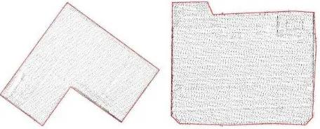
Outline construction starts with the generation of alpha shapes for the given segments (Edelsbrunner and Mücke, 1994). The points that lie inside the alpha shape can be disregarded from further processing. The alpha shapes of two example buildings are shown in Figure 6.
Figure 6. Alpha shapes of two building outlines with overlaid building points.
At close view, the alpha shapes appear very jagged and there is a need for their generalization. Therefore, the outlines are first smoothed using the Douglas Peucker algorithm (Douglas and Peucker, 1973), which discards points without altering the general shape. Then a quadratic least squares adjustment is performed on the remaining line segments, taking the discarded intermediate points into account, minimizing their perpendicular distance to the line (see e.g. (Kreyszig, 1983)). The new point positions are then the intersection of the adjusted lines regarded in consecutive order (cp. Figure 7).
Figure 7. Building outlines after simplification.
The sides of the outlines are now longer line segments, but they are still composed of too many parts, which are also oriented in slightly different directions. To rectify these line segments, a histogram of discrete directions is computed, taking all original points into account as a weight value. Because building corners have mostly 90- and 45-degree angles, the histogram values are computed modulo 45. The centre of the range that sums up to the highest value of the histogram is considered the building’s main orientation. Each line segment is then assigned the closest direction value that is a multiple of 45 degrees compared to the main direction. If two consecutive line segments have the same direction value, then they are combined and checked once more against the main directions. If the direction is too far off and the line segment has a minimum length, then the segment keeps its varying direction, otherwise it is adjusted once more to the main direction to best fit its original points. Figure 8 shows the resulting outlines of the example buildings.
Figure 8. Building outlines after generalization.
The outline generation approach has also been tested on a larger data set. Figure 9 shows the resulting outlines overlaid to the original building points. The building outlines fit tightly around the points, restricted to the main directions wherever possible.
Figure 9. Reconstructed building outlines.
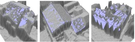
To have an early impression of how the outlines will perform in conjunction with sub-surface growing, we have prototypically applied them to the segments of flat roof office buildings. The 3D model construction is done in layers, the lowest layer spanning the whole building footprint. Every overlying layer being smaller than the previous; skipping layers that feature too few differences. The main directions of the building are propagated from lower to higher layers, resulting in a sound rectification of the whole building. Figure 10 shows some example buildings.
Figure 10. Reconstructed office buildings.
In order to be useful for sloped roofs, it must be possible to provide a main direction that comes e.g. from the ridgeline direction. Otherwise the eaves and gables will be distorted in comparison to the ridge. This will be part of future work.
5. RESULTS
As of the time of writing this article, we have not yet fully implemented a reconstruction pipeline. The segmentation with sub-surface growing is functional and the shape identification and 3D model construction stages are in a prototypical stage and work with gable and flat roofs. But although the results we present are preliminary, we have been able to produce models of buildings with complex roof shapes. Because of sub-surface growing, the identification of gable roofs and their relations to adjacent gable roofs are very reliable and flexible. See e.g. Figure 11 to Figure 14 for some example buildings with complex gable roof structures.
Figure 11. Digital surface model and reconstructed building.
Figure 12 Digital surface model and reconstructed building.
Figure 13. Three examples of automatically reconstructed 3D building models.
Figure 14. Three examples of automatically reconstructed 3D building models overlaid with digital surface model.
6. CONCLUSION
Sub-surface growing is a very general extension to point cloud segmentation. It aims to improve the identification of roof parts by allowing lower segments to grow beneath higher ones. Thus generating fewer and larger segments that grow closer together, show stronger adjacency relations, therefore form more distinct ridgelines, and allow for fewer and stricter thresholds. The interpretation of roof shapes and their composition to more complex shapes becomes more reliable and a larger number of configurations can be differentiated.
Some of the discussed problems might also be solvable by target graph matching to help identify roof shapes. So what we present could be regarded as an alternative approach that tackles the same problems at an earlier stage of the reconstruction pipeline. It would be very interesting to combine both methods to see where either one is superior to the other or how they can be combined for maximum benefit.
There have been other approaches that already proposed using primitives and combine them with CSG for model construction. But just combining primitives alone is not powerful enough and the resulting models tend to have excessive parts sticking out. Especially the generation of corners is difficult. Sub-surface growing helps to ensure that the elongated parts actually lie underneath other primitives and will not show in the final model. And the trimming of primitives with halfspace volumes allows to better make primitives fit together.
The 3D building generation is still heavily under construction. Our boundary generalization approach allows us to generate 2D building footprints and flat roof 3D building models from sub-surface segments. Once it has been fully integrated into the processing pipeline, it will be a large step forward. But we feel that the outline generalization is still not thorough enough for all shapes and needs further tweaking.
7. REFERENCES
Baltsavias, E.P., 2004. Object extraction and revision by image analysis using existing geodata and knowledge: current status
and steps towards operational systems. ISPRS Journal of Photogrammetry and Remote Sensing 58 (3–4), pp. 129–151.
Brenner, C., 2005. Building reconstruction from images and laser scanning. In: International Journal of Applied Earth Observation and Geoinformation 6 (3–4), pp. 187–198.
Brenner, C., 2010. Building extraction. In: George Vosselman, Hans-Gerd Maas (eds.) Airborne and Terrestrial Laser Scanning, Whittles Publishing, pp. 169-212.
Douglas, D. and Peucker, T., 1973. Algorithms for the reduction of the number of points required to represent a digitized line or its caricature. In: The Canadian Cartographer, Vol. 10, pp. 112-122.
Edelsbrunner, H. and E. P. Mücke, E.P., 1994. Three-dimensional alpha shapes. In: ACM Trans. Graph., Vol. 13 (1), pp. 43-72.
Haala, N., Kada, M., 2010. An update on automatic 3D building reconstruction. In: ISPRS Journal of Photogrammetry and Remote Sensing, Vol. 65 (6),pp. 570-580.
Kreyszig, E., 1983. Advanced Engineering Mathematics (5th edn.), John Wiley & Sons, New York.
Möser, S., Wahl, R., Klein, R., 2009. Out-of-core topologically constrained simplification for city modeling from digital surface models. The International Archives of the Photogrammetry, Remote Sensing and Spatial Information Sciences 38 (Part 5/W1) (on CD-ROM).
Oude Elberink, S., Vosselman, G., 2009. Building reconstruction by target based graph matching on incomplete laser data: analysis and limitations. Sensors 9, pp. 6101–6118.
Park, J., Lee, I., Choi, Y., Lee, Y.J., 2006. Automatic extraction of large complex buildings using LiDAR data and digital maps. In: The International Archives of the Photogrammetry, Remote Sensing and Spatial Information Sciences 36 (Part 3), pp. 148– 154.
Rothermel, M., Haala, N., 2011. Potential of dense matching for the generation of high quality digital elevation models. In: ISPRS Hannover Workshop 2011: High-Resolution Earth Imaging for Geospatial Information, IASPRS, Volume XXXVIII-4/W19.
Rottensteiner, F., 2006. Consistent estimation of building parameters considering geometric regularities by soft constraints. In: The International Archives of the Photogrammetry, Remote Sensing and Spatial Information Sciences 36 (Part 3), pp. 13–18.
Sohn, G., Huang, X., Tao, V., 2008. Using a binary space partitioning tree for reconstructing polyhedral building models from airborne LiDAR data. In: Photogrammetric Engineering & Remote Sensing 74 (11), pp. 1425–1438.
Verma, V., Kumar, R., Hsu, S., 2006. 3D building detection and modeling from aerial LiDAR data. In: Proceedings of the 2006 IEEE Computer Society Conference on Computer Vision and Pattern Recognition. CVPR’06. IEEE Computer Society, Washington, DC, pp. 2213–2220.
Vosselman, G., 2010. Visualisation and structuring of point clouds. In: George Vosselman, Hans-Gerd Maas (eds.) Airborne and Terrestrial Laser Scanning, Whittles Publishing, pp. 45-81.