Komunikasi Data
Data Link
Control
SAP Komunikasi Data
Pendahuluan Protokol dan Arsitektur
Transmisi Data dan Media
Transmisi
Pengkodean Data Komunikasi Data
Digital Data Link Control
Switchin g
Multiplexing Komputer Jaringan
Spread Spectrum Start Finish UTS UU/UAS Tugas 1 Tugas 2
“A conversation forms a two-way communication
link; there is a measure of symmetry between the two
parties, and messages pass to and fro. There is a
continual stimulus-response, cyclic action; remarks
call up other remarks, and the behavior of the two
individuals becomes concerted, co-operative, and
directed toward some goal. This is true
communication.”
—On Human Communication
,
Data Link Control Protocols
•
Pengiriman data melalui
link komunikasi data
yang terlaksana dengan penambahan kontrol
layer dalam tiap device komunikasi,
dinyatakan sebagai
data link control
atau
data link protocol
.
•
Data link
adalah medium tramsmisi antara
stasiun-stasiun ketika suatu prosedur data link
control dipakai.
Data Link Control Protocols
• Kebutuhan dan tujuan untuk komunikasi data secara efektif antara
dua koneksi stasiun transmisi-penerima secara langsung terdiri dari :
Frame synchronization Flow control
Error control Addressing
Control and data Link management
Frame synchronization
•
Data dikirim dalam blok-blok yang disebut
frame. Awal dan akhir tiap frame harus dapat
diidentifikasikan.
Flow Control
•
Flow control
:
stasiun pengirim harus tidak mengirim
frame-frame pada rate/kecepatan yang lebih cepat
daripada stasiun penerima yang dapat
menyerapnya.
•
Adalah suatu teknik untuk
memastikan/meyakinkan bahwa suatu stasiun
transmisi tidak menumpuk data pada suatu
stasiun penerima.
•
Tanpa flow control, buffer dari receiver akan
penuh sementara sedang memproses data lama.
Karena ketika data diterima, harus dilaksanakan
sejumlah proses sebelum buffer dapat
Frame 1 Source Destination T im e Frame 1 Frame 2 Frame 2 Frame 3 Frame 3 Frame 4 Frame 4 Frame 5
(a) Error-free transmission
Figure 7.1 Model of Frame Transmission
Frame 5 Frame 1 Source Destination Frame 1 Frame 2 Frame 3 Frame 3 Frame 4 Garbled frame Frame 5 (b) Transmission with losses and errors
Frame 5
tiap tanda panah
menyatakan suatu
perjalanan frame
tunggal. Suatu data
link antara dua
stasiun dan
transmisinya bebas
error. Tetapi
bagaimanapun,
setiap frame yang
ditransmisi
semaunya dan
sejumlah delay
sebelum diterima.
Stop-and-Wait Flow Control
•
Bentuk sederhana dari
flow control
• Cara kerjanya :
Suatu entity sumber mentransmisi suatu frame. Setelah diterima, entity tujuan memberi isyarat untuk menerima frame lainnya dengan mengirim acknowledgment ke frame yang baru diterima. Sumber harus menunggu sampai menerima acknowledgment sebelum mengirim frame berikutnya. Entity tujuan kemudian dapat menghentikan aliran data dengan tidak memberi acknowledgment.
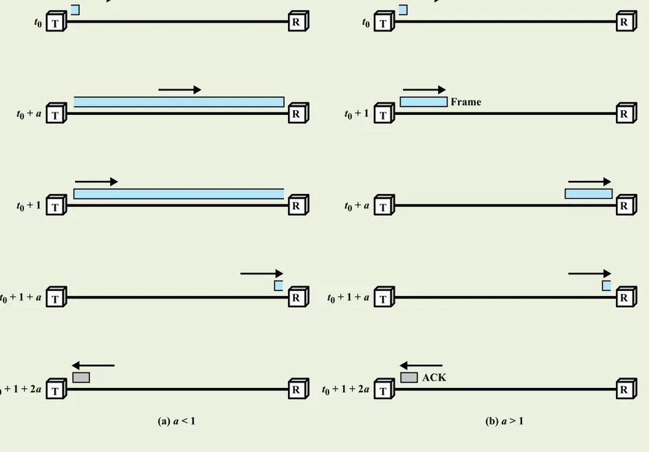
t0 T R T R t0 + 1 T R T R t0 + a T R T R t0 + 1 + a T R T R t0 + 1 + 2a ACK Frame t0 t0 + a t0 + 1 t0 + 1 + a t0 + 1 + 2a T R T R (b) a > 1 (a) a < 1
Penjelasan Gambar 7.2
• Menggambarkan efek penggunaan a .• Gambar 7.2a (a<1) dimana panjang bit lebih kecil daripada frame.
• Pada saat t0, stasiun mulai mentransmisi suatu frame.
• Pada t0+a, leading edge dari frame mencapai stasiun penerima, sementara stasiun pengirim masih melakukan proses transmisi frame.
• Pada t0+1, stasiun pengirim sudah mentransmisi secara lengkap.
• Pada t0+1+a, stasiun penerima sudah menerima seluruh frame dan langsung mentransmisi suatu frame acknowledgment yang pendek. Acknowledgment ini tiba kembali di stasiun pengirim pada t0+1+2a. Jadi total waktu penyebaran : 1 + 2a.
• Total waktu transmisi : 1. Sehingga efisiensi : U = 1 + 2a Hasil yang sama dicapai juga dengan a>1, yang digambarkan pada gambar 7.2b.
Contoh
•
Pada local network dimana transmisi data digital melalui
modem; dimana:
– data rate = 9600 bps
– karena range jarak dari 0,1 – 10 Km
– dengan data rate 0,1 – 10 Mbps
– maka dipakai V = 2x10⁸ m/s;
– ukuran frame yang dipakai 500 bit;
– jika dipakai pada jarak pendek d = 100 m, maka a = 9600 bps x 100 m = 9,6x10⁻⁶ dan pemakaiannya efektif 2x10⁸ m/s x 500 bits – Jika dipakai pada jarak yang jauh d = 5000 Km, maka a = 9600 x
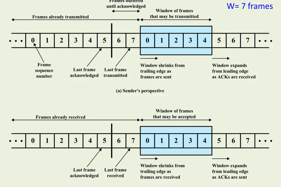
Sliding Windows Flow Control
•
Mengizinkan beberapa frame bernomor dalam
transit
–
Receiver memiliki buffer W panjang
–
Transmitter mengirim hingga W frame tanpa ACK
–
ACK mencakup jumlah frame berikutnya yang diharapkan
–
Nomor urut dibatasi oleh ukuran bidang (k)
• Frame diberi nomor modulo 2k
• Memberikan ukuran window size 2k – 1
–
Penerima dapat ACK frame tanpa mengizinkan
transmisi lebih lanjut (Receive Not Ready)
•
Harus mengirim tanda terima yang normal
untuk melanjutkan
Figure 7.3 Sliding-Window Depiction
0 1 2 3 4 5 6 7 0 1 2 3 4 5 6 7
Window of frames that may be transmitted Frames already transmitted
Frames buffered until acknowledged Last frame transmitted Last frame acknowledged Frame sequence number
Window shrinks from trailing edge as frames are sent
Window expands from leading edge as ACKs are received (a) Sender's perspective
0 1 2 3 4 5 6 7 0 1 2 3 4 5 6 7
Window of frames that may be accepted Frames already received
Last frame received Last frame
acknowledged
Window shrinks from trailing edge as frames are received
Window expands from leading edge as ACKs are sent (b) Receiver's perspective
Penjelasan Gambar 7.3
•
Menunjukkan proses sliding-window. Anggap dipakai 3
bit penomoran, maka terdapat 0-7 nomor.
•
Pada gambar, pengirim dapat mentransmit 7 buah
frame, yang dimulai dengan frame ke 6.
•
Setiap kali frame dikirim, daerah dalam kotak akan
menyusut; setiap kali sebuah acknowledgment
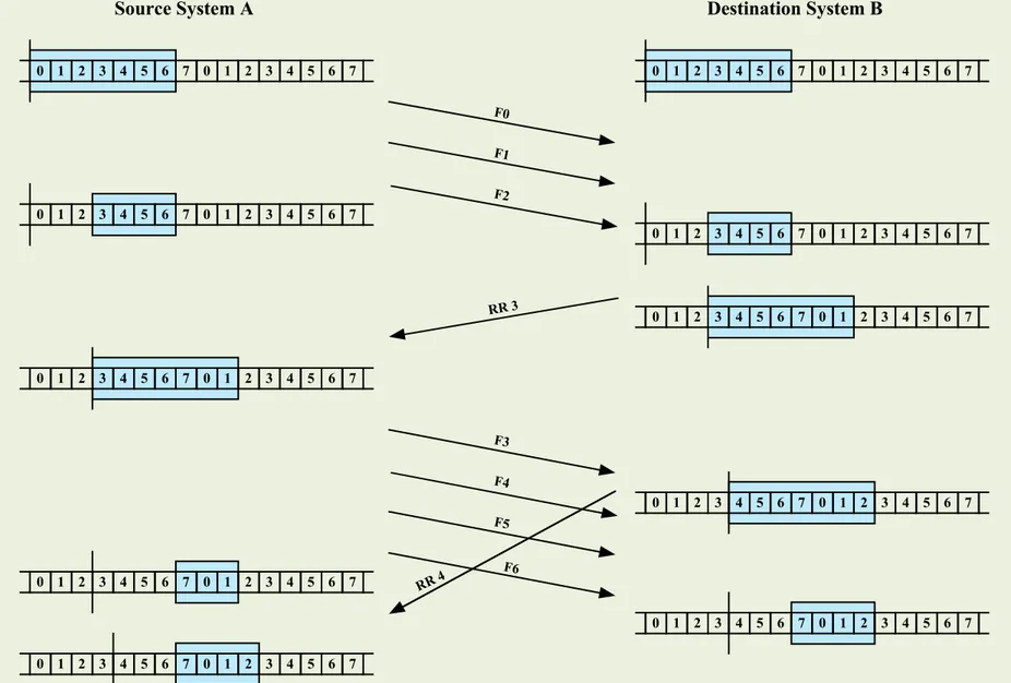
F0 F1 F2 RR 3 F3 F4 F5 F6 RR 4
Source System A Destination System B
Figure 7.4 Example of a Sliding-Window Protocol
0 1 2 3 4 5 6 7 0 1 2 3 4 5 6 7 0 1 2 3 4 5 6 7 0 1 2 3 4 5 6 7 0 1 2 3 4 5 6 7 0 1 2 3 4 5 6 7 0 1 2 3 4 5 6 7 0 1 2 3 4 5 6 7 0 1 2 3 4 5 6 7 0 1 2 3 4 5 6 7 0 1 2 3 4 5 6 7 0 1 2 3 4 5 6 7 0 1 2 3 4 5 6 7 0 1 2 3 4 5 6 7 0 1 2 3 4 5 6 7 0 1 2 3 4 5 6 7 0 1 2 3 4 5 6 7 0 1 2 3 4 5 6 7 0 1 2 3 4 5 6 7 0 1 2 3 4 5 6 7
Penjelasan Gambar 7.4
• menunjukkan suatu contoh, dimana dianggap ada 3 bit penomoran dan suatu ukuran window maksimum sebesar 7.
• A dan B mempunyai window yang mengindikasi bahwa A boleh mengirim 7 buah frame, dimulai dengan frame ke 0 (f0).
• Setelah mengirim 3 buah frame (f0,f1,f2) tanpa acknowledgment, A telah menyusutkan windownya menjadi 4 buah frame.
• Window ini menyatakan bahwa A boleh mentransmit 4 buah frame, dimulai dengan frame nomor 3; pada kenyataannya, saya siap
menerima 7 frame, yang dimulai dengan frame nomor 3.
• "Dengan acknowledgment ini, A kembali meminta izin untuk mentransmisi 7 frame masih, diawali dengan frame 3. A mulai
mentransmisi frame 3, 4, 5 dan 6. B mengembalikan ACK 4, dimana mengakui frame 3, dan mengizinkan transmisi frame 4 sampai 2.
• Tetapi, pada waktu acknowledgment mencapai A, A sudah
mentransmisi frame 4, 5 dan 6. Kesimpulannya bahwa A hanya boleh membuka window-nya untuk memperkenankan transmisi dari 4 frame, dimulai dengan frame 7.
Error Control Techniques
Error
detection acknowledgment Positive
Retransmission after timeout
Negative
acknowledgment and retransmission
Frame hilang : suatu frame gagal mencapai sisi yang lain
Frame rusak : suatu frame tiba tetapi beberapa bit-bit-nya error.
Automatic Repeat Request (
ARQ
)
•
Collective name for
error control
mechanisms
•
Effect of ARQ is to
turn an unreliable
data link into a
reliable one
Stop-and-wait
Go-back-N
Selective-reject
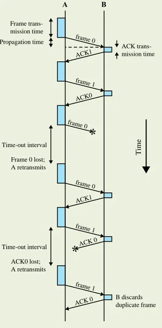
Stop and Wait ARQ
Source transmits single frame
Waits for ACK • No other data can be sent until destination’s reply arrives
If frame received is damaged, discard it • Transmitter has timeout • If no ACK within timeout, retransmit If ACK is damaged, transmitter will not recognize
• Transmitter will retransmit • Receiver gets two copies of
frame
• Use alternate numbering and ACK0 / ACK1
frame 0 ACK1 frame 1 ACK0 frame 1 ACK 0 frame 0 ACK1 frame 1 Frame trans-mission time ACK trans-mission time Propagation time Time-out interval Frame 0 lost; A retransmits Time-out interval ACK0 lost; A retransmits B discards duplicate frame
Figure 7.5 Stop-and-Wait ARQ
frame 0 ACK 0 T im e A B
Stasiun
sumber
mentransmisi
suatu frame tunggal dan kemudian
harus
menunggu
suatu
acknowledgment
(ACK)
dalam
periode tertentu. Tidak ada data
lain dapat dikirim sampai balasan
dari stasiun tujuan tiba pada
stasiun sumber. Bila tidak ada
balasan maka frame ditransmisi
ulang. Bila error dideteksi oleh
tujuan, maka frame tersebut
dibuang dan mengirim suatu
Negative Acknowledgment (NAK),
yang
menyebabkan
sumber
mentransmisi ulang frame yang
rusak tersebut.
Go-Back-N ARQ
•
Most commonly used error control
•
Based on sliding-window
•
Use window size to control number of
outstanding frames
•
While no errors occur, the destination will
acknowledge incoming frames as usual
–
RR=receive ready, or piggybacked acknowledgment
•
If the destination station detects an error in a
frame, it may send a negative acknowledgment
–
REJ=reject
–
Destination will discard that frame and all future
frames until the frame in error is received correctly
–
Transmitter must go back and retransmit that frame
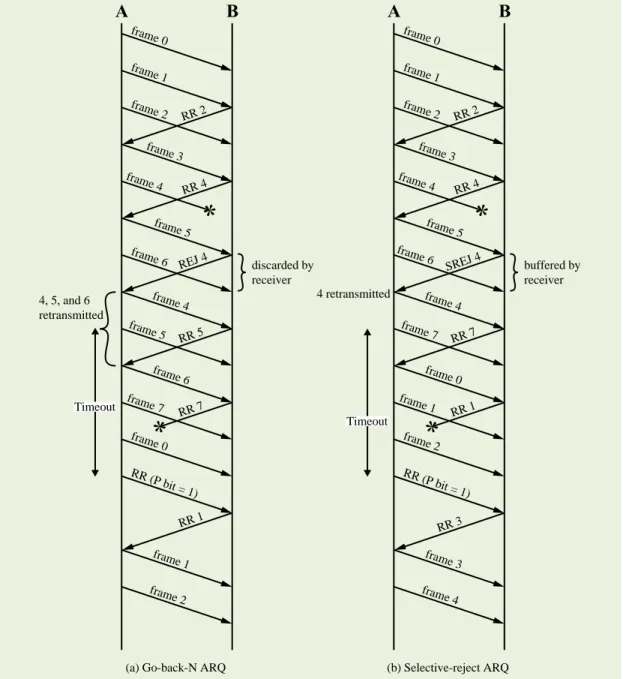
Selective-Reject (ARQ)
•
Also called selective retransmission
•
Only rejected frames are retransmitted
•
Subsequent frames are accepted by the receiver and
buffered
•
Minimizes retransmission
•
Receiver must maintain large enough buffer
•
More complex logic in transmitter
–
Less widely used
Selective-Reject (ARQ)
•
Window Size Limitation
–
For a k-bit sequence number, the maximum window size
is limited to 2
k-1.
0 1 2 3 4 5 6 7 0 1 2 3 4 5 ... S R RR7 lost retx
0 1 2 3 4 5 6 7 0 1 2 ... S R RR4 lost retxx
k=3, W=7 k=3, W=4RR (P bit = 1) RR 2 RR 4 REJ 4 RR 5 RR 1 frame 0 frame 1 frame 2 frame 3 frame 5 frame 6 frame 4 frame 5 frame 6 frame 7 frame 0 frame 1 frame 2 frame 4 RR 7
(a) Go-back-N ARQ 4, 5, and 6 retransmitted discarded by receiver Timeout RR (P bit = 1) RR 2 RR 4 SREJ 4 RR 7 RR 3 frame 0 frame 1 frame 2 frame 3 frame 5 frame 6 frame 4 frame 7 frame 0 frame 1 frame 2 frame 3 frame 4 frame 4 RR 1 (b) Selective-reject ARQ 4 retransmitted buffered by receiver Timeout
Figure 7.6 Sliding-Window ARQ Protocols
High Level Data Link Control (HDLC)
Most important data link control protocol
Specified as ISO 3009, ISO 4335
Basis for other data link control protocols
Station types
Primary - controls operation of link
Secondary - under control of primary station
Combined - issues commands and responses
Link configurations
Unbalanced - 1 primary, multiple secondary
HDLC Data Transfer Modes
Normal Response Mode (NRM)
• Used with an unbalanced configuration• Primary initiates transfer
Asynchronous Balanced Mode (ABM)
• Used with a balanced configuration
• Either station initiates transmission
• Has no polling overhead
• Most widely used
Asynchronous Response Mode (ARM)
• Used with unbalanced configuration
• Secondary may transmit without permission from primary
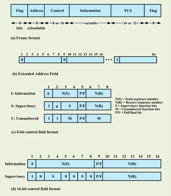
Flag FCS Information Control Address Flag 8 bits 8 extendable 8 or 16 variable 16 or 32 8 (a) Frame format
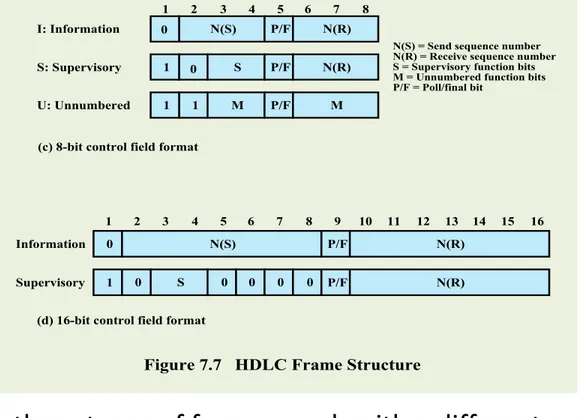
I: Information S: Supervisory U: Unnumbered 1 2 3 4 5 6 7 8 N(R) N(R) M N(S) S M 0 0 1 1 1 P/F P/F P/F
N(S) = Send sequence number N(R) = Receive sequence number S = Supervisory function bits M = Unnumbered function bits P/F = Poll/final bit
(c) 8-bit control field format
Information 0 N(S) P/F N(R)
1 2 3 4 5 6 7 8 9 10 11 12 13 14 15 16
Supervisory 1 0 S 0 0 0 0 P/F N(R) (d) 16-bit control field format
Figure 7.7 HDLC Frame Structure
0
1 2 3 4 5 6 7 8 9 10 11 12 13 14 15 16 8n
0 1
Original Pattern:
111111111111011111101111110
After bit-stuffing
1111101111101101111101011111010
Address Field
•
Identifies secondary station that transmitted or will
receive frame
•
Usually 8 bits long
•
May be extended to multiples of 7 bits
–
Leftmost bit indicates if is the last octet (1) or not (0)
•
Address 11111111 allows a primary to broadcast a
frame for reception by all secondaries
Flag FCS Information Control Address Flag 8 bits 8 extendable 8 or 16 variable 16 or 32 8
(a) Frame format
I: Information S: Supervisory U: Unnumbered 1 2 3 4 5 6 7 8 N(R) N(R) M N(S) S M 0 0 1 1 1 P/F P/F P/F
N(S) = Send sequence number N(R) = Receive sequence number S = Supervisory function bits M = Unnumbered function bits P/F = Poll/final bit
(c) 8-bit control field format
Information 0 N(S) P/F N(R)
1 2 3 4 5 6 7 8 9 10 11 12 13 14 15 16
Supervisory 1 0 S 0 0 0 0 P/F N(R)
(d) 16-bit control field format
Figure 7.7 HDLC Frame Structure
0
1 2 3 4 5 6 7 8 9 10 11 12 13 14 15 16 8n
0 1
(b) Extended Address Field
• HDLC defines three types of frames, each with a different control field format
– Information frames (I-frames)
Carry the data to be transmitted for the user
Flow and error control data, using the ARQ mechanism, are piggybacked on an
information frame
– Supervisory frames (S-frames)
• Provide the ARQ mechanism when piggybacking is not used
– Unnumbered frames (U-frames)
Control Field
•
Use of poll/final (P/F) bit depends on context
•
In command frames P bit is set to 1 to solicit (poll) a
response from the peer HDLC entity
•
In response frames F bit is set to 1 to indicate the
response frame transmitted as a result of a soliciting
command
•
The basic control field for S- and I-frames uses 3 bit
sequence numbers
–
An extended control field can be used that employs 7-bit
sequence numbers
Information and Frame Check
Sequence (FCS) Fields
Information Field
Present only in I-frames and some U-frames
Must contain an integral number of octets
Variable length
Frame Check
Sequence Field (FCS)
Error detecting code calculated from the remaining bits of the frame, exclusive of
flags
The normal code is the 16 bit CRC-CCITT
Optional 32-bit FCS, using CRC-32, may be employed if the frame length or the
Name Command/ Response
Description
Information (I) C/R Exchange user data
Supervisory (S)
Receive ready (RR) C/R Positive acknowledgment; ready to receive I-frame
Receive not ready (RNR) C/R Positive acknowledgment; not ready to receive Reject (REJ) C/R Negative acknowledgment; go back N
Selective reject (SREJ) C/R Negative acknowledgment; selective reject
Unnumbered (U)
Set normal response/extended mode (SNRM/SNRME)
C Set mode; extended = 7-bit sequence numbers
Set asynchronous response/extended mode (SARM/SARME)
C Set mode; extended = 7-bit sequence numbers
Set asynchronous balanced/extended mode (SABM, SABME)
C Set mode; extended = 7-bit sequence numbers
Set initialization mode (SIM) C Initialize link control functions in addressed station
Disconnect (DISC) C Terminate logical link connection
Unnumbered Acknowledgment (UA) R Acknowledge acceptance of one of the set-mode commands
Disconnected mode (DM) R Responder is in disconnected mode Request disconnect (RD) R Request for DISC command
Request initialization mode (RIM) R Initialization needed; request for SIM command Unnumbered information (UI) C/R Used to exchange control information
Unnumbered poll (UP) C Used to solicit control information Reset (RSET) C Used for recovery; resets N(R), N(S) Exchange identification (XID) C/R Used to request/report status
Test (TEST) C/R Exchange identical information fields for testing Frame reject (FRMR) R Report receipt of unacceptable frame
Table 7.1
HDLC
Commands
and
Responses
(Table can be found on page 254 in the textbook)
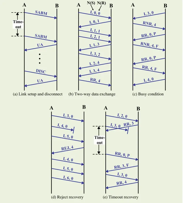
HDLC Operation
Init ia liz at ionSignals the other side that initialization is requested Specifies which of the three modes (NRM, ABM, ARM) is requested
Specifies whether 3- or 7-bit sequence numbers are to be used Da ta Tr an sf er
The N(S) and N(R) fields of the I-frame are sequence numbers that support flow control and error control An HDLC module will number them sequentially Receive Ready (RR) is used when there is no reverse
user data traffic Disc
onn
ect
Either module can initiate
•Either on its own
initiative if there is some sort of fault, or at the request of its higher-layer user
Sends disconnect (DISC) frame
Remote entity replies with a UA
Any outstanding unacknowledged I-frames may be lost
•Recovery is the
responsibility of higher layers
Consists of the exchange of I-frames, S-frames and
U-frames
A B I, 0, 0 I, 1, 1 I, 2, 1 I, 3, 2 RR, 4 I, 0, 1 I, 1, 3 I, 3, 4 I, 2, 4
(b) Two-way data exchange
A B RNR, 4 RNR, 4, F RR, 4, F I, 3, 0 RR, 0, P I, 4, 0 RR, 0, P (c) Busy condition A B I, 3, 0 I, 4, 0 I, 5, 0 I, 4, 0 I, 6, 0 I, 5, 0 REJ, 4 (d) Reject recovery A B I, 2, 0 RR, 0, P I, 3, 0 RR, 3 RR, 4 RR, 3, F
(e) Timeout recovery
Time-out A B SABM SABM UA DISC UA
(a) Link setup and disconnect
I, 3, 0
Time-out
Figure 7.9 Examples of HDLC Operation