NETWORK INTERFACES AND FUZZY-LOGIC CONTROL FOR
A MECANUM-WHEELED OMNI-DIRECTIONAL ROBOT
Author: Samuel A. Miller
Advisor: Dr. Arthur T. Bradley, NASA Langley Research Center
Advisor: Dr. Linda L. Vahala, Old Dominion University
March 26, 2005
Abstract
This paper presents the results of a project to develop an omni-directional robotic system at NASA Langley’s Robotics and Intelligent Machines Lab. The robot, named Mobius, was created as part of an investigation into omni-directional motion (using four Mecanum wheels) and fuzzy-logic control. The robot uses a high-level processor running Linux to connect to wireless networks, process user-input data, relay camera imagery, and communicate with a low-level microcontroller. All the programs for user input and imagery viewing are cross-platform, Internet-enabled, client-server applications. When within range of a wide-area-network wireless access point, Mobius can be driven from an arbitrary location on the Internet. Low-level control of Mobius’ motors is through a simple microcontroller-based fuzzy-logic algorithm. The robot platform is capable of translation in any direction, bidirectional rotation, and simultaneous translation with rotation. Future work includes constructing a vehicle with three Mecanum wheels and autonomous algorithms. The algorithms will fuse sonar ranging with stereoscopic and panoramic imagery for autonomous robot navigation and topologic robot localization.
Introduction
In January of 2004 NASA was given a Presidential directive to “gain a new foothold on the moon and to prepare for new journeys to worlds beyond our own.” Without question this new vision for space will extensively utilize robotic systems for many aspects of its realization. At NASA Langley Research Center’s Robotics and Intelligent Machines Lab we are particularly interested in a class of robotic vehicles with holomonic (omni-directional) motion capability. We expect these types of vehicles, whether manned, tele-operated or autonomous, will find many uses in the confined spaces of off-planet habitats, just as they are useful in earth-based facilities including nuclear plants, factory workshops, and warehouses.1
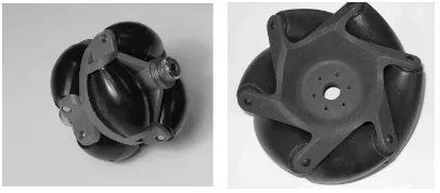
Holomonic vehicles can be classified as using steerable wheels2 or specialty wheels.3-5 Steerable-wheel systems generally require wheel reorientation to switch direction, while specialty-wheel designs generally operate on a controlled sliding principle. Two specialty-wheel examples are the “universal”6 and “Mecanum”7 designs shown in Figure 1. Both wheel types provide resistance in one direction, while allowing free motion in the other. The net force acting on the vehicle body from multiple wheels is precisely controllable by varying the individual wheel velocities. In general, steerable wheels have greater motion efficiency then specialty wheels, because components of individual specialty-wheel s’ forces are canceled to generate a net force on the vehicle. This disadvantage is generally eclipsed by the mechanical simplicity of the non-dynamic wheel mounting generally employed.
Figure 1: Omni (left) and Mecanum (right) wheels
This project utilized the Mecanum wheel design pioneered in 1973 by Mecanum AB’s Bengt Ilon. Our primary goals for the project were to a) gain a better understanding of the tele-operational control issues involved in specialty-wheel based holomonic platforms, b) provide local-area-network (LAN) and Internet-enabled tele-operation capabilities, c) demonstrate fuzzy-logic closed-loop control for Mecanum-wheeled systems, and d) implement a high-level software system for robust, platform-independent tele-operational control.
Mechanical Configuration
vehicle depends on each wheel resting firmly on the ground, some are equipped with suspension systems. For simplicity our robot Mobius (Figure 2) has no suspension; the wheel/motor assemblies are mounted directly on the aluminum frame. The wheel-base and the track are both 16 inches.
Figure 2: Mobius with plastic shell, and without
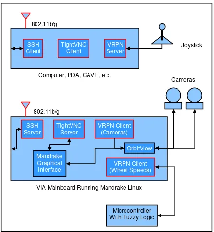
Mobius was designed primarily as a platform to explore tele-operational omni-directional motion. To handle user input and feedback, we chose a 600 MHz single-board computer running Linux. It provides a rich environment to experiment with different interaction methodologies. (The computer – by VIA Technologies, Inc. – is typically used in standalone DVD players.) The system hardware architecture (Figure 3) shows the connections between this main computer and the other hardware components of the robot.
Figure 3: Hardware system components
The robot’s motors have built-in 15:1 gear reductions, and optical encoders provide velocity information to the micro-controller. Closed-loop wheel-speed control using fuzzy logic is implemented on the microcontroller, which receives high-level wheel-speed commands from the main processor.
The main processor calculates the ideal individual wheel-speeds from user input on a three-axis joystick. The joystick (currently a standard 2.4GHz wireless unit from Logitech) can connect directly to the robot’s main computer, or to another computer on the network,
which transmits the data to the robot using an 802.11b/g connection.
Kinematics
There are multiple ways to derive the kinematic relationship between the joystick values and the ideal wheel speeds (the fuzzy-logic control-loop set-points). However, for Mobius’ particular wheel arrangement the following simple derivation provides remarkably intuitive control, and efficient software implementation. Choosing the robot reference frame for control inputs is an important consideration. For autonomous operation the “global reference” frame of Figure 4 might have significant importance, and [8,9] provide ample detail in that regard. For tele-operation, however, Figure 4’s “vehicle reference” provides a natural tele-operational experience, especially when the robot is driven using only the onboard pan-and-tilt cameras.
Figure 4: Possible robot reference frames and wheel force vectors
For Mobius’ square wheel-base a third “wheel reference,” (the user reference rotated -45°) lends itself to simplified kinematic analysis. If the user reference axes are x and y then the wheel reference are
θ θ
θ θ
cos sin
sin cos
' '
' '
y x
y
y x
x
+ =
−
= (1)
where x´ and y´ are the wheel reference axes.
In this setting we first derive the kinematics for translation with no rotation, and then linearly combine a separate rotation component.
The force vector required to accelerate the robot in a particular direction is
(
)
(
)
[
w1 w4 xˆ ' w2 w3 yˆ']
Kwhere wi is the force exerted on the vehicle by the ith
wheel, KT is a user-defined scalar-valued sensitivity
constant, and
x
ˆ
'
andy
ˆ
'
are unit vectors along the wheel reference axes.When Equation (2) is shifted by Equation (1) the force on the robot in the user reference axes is
(
) (
)
[
]
(
) (
)
[
]
+ + + + + − + = ˆ ˆ 2 2 3 2 4 1 3 2 4 1 y w w w w x w w w w KFa T (3)
When considering translation the robot must not rotate: we accomplish this by forcing diagonally opposite wheels to exert equal forces (spin at the same speeds). Although other non-rotation conditions exist, forcing diagonally opposite wheels to spin at the same rate provides the best load-sharing between the motors, without limiting translation capabilities. The above condition results in w1 = w4 and w2 = w3 and the
following expression for the net force.
(
) (
)
[
]
[
(
) (
)
]
{
}
(
)
(
)
{
ˆ ˆ}
2 ˆ 2 2 ˆ 2 2 2 2 2 1 2 1 2 1 2 1 y w w x w w K y w w x w w K F T T a + + − = + + − = (4)The coefficients of x´ and y´ correspond directly to the axis values of a joystick, denoted xj and yj respectively.
(
)
(
1 2)
2 1 2 2 w w K y w w K x T j T j + = − = (5)
Solving these expressions for w1 and w2, and noting that
the wheel forces are related to the wheel velocities (ωi) by
i
i R
w = ω (6)
(where R is the wheel radius) yields the following expressions for wheel velocities in terms of joystick values. T j j T j j RK y x RK y x 2 2 2 2 3 2 4 1 − − = + = = ω ω ω ω (7)
Requiring diagonally opposite wheels to maintain the same rotational velocities forces rotation-less translation. Disturbing that balance by modifying the wheel speeds on each side of the robot (using the joystick z-axis, zj) allows the robot to translate and
rotate at the same time.
R j T j j R j T j j R j T j j R j T j j K z RK y x K z RK y x K z RK y x K z RK y x − + − = − − − = + − = + + = 2 2 2 2 2 2 2 2 4 2 3 1 ω ω ω ω (8)
(KR is a scalar-valued sensitivity constant for rotation.)
These equations provide a convenient and efficient mechanism for controlling simultaneous translation and rotation of the robot and are embedded in the joystick client software discussed in the next section.
Software Configuration
The three main activities Mobius’ high-level software executes are: network connectivity, joystick input acquisition and processing, and video acquisition and display. A Linux operating system (the Mandrake 10.0 distribution) provides the supporting framework for those tasks. While not commonly used in embedded applications, Mandrake Linux is a convenient solution for device integration. It provides a user-friendly environment for integrating low-cost off-the-shelf hardware components (e.g., webcams and joysticks). Also, the vast amount of open-source software available allows rapid application development and integration, and unconstrained implementation flexibility (as the source code is available).
Figure 5: High-level software interactions
Standard wireless networking protocols and tools are used for all aspects of robot tele-operation. Mobius uses the 802.11b/g protocols to transmit video feedback to the user terminal, and to receive joystick input from the user. Depending on availability, it will either connect to an existing wireless access point, or create its own. Tele-operation across the Internet is possible if Mobius is connected to a wide-area network, and local tele-operation is easily realized by connecting a computer directly to the robot’s self-generated wireless access point.
User joystick input to the Linux mainboard is through the Virtual Reality Peripheral Network (VRPN), a client/server input-device architecture. VRPN is a cross platform open-source project designed to provide input-device data-sharing across networks and system architectures. It operates by serving input-device data from one machine, and then allowing clients on remote machines to retrieve the device data for use in generic applications. Mobius runs a VRPN client that connects to a user-specified server using standard Internet protocols and the 802.11b/g wireless link. The client transforms input-device axes values according to equation (8) and sends them to the microcontroller for the low-level control of the robot’s motors.
Logitech pan-and-tilt USB web-cameras provide Mobius’ operator with one or two perspectives of a scene, or if appropriately aimed, a stereoscopic view. The OrbitView camera-control software package displays the 24-bit color imagery from each camera on the Mandrake graphical desktop. Supported resolution/frame-rate combinations range from
160-by-120 at 30 frames-per-second (fps), up to 640-by-480 at 15 fps. At higher resolutions, frame-rate is heavily dependent on processor load, and can fall well below the target 15 fps.
Network viewing of the video feeds is implemented using TightVNC. Like VRPN, TightVNC is an Internet-enabled client/server architecture: it allows remote graphical computer interactions with nearly real-time latency. A TightVNC server on the robot allows remote TightVNC client connections to the Mandrake graphical desktop, with the associated video feeds and camera-control features.
In addition to the software that directly facilitates user interaction with the robot, a network-monitoring application (NetDog) is used to monitor the connection status between Mobius and the user’s computing device. It functions as a network heartbeat, and stops the VPRN wheel-speed client when it detects a network disconnect. The low-level microcontroller interprets this stop as a signal to transition the robot to a zero-velocity state. When a connection to the user’s computing device is re-established, the VRPN wheel-speed client restarts and returns to normal operation. The combination of VRPN, OrbitView, TightVNC, NetDog, and the standard networking protocols (TCP and UDP) they utilize make the high-level software components remarkably portable and platform-independent. Indeed, operation is possible in many modalities, including directly connecting a joystick to the robot (VRPN client/server running on the same machine and no video feed), directly connecting a wireless laptop to the robot’s own access points for streaming video and joystick data, or connecting the robot to a wide-area-network access point and driving it from inside CAVE-like virtual reality devices. In addition, while the current robot’s operating system is Linux, future robots could easily run an alternate operating system such as Windows.
Fuzzy-Logic Wheel-Speed Control
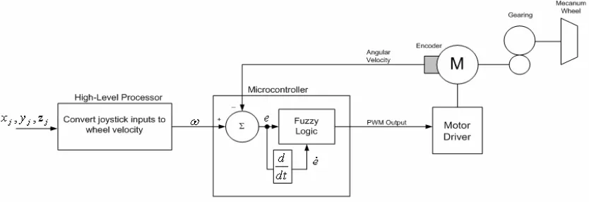
The high-level software outlined above creates a convenient way to manage user input and receive sensor feedback from the robot. These types of tasks have higher latency tolerance than low-level tasks such as motor-speed control. This fact indicates a natural hardware-software partitioning, which we implement by performing low-level motor control with a dedicated microcontroller and a fuzzy-logic algorithm. With the exception of the fuzzy-logic block, our control system in Figure 6 is fairly standard.
VRPN Client (Cameras)
VRPN Client (Wheel Speeds) TightVNC
Server
Mandrake Graphical Interface
OrbitView SSH
Server
VIA Mainboard Running Mandrake Linux
VRPN Server TightVNC
Client SSH
Client
Computer, PDA, CAVE, etc.
Microcontroller With Fuzzy Logic
Joystick
Cameras 802.11b/g
Figure 6: Control system for one wheel
There are many standard methods for controlling the wheel velocity, but, as indicated in Section 1, we were particularly interested in examining the practical performance of fuzzy-logic-based wheel-speed control. In general a fuzzy-logic controller converts linguistic descriptions of control rules, based on the programmer’s “expert knowledge” of the system, into the control values needed by hardware components.10,11 For our particular application, Figure 7 is a diagrammatic representation of the fuzzy-control process. Starting from the lower left, wheel-velocity measurements (from optical encoders) are compared with the desired wheel-velocity values from the VRPN client: the result is a set of linguistic errors. The decision making logic is a set of if-then linguistic rules that result in a set of fuzzy outputs. Each fuzzy output is mapped to a value between 0 and 1 according to their respective membership functions. The actual control value given as input to the system, in this case a single pulse-width-modulated (PWM) motor-driver voltage, is calculate using a defuzzification mapping.
Figure 7: Fuzzy-control process
The process of designing a fuzzy-control algorithm is intrinsically heuristic, and tends to defy concise mathematical representation. For this reason there is only vague mathematical justification for the design choices presented below. (For a more complete treatment of fuzzy-logic theory, applications, and best
practices, the reader is referred to references [10] and [12].)
The following design steps illustrate the methodology we used to create our fuzzy-logic controller.
Step 1: Define linguistic errors in terms of wheel velocities, and fuzzy (linguistic) outputs in terms of motor-driver PWM signals.
Fuzzy Inputs
Error, e = actual wheel speed - commanded wheel speed
N = wheel speed is too slow Z = wheel speed is correct P = wheel speed is too fast
Error rate of change,
e
= current error - previous errorN = error in velocity is increasing Z = error in velocity is not changing P = error in velocity is decreasing Fuzzy Outputs
Speed up, SU = increase PWM duty cycle No change, NC = no change in PWM duty cycle
Slow down, SD = decrease PWM duty cycle Step 2: Define linguistic rules for all possible input/output combinations.
IF e = N AND e = N THEN Output = SU IF e = Z AND e = N THEN Output = SD IF e = P AND e = N THEN Output = SD IF e = N AND e = Z THEN Output = SU IF e = Z AND e = Z THEN Output = NC (9)
IF e = P AND e = Z THEN Output = SD IF e = N AND e = P THEN Output = SU IF e = Z AND e = P THEN Output = SU IF e = P AND e = P THEN Output = SD
have the compact matrix representation shown in Figure 8.
SU
N Z P
N
Z
P
SD SD
SU NC SD
SU SU SD
e
e
SU
N Z P
N
Z
P
SD SD
SU NC SD
SU SU SD
e
e
Figure 8: Linguistic input/output mapping (matrix form)
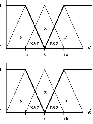
Step 3: Create degree-of-membership fuzzification mappings.
These membership functions associate a weighting with each fuzzy input variable (e and e) in each of the linguistic variables. The “fuzziness” of the methodology comes from the intrinsic overlap between the linguistic variables. For example, from Figure 9 an error e =−a 2 would have DOM values: N = 0.5, Z = 0.5, and P = 0.
N&Z P&Z P N
Z
0 1
e
0 +a
-a
N&Z P&Z P N
Z
0 1
e
0 +a
-a
N&Z P&Z P N
Z
0 1
e
0 +b
-b
N&Z P&Z P N
Z
0 1
e
0 +b
-b
Figure 9: Fuzzy membership functions
Obviously the shapes of the DOM functions have a strong influence on the mapping from e and e to N, M, and P. We chose one of the simplest possible shapes, namely the isosceles triangle. In addition to changing the DOM function shapes, another way to change the DOM mapping is to increasing the number of linguistic variables in Step 1: such a choice would increase the number of triangles in Figure 8.
The a and b values in this setting affect the motor response time and magnitude, and are experimentally determined.
Step 4: For each new input, evaluate the rule base.
For example, e =−a 2corresponds to DOM values: N = 0.5, Z = 0.5, and P = 0. Likewise e = b/2 corresponds to DOM values: N = 0, Z = 0.5, and P = 05.
Evaluating the rule base from Step 2 reveals:
(0.5&0.0) = 0.0 (0.5&0.0) = 0.0 (0.0&0.0) = 0.0 (0.5&0.5) = 0.5
(0.5&0.5) = 0.5 (10)
(0.0&0.5) = 0.0 (0.5&0.5) = 0.5 (0.5&0.5) = 0.5 (0.0&0.5) = 0.0
Step 5: Defuzzify linguistic outputs.
In Step 2 there are a number of relevant rules for each of the linguistic outputs. Specifically for SU: rules 1, 4, 7, and 8; for NC: rule 5; and for SD: rules 2, 3, 6, and 9. The first step in our defuzzification is to produce a scalar for SU, NC, and SD using root-sum-of-squares. For the particular example in Step 4, SU, NC, and SD take on values as shown below.
(
0.0)
2(
0.5)
2(
0.5)
2(
0.5)
2 0.8662 8 2 7 2 4 2 1
= + + + =
+ + +
= R R R R
SU (11)
(
0.5)
2 0.52
5 = =
= R
NC (12)
(
0.0)
2(
0.0)
2(
0.0)
2(
0.0)
2 0.02 9 2 6 2 3 2 2
= + + + =
+ + +
= R R R R
SD (13)
The defuzzified value sent to the motor-driver is determined by weighting the SU, NC, and SD terms by their full-scale values, which in our case were
±
127.5 . 80 0
5 . 0 866 . 0
0 127 5 . 0 0 866 . 0 127
= +
+
⋅ − + ⋅ +
⋅ (14)
lower the error. The process is repeated as part of the microcontroller service loop.
Future Work
Mobius provides a convenient platform for continued development. The combination of a single-board computer running a standard workstation-type operating system allows the exploration of a large number of software possibilities. Currently Mobius is strictly tele-operable via local and wide-area networks. We are implementing an algorithm for topological place recognition:14 the algorithm will allow Mobius to recognize its location based on color-profiles drawn from its environment, which is an important first step towards practical autonomous operation.
We are concurrently developing a companion omni-directional robot that utilizes three instead of four Mecanum wheels. This robot will have the same high-level software and tele-operation architecture as Mobius, but will have a more complete sensor suite for autonomous capabilities. The new sensors include a dedicated high-performance stereo camera, multiple sonar sensors, and a panoramic camera. Because they share the same communication and computing architectures, Mobius and the new robot can freely share information and algorithms. Future utilization of this tight connection to study cooperative behavior-based autonomous algorithms will be an exciting research endeavor.
Conclusions
This paper presented our particular approach to realizing a holomonic robot equipped with Mecanum wheels. The robot’s standard single-board computer, running a Linux workstation operating system, allowed us to use a collection of standard applications for low-latency, tele-operational motion control across local networks and the Internet. Particular care taken in the software selection makes the operator control-system portable to computers ranging from Windows-CE-based PDAs, to desktop workstations, to high-end virtual-reality environments. The efficient equations used to calculate wheel-speeds, combined with the fuzzy-logic wheel-speed control algorithm, make the robot remarkably intuitive to drive. To date over 200 people, from elementary-school children to NASA
engineers, have successfully driven Mobius with only seconds of training.
Acknowledgements
This project was funded by NASA Langley Research Center’s Engineering Directorate Jumpstart Initiative. Special thanks are due Garfield Creary and Nathanael Miller for their mechanical design efforts, and to Noah Misch for his Linux expertise and the NetDog application.
References
[1] Kalpakjian, S., Schmid, S.R., Manufacturing Engineering and Technology, Prentice Hall, 2000.
[2] Boreinstein, J., Everett, H.R., Feng, L., Navigating Mobile Robot, Peters, Wellesley, 1996.
[3] Diegel, O., Badve, A., Bright, G., Potgieter, J., Tlale, S., “Improved Mecanum Wheel Design for Omnidirectional Robots,” Australasian Conference on Robotics and Automation, Auckland, November 2002.
[4] West, M. and Asada, H., “Design of Ball Wheel Mechanisms for Omnidirectional Vehicles with Full Mobility and Invariant Kinematics,” Journal of Mechanical Design, Vol. 119, pp. 153-161, 1997.
[5] Yu, H., Dubowsky, S., Skwersky, A., “Omnidirectional Mobility using Active Split Offset Castors,” ASME Journal of Mechanical Design, 2000.
[6] Blumrich, J.F., “Omnidirectional Vehicle,” US Patent 3,789,947, 1974.
[7] Ilon, B.E., “Wheels for a Course Stable Self-propelling Vehicle Movable in any Desired Direction on the Ground or some other Base,” US Patent 3,876,255, 1975.
[8] Agullo, J., Cardona, S., and Vivancos, “Kinematics of Vehicles with Directional Sliding Wheels,” Mechanical Machine Theory, vol. 22, pp. 295-301, 1987.
[9] Voo, C., “Low Level Driving Routine for the OMNI-Directional Robot,” Honours Dissertation, Centre for Intelligent Information Processing Systems, University of Western Australia, Jan 2000.
[10] Lee, C., “Fuzzy Logic in Control Systems: Fuzzy Logic Controller – Part I,” IEEE Transactions on Systems, Man, and Cybernetics, Vol. 20, No. 2, March 1990.
[11] Baaklini, N., and Mamdani, E.H., “Prescriptive Methods for Deriving Control Policy in a Fuzzy-Logic Controller,” Electron. Letters, Vol. 11, pp. 625-626, 1975.
[12] Passino, K. and Yurkovich, S., Fuzzy Control, Addison-Wesley, 1998.
[13] Ullrich, I., and Nourbakhsh, I., “Appearance-Based Place Recognition for Topological Localization,” IEEE International Conference on Robotics and Automation, San Francisco, pp. 1023-1029, April 2000.