A ROADMAP FOR GENERATING SEMANTICALLY ENRICHED BUILDING MODELS
ACCORDING TO CITYGML MODEL VIA TWO DIFFERENT METHODOLOGIES
G. Floros*, D. Solou, I. Pispidikis and E. Dimopoulou
School of Rural and Surveying Engineering, National Technical University of Athens, 9 Iroon Polytechneiou str, 15780 Zografou, Greece ([email protected]; [email protected]; [email protected]; [email protected])
KEY WORDS : 3D M odeling, Trimble SketchUp, CityEngine, FM E, CityGM L, 3DCitiesProject, 3DCIM ,Semantics
ABS TRACT:
The methodologies of 3D modeling techniques have increasingly increased due to the rapid advances of new technologies. Nowadays, the focus of 3D modeling software is focused, not only to the finest visualization of the models, but also in their semantic features during the modeling procedure. As a result, the models thus generated are both realistic and semantically enriched. Additionally, various extensions of modeling software allow for the immediate conversion of the model’s format, via semi-automatic procedures with respect to the user’s scope. The aim of this paper is to investigate the generation of a semantically enriched Citygml building model via two different methodologies. The first methodology includes the modeling in Trimble SketchUp and the transformation in FM E Desktop M anager, while the second methodology includes the model’s generation in CityEngine and its transformation in the CityGM L format via the 3DCitiesProject extension for ArcGIS. Finally, the two aforesaid methodologies are being compared and specific characteristics are evaluated, in order to infer the methodology that is best applied depending on the different projects’ purposes.
1. INTRODUCTION
Virtual 3D city models have been used in the past, mainly for the visualization or graphical exploration of cityscapes. Nowadays, an increasing number of applications like environmental and training simulations, urban planning and facility management , disaster management and homeland security, and personal navigation require additional information about the city objects given in a standardized representation (Kolbe, 2009). Additionally, the increasing urbanization, the rapid growth of urban areas, and the development of mega cities, are among the important changes occurring in the world. With this increasing urbanization, more than half of the world population will stay in urban areas, counting about 5 billion houses (United Nations, 2008). Therefore, developing new techniques in order to manage the complex urban environment seems to be necessary, along with the development of semantic 3D models, revealing the interrelations of the spatial components of the cities (Sadidi, 2015). Semantics have gradually attracted international scientific interest due to their ability of storing data that describe relations between different object parts and their environment (Diakit́ et al., 2014). This results in a semantically enriched visualization of the reality, or even in a semantic 3D city model. Semantic 3D city models comprise, besides the spatial and graphical aspects, the ontological structure including thematic classes, attributes, and their interrelations. The result is that the semantic modeling of cities requires the appropriate qualification of 3D data (Gr̈ger & Pl̈mer, 2012). Current research and applications focus on the semantic enrichment of distinctive city objects or 3D geometries which can be decomposed into their structural elements including attributes and their correlations. The semantic modeling approach along with the application of 3D geometry and topology of real-world objects is realized by the CityGM L open data model (Kolbe, 2009). However, questions arise about the
* Corresponding author
most effective way to complement the geometries’ semantics or how to efficiently extract semantics from pure geometric models (Zhu et al., 2011), issues which can be addressed by the concept of interoperability. The rapid growth of 3D modeling methodologies and techniques, as well as the development of various 3D formats, have certainly assisted in this direction. Various tools of conversion have been developed. However, none of the converters is currently capable of automatically creating valid geometries nor fully correct semantics, especially when high levels of details are involved (Donkers, 2013). Isikdag and Zlatanova (2009) define a framework automating generation of buildings from BIM to CityGM L, claiming that it is possible to define rules for geometrical transformation and facilitation of semantic matching from IFC to CityGM L models, De Laat and van Berlo (2011) describe the development of GeoBIM extension on CityGM L for IFC data, while El-M ekawy et al., (2011) proposed a unified building model (UBM ) for integration of IFC and CityGM L, allowing bilateral transformation between the two models. Dimopoulou et al., (2014) investigate integration and interoperability options between procedural modeling techniques and BIM -ready software within the CityGM L framework from a semantic viewpoint using ESRI CityEngine environment and Trimble SketchUp Pro software to create 3D building models and evaluate modeling techniques, and Floros et al., (2015) investigate the semantic functionality of conversion methodologies with Trimble SketchUp and FM E up to Level of Detail 4. This paper explores two different methodologies for generating a CityGM L M odel in LoD3, while presenting guidelines for the two semi-automatic procedures pointing out the necessary steps of the conversion. The structure of the paper is as follows: in Section 2, the basic characteristics of each methodology are presented, as well as the comparison between the generated CityGM L models. In section 3, a case study that employs the two methodologies in the built environment is The International Archives of the Photogrammetry, Remote Sensing and Spatial Information Sciences, Volume XLII-2/W2, 2016
presented and evaluated in terms of semantics coherence, model’s geometry, topology and appearance (Kolbe, 2009). Section 4 presents the comparison between the two methodologies by the creation of specific attributes that are used to characterize quantitative various parts of the two procedures. Finally, the last section highlights the results of the comparison and discusses further research.
2. METHODOLOGY
2.1 Methods and S oftware
This paper focuses on the generation of LoD 3 Buildings according to the CityGML Standard with the use of commercially available software. M ore specifically, two different modeling approaches and conversion processes are investigated and presented. The area of interest is a building that is located in the municipality of Chalandri in Athens. The software used for modeling are Trimble SketchUp and ESRI CityEngine, while for the conversion in CityGM L format, the FM E Workbench and the 3DCIM CityGML toolbox were used. Secondly, as soon as the models are generated, an evaluation of the two above-mentioned procedures is explicitly presented. The evaluation delves into fields such as the abilities of the software in modeling and converting, their cost and their potential for expansion among others. The purpose of this research is not only to analyse two optimal ways for creating a CityGM L Building, but also to present the benefits and the disadvantages of each procedure applied in different scientific fields.
2.2 Procedures
The first methodology describes the basic concepts on generating a LoD3 CityGML model through Trimble SketchUp and FME’s Workbench. A semi-automatic procedure is presented and specific instructions that focus on the maximum simplicity and the maximum effectiveness of the procedure in terms of compatibility with the CityGM L Standard are highlighted. In regard to the second methodology, a 3D building model is initially implemented in ESRI's software CityEngine and then is automatically transformed into a CityGM L model, by using the tools of 3DCIM CityGM L toolbox. The methodological steps followed are elaborately presented in order to address interoperability options and guarantee a lossless transformation.
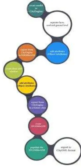
The workflows of the two procedures are presented in Fig.1 and Fig. 2 respectively:
Figure 1: Workflow of the 1st methodology
Figure 2: Workflow of the 2nd methodology The International Archives of the Photogrammetry, Remote Sensing and Spatial Information Sciences, Volume XLII-2/W2, 2016
Based on the results of the two above mentioned approaches, a comparison between the procedures and the generated CityGML models is performed and resented. The comparison focuses on aspects such as: technical background knowledge, time-efficiency, comprehensiveness of the model in terms of semantics and geometry, possibilities of further exploitat ion of the model, availability of the software and data shown, limits and constraints of the procedures etc. The comparison is based on a ranking order of the involved attributes, and when completed, the optimal procedure is presented.
3. CAS E S TUDY
3.1 Model generation with Trimble S ketchUp and FME
The generated CityGM L model consists of two concrete, although relevant between each other procedures: the design of the 3D building model in Trimble SketchUp 2016 and the transformation of the designed building model into a CityGML building model with the use of FM E Software. For the specific model, LoD 3 was achieved as maximum Level of Detail. For the CityGM L M odel, the following methodological steps have been elaborated.
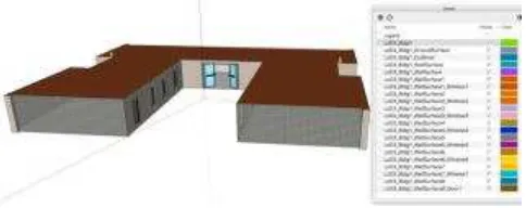
3.1.1 Modelling in Trimble S ke tchUp: Firstly, during the design of the model, specific characteristics had to be considered to ensure its compatibility for the transformation to a CityGML model. Specifically, after the design of the model completes, the user creates the layers that correspond to each object in the model. In order to achieve the highest possible time-efficiency, labels that fully describe the objects that are also included in the CityGM L standard should be assigned. The format of these labels include the Level of Detail, the specific Building and the feature types, e.g. LoD3_Bldg1_WallSurface1_Window 1, LoD3_Bldg1_RoofSurface, etc. The labels could include less information, although the aim of this methodology is to present an optimal way for creating a CityGM L model that may be consisted of more than one features. As a result, the user is able to identify easily and quickly every object in the model. The second major step in modeling with Trimble SketchUp is the connection of every boundary surface with its Openings (Door, Windows). The latter is achieved, by distinguishing each and every WallSurface that includes an opening and creating two new layers that include the Surface and the Opening(s) (Window, Door) separately, as shown in Figure 3. M oreover, a layer named LoD3_Bldg1, is created in order to store all the geometry that is generated by the SketchUp software that is specifically used for design purposes and is not related with the model’s correct CityGM L transformation in the next stage.
Figure 3: Assignment of Layers in Trimble SketchUp
The following table, presents the matching, between the SketchUp layers naming and the features in CityGM L Standard.
Table 1: Co-relation between layers and CityGM L Features
Also, in order to achieve the greatest realism possible, textures from the appearance of the building in reality were assigned to the designed model, as shown in figure 4.
Finally, as soon as the model is completed, Trimble SketchUp, provides the ability of Geolocation. Although, it is achievable only in the Coordination System of Google Earth, this is an important information that the user must consider during the transformation to a CityGM L M odel through the FM E on later stages.
Figure 4: Exterior WallSurface of the designed building
3.1.2 Transformation via FME S oftware: The transformation of the designed Building model into a CityGM L Building M odel with the use of FM E Software is described as follows. The workbench presented, is able to transform every SketchUp model, up to LoD 3, into a CityGM L Building M odel. M ost of the procedure is executed without any outer intervention from the user, although there are certain modifications the user shall apply, depending on the imported SketchUp model.
Firstly, the user is able to change the Coordination system of Google Earth, to the system that fits the purposes of the model, through the Repr ojector transformer.
Secondly, in order to confirm the correctness of the generated CityGM L Building model, the workbench executes tests, that remove all the unnecessary geometries that might have been created during the design in Trimble SketchUp and the CityGML Standard does not require them.
As soon as the coordination system and the model’s geometry is accurate, the transformer AttributeFilter (figure 5) is being used and the user adds the attributes labelled exactly as the layers in SketchUp. By the time the layers are added, the user can manually connect every attribute in the AttributeFilter Transformer, with the corresponding CityGM L Feature Type. In case the model includes Openings, it is crucial that the user connects the Surface, not only with the specific CityGML Feature Type, but also with the FeatureM erger (Supplier) Transformer. This is necessary, in order to identify the semantic hierarchy between the surfaces and the openings.
SketchUp Layer Naming CityGML Featur e Type The International Archives of the Photogrammetry, Remote Sensing and Spatial Information Sciences, Volume XLII-2/W2, 2016
Figure 5: The AttributeFilter Transformer
Then, by utilizing the Attr ibuteCr eator and the CityGMLGeometr ySetter transformer, the user is able to define the attributes as well as the geometries and their Levels of Detail, depending on the scope of the model.
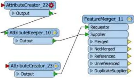
If the model includes openings, the workbench executes a routine that assures that each opening belongs to the appropriate surface, based on the CityGM L Standard, as shown in figure 6. The FeatureM erger Transformer is consisted of the Requestor and the Supplier. In order to merge the assigned WallSurface with its Opening, the user creates two tables in both AttributeCreator Transformers. The tables have the Title: Join and the same Value numbered e.g as1, 2, etc. Every FeatureM erger hase the same Title, but never the same Value.
Figure 6: Connection between the Openings and theSurfaces
The CityGM L feature types are already inside the Workbench, so the user will be able to choose the necessary ones for the model. Lastly, it is possible to add attributes such as class, function,
Attr ibuteCr eator transformer that is connected with the Building feature, as shown in figure 8.
Figure 7: Addition of attributes in the model
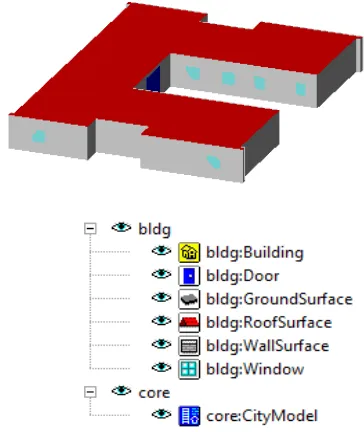
As soon as the workbench is finalized and the user runs the routine, by right clicking a random feature ty pe, it is possible to view the Building in the FM E Data Inspector, as shown in figure 8.
Figure 8: Visualisation in FM E Data Inspector
3.2 Model's generation with ES RI's CityEngine and managing with 3DCities Project for ArcGIS
The following methodology consists of two clearly separated but fully compatible steps. Firstly, the creation of the model in ESRI's CityEngine and then the semantic enrichment and the transformation to a CityGM L model by using the tools of 3DCities Project for ArcGIS. A detailed guideline of these procedure is further explained.
3.2.1 Modeling in CityEngine: the first step to create a model in the CityEngine environment is to import the building footprint (figure 9). All the necessary information was stored to the Object Attributes fields, according to the attributes that the Building feature class of the 3DCIM determines, as shown in figure 10. The International Archives of the Photogrammetry, Remote Sensing and Spatial Information Sciences, Volume XLII-2/W2, 2016
Figure 10: The attributes of the building footprint
Since CityEngine incorporates the Procedural modeling approach for creating 3D models, a rule is necessary. The rule repetitively applied, will create the facade of the model. At first the rule is used to extrude the building model t o the appropriate height value and then the faces of the model are separated, as shown in figure 11. To each face of the building the appropriate attributes are stored in the Object Attributes field according to the fields of the BuildingShellPar ts feature class of the 3DCIM , as presented in figure 12. At this point, also, the roof and the ground surface of the building are diverged from the wall surfaces.
Figure 11: The extruded model of the building with separated surfaces
Figure 12: The attributes rendered to the ground, the roof and the wall surfaces
After the extrusion of the model and the assignment of the required thematic and semantic information, the surfaces (the wall surfaces, the roof and the ground level) are exported in shapefile format.
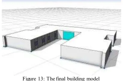
In order to reach the LoD3 of the building model the designing of the openings (windows and door) is required. The formation of the rule in the CityEngine leads to the creation of the model. The final model is presented in figure 13.
Figure 13: The final building model
At this point the Object attributes of both the window and the door, are enriched, as previously done for the wall surfaces, the roof and the ground floor, as shown in figure 14.
Figure 14: Left the attributes of the door. Right the attributes of the windows
Next step is the export of the Openings as shapefile format. It is important to mention that during the export process neither the wall surfaces and the model nor the openings, missed information.
3.2.1 S emantic Enrichment using 3DCities Project: After the creation of the model and the export of the data from CityEngine, the 3DCities Project tools were used. Firstly, the geodatabase of the 3DCIM was created in order to semantically enrich the model. In this case the feature classes Building, BuildingShellParts, BuildingInteriorStructures are included in the geodatabase. The geodatabase created for this case study is shown in figure 15.
In the Building feature class the 2D footprint of the building is in the BuildingShellPar t each wall surface, the roof and the ground level are separately loaded and the windows and the door are in the BuildingInter ior Str uctur e. The index of each feature class is presented below (figure 16).
Figure 16: The index of the Building, the BuildindShellPart and the BuildingInteriorStructure
Final step of the methodology is to export the 3DCIM File Geodatabase to CityGM L format. This is an automatic procedure since the ETL tools of the 3DCitites Project incorporate the FME Workbench (Feature M anipulation Engine, Safe Software) and its functions. The correct match of the data is very significant at this step, in order to ensure a lossless transformation. The final CityGM L model is being inspected in the FZKViewer environment. The final model is presented below (figure 17). The International Archives of the Photogrammetry, Remote Sensing and Spatial Information Sciences, Volume XLII-2/W2, 2016
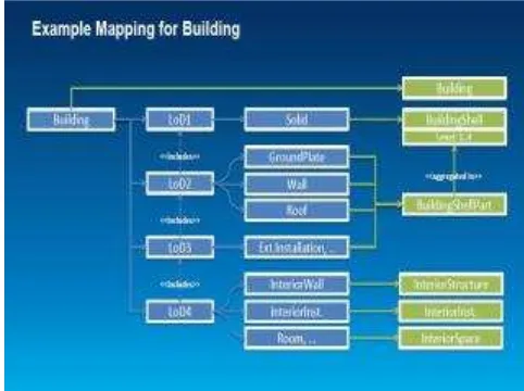
As it is concluded after evaluating the final model, the only deviation from the CityGM L standard is that the wall surfaces are represented as M ultisurfaces in LoD2 instead of LoD3. In figure 18 the structure of the 3DCIM CityGM L model is shown.
Figure 18: The structure of the 3DCIM (Arcgis.com, 2014)
4. EVALUATION OF THE METHODOLOGIES
4.1 Georeference
1st M ethodology: In Trimble SketchUp there are limitations regarding the modeling in regard to data coordinates with sp ecific reference system. However, the georeference of a model is partially solved utilizing the Google Earth Geolocation plugin. Additionally, the FM E provides the ability to re-project the reference system of the SketchUp file to the reference system that fits the purposes of the user.
2nd M ethodology: The import of a georeferenced building footprint in the CityEngine successfully addresses the georeference issue. M oreover, CityEngine supports the reference system used in this case study and as a result the model has the correct georeference. In the 3DCities Project, the specific reference system is also supported, and consequently the georeference is preserved.
4.2 User friendliness
1st M ethodology: Trimble SketchUp is a user-friendly modeling tool. However, if the aim of the project is to create a CityGML M odel, the user has to be familiar with the basic structure and principles of the CityGM L Standard, especially for a LoD 4 model, since some features such as the boundary surfaces become more complicated. The FM E Desktop Manager requires several trials since it provides numerous conversion options are. M oreover, the user must be deeply aware of the CityGML structure, in order to generate a semantically, geometrically and topologically concrete CityGM L M odel.
2nd M ethodology: The modeling process in CityEngine is standard since it simulates a simple form of programming language. The user can intervene in the ruling in order to create a model. However, it is important to be familiar with the principles of CityGM L, in case this format is the desirable outcome of the transformation. The 3DCIM toolbox is incorporated in the ArcGIS environment, which is a popular GIS software.
Nevertheless, the comprehension of the information model’s structure is advisable.
4.3 Ability of Expansion
1st M ethodology: The transition from a LoD1 to a LoD3 M odel has a low level of difficulty. In order though to create a LoD 4 M odel, a start-over is required if the interior is added complicating the new model, both geometrically and topologically. However, Trimble SketchUp seems to be a solid tool for various modeling projects in terms of realism and in presenting different aspects of the city. As soon as the model is enriched in the Trimble SketchUp software, the FM E is able to convert each and every additional information to the gml format. However, the user must edit the workbench based on the CityGM L M odel that wants to generate, a procedure that requires a certain level of knowledge of the FM E conversion tools.
2nd M ethodology: Creating a detailed building model in CityEngine has a low level of difficulty. However, an even more detailed model in Lod4, with information about the interior structures, demands appropriate data and greater effort when creating the procedural rule. The 3DCities Project offers a standardized information model in order to serve a wide range of applications. Although FM E tools are incorporated, an adequate knowledge of FM E and its functions is required in order to customize or further expand its information model.
4.4 Cost
1st M ethodology: Trimble SketchUp is a software commercially available to the public. The FM E Desktop M anager is commercially available to the public as well, however it offers multiple trial periods and special licenses. In terms of cost of time, the modeling process requires some experience in order to become familiar with the tools of Trimble SketchUp. A complete Building in LoD 3 can be modelled within a day. However, the FM E Workbench offers unlimited capabilities of converting the model. As a result, in case there is not a previous workbench to work upon a generous amount of time is required in order to figure out the optimal way for a CityGM L conversion.
2nd M ethodology: The CityEngine and the ArcGIS are ESRI’s software and are both commercially available, also offering trial periods and academic licenses. The time invested to complete the particular project is considered rather short. M odeling in the CityEngine is fast since it is characterized by repetitiveness, and so it does not demand much time. Once you grasp how the rules are formed the modeling process is quick. In the ArcGIS environment, the data are loaded to the relevant feature classes in the 3DCitiesProject quickly and since the transformation to the CityGM L format is fully automatic, the final model is generated in a short time.
4.5 Automatism of the Procedure
1st M ethodology: The modeling may be characterized as a manual process, although there are various tools that enhance the automatism of specific modeling steps, such as the floors or the installations. Inside the FM E, the conversion procedure can be described as a semi-automatic one. As soon as the workbench is created, the user has to interfere in specific parts of the procedure to customize the transformers based on the purposes of the project.
2nd M ethodology: In CityEngine, the syntax of the rule and the assignment of the necessary attributes to create the model can be characterized as manual. Nevertheless, there are functions that The International Archives of the Photogrammetry, Remote Sensing and Spatial Information Sciences, Volume XLII-2/W2, 2016
are automatic and fulfill the modeling process. As soon as, the data is loaded in the 3DCitiesProject, the transformation to CityGM L format is characterized as an automatic process.
4.6 Visualization
1st M ethodology: In terms of visualization, Trimble SketchUp provides great modeling tools that enhance the realism of the model, such as shadows, fog etc. The online warehouse is a great source of various components and commands such as the ‘’section plane’’ that allows for the observation of the model’s interior areas. The FM E provides the ability to visualize the model at every stage of the conversion procedure. This is a particularly useful feature, since it provides a great help for the detection of errors and malfunctions. M oreover, the FME Desktop M anager is able to visualize the generated CityGML model. The textures and the semantic information of the model are also visible through FM E Desktop M anager.
2nd M ethodology: CityEngine offers the ability to repetitively produce building models with high visual quality. It is a software designed for 3D modeling and the assignment of the facade’s details results to the creation of a truly realistic model. The information model of the 3D Cities template supports appearance in order to produce a realistic model. As a result all the information, attributes, geometry and appearance of the procedurally generated model is preserved and may be successfully loaded in the 3DCIM file geodatabase.
4.7 Accuracy of the Model
1st M ethodology: Trimble SketchUp is a software mainly designed for architectural use, providing a great level of accuracy during the modeling. The length and width of the objects are calculated with an accuracy of at least two decimals, while the three axis that exist in the model support the successful orientation of the model’s surfaces. However, the lack of a highly accurate geolocation can be an issue for specific study field areas. The FM E software provides accuracy in the semantic and topological aspects of the model. The user is able to add specific attributes to every CityGM L object, as well as determine their geometry, feature role and level of detail.
2nd M ethodology: M odeling in CityEngine is accurate, since 3D modeling is the main purpose for its development. The rules for the creation of the model in CityEngine are based on precise data, and so the final model is geometrically correct. The 3DCities Project is used for the semantic enrichment of the procedural model and the tools that it incorporates are fully capable of preserving the semantic and topological aspects of the information model and even enrich them.
4.8 Data S tructure
1st M ethodology: The generation of a model, can be achieved through various modeling methods depending on the project. When the model is generated, in order to achieve a successful conversion to a gml file based on the CityGml Standard, the data must be structured in a specific form. The more parts the model is consisted of, the higher the level of difficulty to structure the data, since it is a completely manual process. The creation of the workbench in FM E, requires a certain structure of the transformers and the parameters being used. As soon as the workbench is completed, the data in terms of identification match the data in the Trimble SketchUp, a procedure that is manually executed by the user.
2nd M ethodology: CityEngine provided different options in developing a 3D model. The higher the complexity and the information of the model, the more difficult is the modeling and stronger the need for better structure. M oreover, the data structure needs to be compatible with the structure of the Information M odel of the 3DCities Project. In order to achieve interoperability, the compliance to the structure of the 3DCIM and consequently to the CityGM L Standard is vital.
5. CONCLUS IONS AND FUTURE RES EARCH
Based on the above evaluation of the two methodologies, the following conclusions can be obtained: the model generated via the first methodology is visually concrete and realistic. The limitless available components render Trimble SketchUp as a solid tool for complicated visual projects that include more information than the surfaces of the building. M oreover, the simple modeling procedure produces precise results in a short time. The expansion of the model, by using various different CityGM L modules is also available. The FM E, is a transformation tool with a wide range of attributes and semantic information that can be implemented to the model. Hence, despite Trimble SketchUp is limited in terms of processing semantical information, this disadvantage is adequately covered by the FM E Workbench capabilities. In case that the model is consisted of significantly more buildings and other CityGML modules, the transformation in FM E requires respectively more effort and time. Finally, the limited abilities for geolocation do not recommend the use of the generated model for land use and cadastral purposes. To sum up, the first methodology presents a procedure that generates a CityGM L model that supports every function of the CityGM L Standard, in terms of the Building M odule. The FM E allows the user, to edit the parameters and the information that are being transformed and is fully compatible with the semantic aspects of the CityGM L Standard. The generated model can be successfully used in the wider field of the 3D Smart Cities’ simulation, such as architecture, energy, environment and urban planning.
The CityEngine mainly focusses on the 3D modelling of the city fabric, and lacks semantic information. The export options offered by this software are not able to preserve the semantic information incorporated to the model. The template solution for ArcGIS, the 3DCities Project, may be exploited for the semantic enrichment of the model. Potential interoperability issues may be overcome if the initial data are structured based on the specifications defined by the 3DCIM and consequent ly the CityGM L. On the other hand, the creation of the model in CityEngine environment was neither time-consuming nor cumbersome, since no particular programming skills are needed and the final model is efficient in terms of appearance and realistic visualization. As far as the 3D Cities Project is concerned, it is a collection of geoprocessing tools, base layers, sample projects and information model, very useful in a wide range of applications. The information model, and particularly the geodatabase, serve many different purposes. The 3DCIM file geodatabase contains defined feature classes with specific attributes and relations between them. Consequently, it is important the structure of the geodatabase to be thoroughly investigated in order to be populated with the appropriate data, according to the specifications defined. Additionally, incorporating the FM E software, which has strong capabilities to translate and transform data, it is possible to automatically transform the data stored in the 3DCIM file geodatabase to a CityGM L compatible format. The semantic enrichment of the initial building model and the transformation to CityGM L were successfully completed, harmonizing with the restrictions and the The International Archives of the Photogrammetry, Remote Sensing and Spatial Information Sciences, Volume XLII-2/W2, 2016
structure of the 3DCIM and the CityGM L, thus achieving interoperability and no losses of data. The only problem pointed out from this procedure relates to the rendering of the surfaces in LoD2 instead of LoD3.
With regard to future research, the Building module of CityGML, has been thoroughly investigated and successfully generated in various LoDs. An interesting field for further research is exploring the other CityGM L M odules, such as the Transportation Complex, the Bridge M odule, the Land Use and the City Furniture in an effort of generating CityGM L model with multiple modules that uniquely interact with each other. Within this context, a comparison with the BIM M odeling methodology and the adequacy of the two methodologies in terms of semantics would also be worth investigating. M oreover, another challenge is to convert the semi-automatic procedure of the FME Transformation into a fully -automatic procedure where the user will not have to manually intervene in the workbench. Finally, since the assignment of the layer in Trimble SketchUp can be described as a challenging task, the creation of an external plug-in that semi-automatically assigns the layers to the correspondplug-ing objects might be proven as a solid tool to enhance the modeling procedure. Concerning the 3DCities Project, addressing the malfunction of the geometries in the appropriate level of detail needs to be also investigated. Another advantage of using the 3DCities Project is its potential application to land use and property related issues, by storing relevant information to the geodatabase incorporated, leading to the development of an organized way of maintaining records.
REFERENCES
Benner, J., Geiger, A., Gr̈ger, G., Ḧfele, K. H., & L̈wner, M. O. 2013. Enhanced LoD concepts for virtual 3D city models. ISPRS Annals of the Photogr ammetr y, Remote Sensing and Spatial Infor mation Sciences, 2, W1.
Breunig, M ., & Zlatanova, S., 2011. 3D geo-database research: Retrospective and future directions. Computer s & Geosciences, 37(7), pp.791-803.
Brown, G., Nagel, C., Zlatanova, S., & Kolbe, T. H., 2013. M odelling 3D topographic space against indoor navigation requirements. In Pr ogr ess and New Tr ends in 3D Geoinfor mation Sciences pp. 1-22. Springer Berlin Heidelberg.
deLaat, R., & van Berlo, L., 2011. Integration of BIM and GIS: The development of the CityGM L GeoBIM extension. In Advances in 3D Geo-Infor mation Sciences pp. 211-225. Springer Berlin Heidelberg
Diakité, A.A, Damiand, G. and Gesquière, G., 2014. Automatic Semantic Labelling of 3D Buildings Based on Geometric and Topological Information. In Pr oceedings of 9th Inter national 3D GeoInfo Confer ence (3D GeoInfo), Nov. 2014, Dubai. United Arab Emirates. Karlsruhe Institute of Technology, 3DGeoInfo conference proceedings series.
Dimopoulou, E., & Elia, E., 2012. Legal aspects of 3D property rights, restrictions and responsibilities in Greece and Cyprus. In Pr oceedings of the 3r d Inter national Wor kshop on 3D Ca dastr es, Developments and Practices pp. 25-26.
Dimopoulou, E., Tsiliakou, E., Kosti, V., Floros, G., and Labropoulos, T., 2014. Investigating Integration Possibilities between 3D M odeling Techniques. In Pr oceedings of 9th Inter national 3D GeoInfo Confer ence, Nov. 2014, Dubai. United Arab Emirates.
D̈llner, J., Baumann, K., Buchholz, H., 2006. Virtual 3D City M odels as Foundation of Com- plex Urban Information Spaces. In: Schrenk, M . (Ed.), Proc. 1st inter national confer ence on Ur ban Planning and Spatial Development in the Infor mation Society (REAL CORP). CORP - Competence Center of Urban and Regional, Planning, pp. 107-112.
Donkers, S., 2013. Automatic Generation of CityGM L LoD3 Building M odels from IFC M odels. M Sc thesis, Delft University of Technology, Department of GIS Technology, OTB Research Institute for the Built Environment
El-M ekawy, M ., 2010. Integrating BIM and GIS for 3D City M odelling: The Case of IFC and CityGM L. Licentiate Thesis, KTH, Stockholm, Sweden
El-M ekawy, M ., Östman, A., & Shahzad, K., 2011. Towards interoperating cityGM L and IFC building models: a unified model based approach. In Advances in 3D Geo-Infor mation Sciences pp. 73-93. Springer Berlin Heidelberg.
Floros, G., Tsiliakou, E., Kitsakis, D., Pispidikis, I., Dimopoulou, E., 2015. Investigating Semantic Functionality of 3d Geometry for Land Administration. In Pr oceedings of 10th Joint Inter national 3D GeoInfo Confer ence, Oct. 2015, Kuala Lumpur, M alaysia.
Gr̈ger, G., Kolbe, T., & Czerwinski, A., 2007. Candidate OpenGIS® CityGM L Implementation Specification (City Geography M arkup Language). Open Geospatial Consortium Inc, OGC.
Gr̈ger, G., Pl̈mer, L., 2012. CityGM L – Interoperable semantic 3D city models. ISPRS Jour nal of Photogr ammetr y and Remote Sensing 71 (2012) 12–33
Isikdag, U., Zlatanova. S., 2009. Towards Defining a Framework for Automatic Generation of Buildings in CityGM L using Building Information M odels. In: Lee J. and Zlatanova, S. (Eds.) 3D Geoinfor mation Sciences, pp.79-96, Springer Berlin Heidelberg.
Kolbe, T.H., 2009. Representing and Exchanging 3D City M odels with CityGM L. Proceedings of the 3rd International Workshop on 3D Geo-Information, Seoul, Korea. Lectur es in Geoinfor mation and Car togr aphy, Springer Verlag.
Kolbe, T.H., 2008. Representing and Exchanging 3D City M odels with CityGM L. In: Lee, J., Zlatanova, S. (Eds.), 3D Geo-infor mation Sciences. Spr inger, Berlin, pp.15–31.
M uller, P., Wonka, P., Haegler, S., Ulmer, A., & Gool, L.V., 2006. Procedural M odeling of Buildings. ACM Tr ansactions on Gr aphics, 25(3), pp. 614-23.
Sadidi, J., Talebzadeh, M ., Rezaian, H., Zeaiean, P., 2015. Designing 3D Semantic M odel in LOD4 to Simulate Building Utility Network, Indian Jour nal of Science and Technology, Vol. 8(16), July 2015
Stadler, A., Kolbe, T. H. 2007. Spatio-semantic coherence in the integration of 3D city models. In Pr oceedings of the 5th Inter national Symposium on Spatial Data Quality, Enschede.
Zlatanova, S., Stoter, J., Isikdag, U., 2012. Standards for exchange and storage of 3D information: Challenges and opportunities for emergency response. In Pr oceedings of the Four th Inter national Confer ence on Car togr aphy and GIS, Albena, Bulgaria, pp. 17-28.
M üller, P., Wonka, P., Haegler, S., Ulmer, A., and Van Gool, L., 2006. Procedural modeling of buildings. ACM Trans. Graph., vol. 25, no. 3, p. 614.
Zhu, Q., Zhao, J., Du, Z., Zhang, Y., Xu, W., Xie, X., & Wang, T., 2011. Towards semantic 3D city modeling and visual explorations. In Advances in 3D Geo-Infor mation Sciences (pp. 275-294). Springer Berlin Heidelberg.
ESRI, (2014). Getting started with 3D Cities. https://github.com/Esri/3d-cities-template
ESRI, (2014). 3D Cities Information M odel Overview. https://github.com/Esri/3d-cities-template