Towards Rational Design Method for Strengthening of Concrete
Structures by External Bonding
Ueda, T.1, Zhang, D.1 and Furuuchi, H.1
Abstract: Many infrastructures need to be repaired or strengthened due to various reasons, such as unexpected deterioration and changes in performance requirement. This paper presents the following recent achievements by the authors’ group on design method for flexural strengthening of concrete structures by external bonding; (i) fracture characteristics of interface between substrate concrete and cementitious overlay, (ii) crack spacing of flexural strengthened beams, which affects debonding strength, (iii) strengths of intermediate crack (IC) debonding and end peeling, (iv) strength of concrete cover separation, and (v) effectiveness of strengthening by external bonding. A unified approach for flexural strengthening by steel plate, fiber reinforced polymer laminate and cementitious overlay, for both intermediate crack (IC) debonding, including end peeling, and concrete cover separation is presented with consideration of crack spacing in the strengthened members. Appropriate interfacial roughness to achieve efficient interface bond property is clarified and the concept of effectiveness of strengthening is proposed for better strengthening design.
Keywords: Strengthening, concrete structure, external bonding, overlay, steel plate, FRP laminate, IC debonding, concrete cover separation.
Introduction
We have been constructing abundant infrastructures to make the people’s life of higher quality. Unfor -tunately, it is the fact that many infrastructures need to be repaired or strengthened due to the various reasons, such as unexpected deterioration and changes in performance requirement. Repairing and strengthening can extend the service life of infrastructures, so that not only the cost but also the resources and energy can be saved, meaning that it would contribute to the global sustainability.
One of the typical repair/strengthening methods for concrete structure is strengthening by external bonding. There are three types of externally bonded materials, which are tension reinforcement for con-crete, as follows:
Steel plate FRP laminate Cementitious overlay
Both steel and FRP are good tension materials. Before 1990s steel plate was most commonly used, while FRP laminate started to be applied more since the mid-1990s. Overlay with cementitious material needs tension material in it to make itself tension material. Overlay has been accepted well in practical cases. However, it is only considered as a repairing tool to enhance durability in most of the cases. Because of the above historical background, there are practical design guidelines available for external bonded steel plate and FRP laminate, but not for overlay. The most of design guidelines deal with steel plate cases and FRP laminate cases separately.
1 Lab of Engineering for Maintenance System, Faculty of Engineer-ing, Hokkaido University, Sapporo, JAPAN
Email: [email protected]
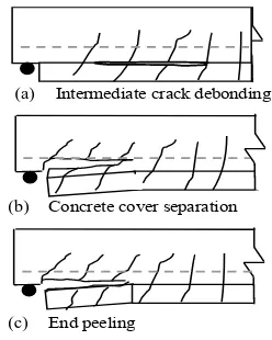
The primary technical issue common among exter-nally bonded steel plate, FRP laminate and cementi-tious overlay is debonding at interface between substrate concrete and bonded tension material. There are three types of debonding failure modes as follows (see Figure 1):
Intermediate crack (IC) debonding Concrete cover separation
End peeling
There are many studies on the above debonding mechanisms, especially in the case of externally bonded FRP laminate. However, no commonly accepted prediction method which can cover all of steel plate, FRP laminate and cementitious overlay has been established yet.
This paper presents the summary of the outcomes from series of studies done by the authors’ group on general design approach for strengthening concrete structures by external bonding, with emphasis on flexural strengthening and cementitious overlay. The following chapters include:
Figure 1. Three Types of Debonding Failure Modes (b)
(c)
Fracture characteristics of interface between sub-strate concrete and cementitious overlay
Crack spacing of flexural strengthened beams, which affects debonding strength
Strengths of IC debonding and end peeling Strength of concrete cover separation
Effectiveness of strengthening by external bond-ing
Fracture Characteristics of Interface
Bet-ween Substrate Concrete and
Cementi-tious Overlay [1]
Debonding at the interface between substrate con-crete and strengthening tension material in strengthened members are structural behavior. The debonding obviously depends on the interface frac-ture material properties, such as bond strength and fracture energy (in tension, shear and flexure). There are various parameters on the fracture properties, such as substrate concrete strength and roughness, adhesive strength and stiffness, and strength and stiffness of externally bonded material.
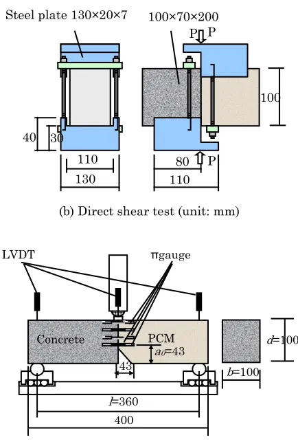
An experimental study was conducted on the fracture characteristics of polymer cementitious material (PCM)–substrate concrete interface. The parameters were interface roughness, Ra (see Figure
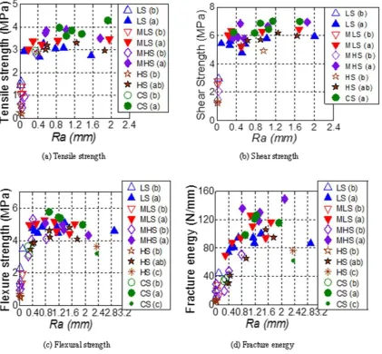
2), strength (4 levels; LS, MLS, MHS and HS) and coarse aggregate type (river gravel and crushed stone, CS) of substrate concrete. Splitting tensile, direct shear and three point bending tests were conducted to obtain bond tensile, shear and flexural strength respectively as shown in Figure 3. Fracture energy was also obtained through the three point bending test. The followings are the findings: (1)As shown in Figure 4, experimental results
indicate that interface bond strength and fracture energy without surface treatment are fairly low compared to those with surface treatment. The bond strength and fracture energy increase with interface roughness, Ra. The maximum bond
tensile and shear strength can be achieved with a small roughness Ra ≈ 0.4 mm. The maximum
bond flexural strength and mode I fracture energy can be reached with Ra≈ 1 mm.
Figure 2. Evaluation of Interface Roughness Ra
Figure 3. Tests for Bond Strength and Fracture Energy
(2)Regarding the single mode (Mode I or Mode II) bond and fracture properties as well as retrofitting costs, the Ra ≈1 mm (0.9 ≤ Ra≤1.1
mm) could be the optimum value of interface roughness for substrate concrete with normal size aggregate (10 ≤ Dmax ≤ 25 mm). The
corres-ponding optimum treatment depth with water jet treatment is 2-2.5 mm from the substrate surface.
(3)For any substrate concrete tested in this paper, the bond flexural failure happens at PCM-concrete interface adhesion layer when interface roughness is rather small and at concrete cohesi-on layer when the roughness is rather large. Both
f(x)
la
f
x
dx
l
R
0
(
)
1
l
Notch 100 x 7.5 x 7.5 (length x width x depth)
Concrete PCM 100
100 100 70
P
P
(a) Splitting tensile test (unit: mm)
130
Steel plate 130×20×7 100×70×200
100
110 80 110
40 30
(b) Direct shear test (unit: mm)
P
P P
Concrete PCM
l=360
a0=43 43
LVDT πgauge
d=100
b=100
400
the bond strength and fracture energy in the latter case are larger than those of the former case.
(4)The effect of aggregate type (crushed stone or river stone) on the interface bond strength and fracture energy is not distinct.
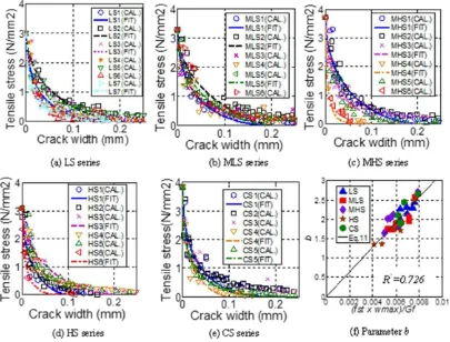
(5)The interface tension softening model taking into account effects of interfacial fracture energy, tensile strength and maximum crack width is presented based on the experimental results with modified J-integral method as follows:
b
st w
w
f
max
1
(1)where b is a non-dimensional material constant defined as a function of the bond tensile strength
fst, the bond fracture energy Gf and the maximum
crack width wmax:
f st
G
w
f
b
max (2)where α is determined to be 322 by fitting the equation to the calculated -w data. The maxi-mum crack width wmax is taken as 0.20 mm for
failure in the concrete cohesion layer (failure type a) or in the mixed layer between the concrete cohesion layer and the PCM adhesion layer (failure type ab) and as 0.10 mm for failure in the adhesion layer (failure type b) or in the PCM cohesion layer (failure type c). The calculated results by Equations 1 and 2 are compared with the tested results as shown in Figure 5.
Crack Spacing of Flexural Strengthened
Beams [2]
When the transferred bond stress within a distance to the next crack and the end of bonded strengthen-ing material is greater than the bond strength, IC debonding and end peeling would occur, leading to member failure (see section: Strengths of IC Debonding and End Peeling). Concrete cover separation also initiates at flexural or shear crack. The distance from the end of bonded strengthening material to the first crack is a controlling parameter for concrete cover separation strength (see section: Strength of Concrete Cover Separation).
A series of studies on average flexural crack spacing in concrete member strengthened by external bond-ing were conducted and the findbond-ings are as follows: (1)We show that current models of different
struc-tural codes for estimating average crack spacing of beams with multilayered reinforcement are inaccurate when applied to overlay strengthened RC beams with reinforcement layers, both in substrate concrete and overlay, although these two kinds of beams are similar in that reinfor-cement is multilayered. One of the main reasons for this mismatch is the different initiation loca-tion of tensile cracks between the substrate con-crete and overlay. However, substituting in the current structural codes only for the valid predict-tion of average crack spacing will not suffice, because the cracking mechanism is not clear. Moreover, existing empirical equations do not
apply to overlay-strengthened beam with reinfor-cement in overlay.
(2)We developed a crack spacing model by consi-dering the equilibrium and compatibility equati-ons of overlay-strengthened beam element. In case of cementitious overlay, flexural crack may initiate either in substrate concrete or overlay because the strength of overlay is usually higher than that of substrate concrete. Using the force equilibrium in effective substrate concrete and overlay, stabilized crack spacing can be calculated in the substrate concrete and overlay as follows (see Figure 6):
r bcm s bom
c o ot ct ct
cs
O O
E E A A f S
3
(3)
r bcm s bom
ot o c ct ot
os
O
O
A
E
E
A
f
S
3
(4)
where Or and Os denote the perimeter of
reinfor-cement in concrete and overlay respectively, Act
and Aot denote the effective tension area of
concrete and overlay. The peak bond stress τbcm or
τbom as shown in Figure 6(b) is calculated using
Figure 6. Element Analysis of Composite
for splitting failure withtransverse reinforcement (5)
25
transverse reinforcement (6)
) overlay, it will propagate to another layer due to the reduced stiffness of cracked section, therefore the stabilized crack spacing of overlay streng-thened composite Ss depends on the lesser of Scs average crack spacing of overlay strengthened beam under flexure load can be predicted as
tensile strains in the effective tension zone, k1 has
the maximum value of 1 in case of uniaxial load and minimum value of 0.5.
(4)For the case of FRP laminate or steel plate strengthening, the stabilized flexural crack spac-ing of strengthened RC beam is given by
r sc f StFRP
bond stress at the reinforcement-concrete inter-face and the steel/FRP-concrete interinter-face at the stabilized crack stage, which can be calculated as following: the predicted values of the average crack spacing based on the proposed model with a series of experimental investigations available in the literature that involved various types of beam elements (see Figure 7). The proposed models perform satisfactorily in measured response from the experimental work, both for steel bars or FRP grid-reinforced overlay and conventional RC beam with single or multilayered reinforcement. The proposed models also perform satisfactorily for steel plate and FRP laminate strengthening. Therefore, we can apply this model as a practical means of predicting the accurate average stabilized crack spacing in designing overlay-strengthened or conventional RC beams.
Strengths of IC Debonding and End
Peeling [3]
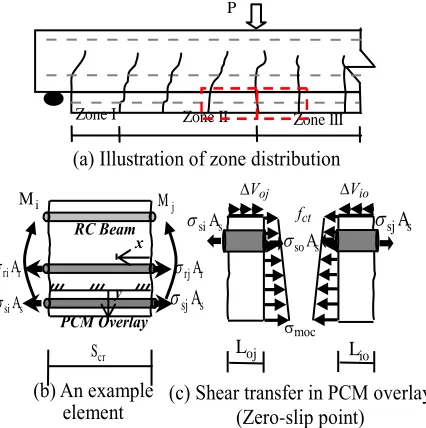
A study on intermediate crack (IC) debonding, including end peeling, in members with flexural strengthening by Polymer Cement Mortar (PCM) overlay was conducted to propose the prediction method for IC debonding in overlay end zone (zone I), shear flexure zone (zone II) and constant moment zone (zone III) as shown in Figure 8. The followings are the outcomes of the study:
(1)A simplified pure shear (pullout) specimen is analyzed first, and a bilinear bond-slip relation-ship of the PCM-concrete interface constitutive behavior is assumed. The theoretical maximum bond strength depends on the geometric proper-ties of the PCM overlay, material properproper-ties of the strengthening bars, and the fracture energy of the PCM-concrete interface that is a function of the substrate concrete properties. A unified equation for calculation of bond strength for any given bond length is then developed with reference to the current available models for steel plate and FRP sheet strengthening as follows:
max
(c) Free body diagram (a) Uniaxial tension on composite
Actf
Aotf
Figure 8. Illustration of Four-Point Bending Beam
Figure 9. Debonding Criteria
max
and cylinder compression strength of substrate concrete, respectively. According to experimental results, the mean value of Cτi and CGi can be
taken as 0.711 and 0.075 respectively.
(2)The tension-stiffening effect of the PCM to the strengthening bar and the moment gradient are two sources of generating shear stress along the PCM-concrete interface (see Figure 8). The shear force transfer mechanism of the PCM-concrete interface in the case of a beam subjected to bending load and the debonding process for an element with short or long bond length in different locations is analyzed with the stress and strain distribution along the interfaces.
(3)The theoretical bond strength indicates an upper limit on the transferred shear force for different applied loads. The debonding occurs when the transferred shear force is equal to or greater than the bond strength. The debonding strength can then be determined on the basis of the intersection point of two curves representing the transferred shear force and the bond strength of the PCM-concrete interface (see Figure 9). By comparing the debonding strength with the oretical flexure and shear strength of a given
strengthened beam, the peak load and failure mode can be determined according to the mini-mum strength of the strengthened beam.
(4)The reliability and accuracy of the proposed analytical procedure have been successfully very-fied by comparing the analytical and experi-mental values of the PCM-strengthened beam in a bending test database (see Figure 10).
Strength of Concrete Cover Separation [4]
An experimental study was conducted to develop the prediction analytical model for strength of concrete cover separation. The behaviors of PCM or HPFRCC overlay strengthened with steel bars or FRP grid failed by concrete cover separation were experi-mentally and analytically investigated first. Then the analytical model was extended to the case of concrete cover separation in members strengthened by externally bonded steel plate or FRP laminate. The main findings are as follows:
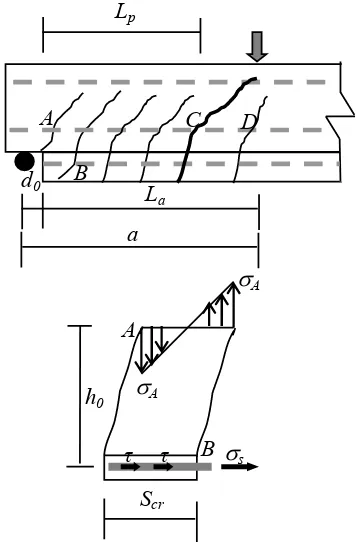
(1)The failure of the concrete cover separation was initiated by the formation of a crack at the edge of overlay caused by its abrupt termination. The crack was further propagated to the level of the tension reinforcement in the substrate concrete beam part and then progressed horizontally along the level of the steel reinforcement and the peak load is reached after the concrete cover separation until (i) the tension reinforcing bar yields or (ii) the entire shear span debonds. A simple analytical approach is developed based on the considerations in concrete near the reinforcing bar closest to the cut-off point of the overlay. The analysis, based on the tooth model (see Figure 11), consists of three stages; the determination of (i) local stress of substrate concrete at the lower face of the reinforcing bar, (ii) tensile stress of the reinforcement in overlay by assuming the monolithic composite action, and
Figure 11. Concrete Tooth Model
(iii) length of concrete cover separation corres-ponding to the peak load. Using this analytical approach, the peak load of overlay-strengthened beams with concrete cover separation can be predicted by the following equations.
p
r u dy
L
d
M
P
0
2
(20)
)
(
6
0s cr ct
r u g s s p
I
bS
f
M
x
d
A
h
L
(21)where Mru is the bending moment at the tension
reinforcement yielding of an unstrengthened (control) beam, and Lp is the concrete cover’s
debonding length at the failure load. d0 is the
distance between the support and the end of the overlay; h0 is the net concrete cover height
measured from the bottom side of the substrate concrete’s reinforcing bar to the center of the external reinforcement; b is the width of the beam; and As is the cross-sectional area of the
external reinforcement (either an FRP grid or a steel bar) inside the overlay; xg, ds and Is are the
neutral axis depth of the cracked section with strengthening, the effective depth of the external reinforcement and the transformed moment of inertia of the beam’s cracked cross-section in terms of the external reinforcement, respectively; and fctis the substrate concrete’s tensile strength.
(2)By comparing the predicted strength with the theoretical flexure and shear strength of a given
strengthened beam, the peak load and failure mode can be determined as the minimum strength of the strengthened beam among those strengths.
(3)The reliability and accuracy of the proposed analytical procedure have been verified by com-paring the analytical and experimental values of the overlay-strengthened beam provided in this study as well as the published literatures (see Figure 12).
Effectiveness of Strengthening by External
Bonding
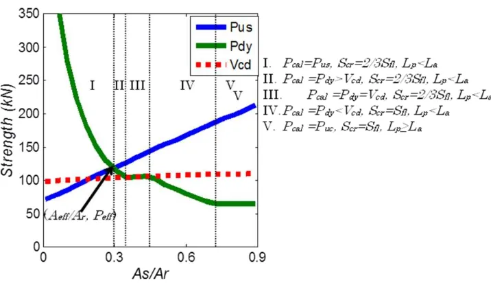
Based on the analytical model for concrete cover separation strength, a concept was presented to determine the efficient strengthening area and
Figure 12. Comparison Between Experimental and Analytical Peak Load
effecttive strengthening capacity by predicting the intersection point of the two curves representing the flexure strength (Pus) and debonding strength (Pdy),
both of which vary with the ratio of area of external and internal reinforcement As/Ar (see Figure 13 [4]).
Parametric studies clarify the effects of various parameters as follows; (i) when the strengthening reinforcement area is kept constant, bonds that are thicker and narrower have the better efficiency, (ii) the shorter distance between the end of the FRP laminate and the support has the better efficiency, (iii) when external reinforcement’s tensile strength is kept constant, smaller external reinforcement’s Young’s modulus has the better efficiency, and (iv) when external reinforcement’s Young’s modulus is kept constant, larger external reinforcement’s tensile strength has the better efficiency.
For the concrete cover separation the efficiency with FRP laminate and overlay strengthening is gene-rally better than that with steel plate strengthening.
Concluding Remarks
In order to develop a rational design approach for strengthening of concrete structures by external bonding, it is inevitable to develop prediction methods for various types of debonding strength. For flexural strengthening by steel plate, FRP lami-nate and cementitious overlay, a unified approach for both intermediate crack (IC) debonding, including end peeling, and concrete cover separation is pre-sented with consideration of crack spacing in streng-thened members. Appropriate interfacial roughness to achieve efficient interface bond property is clari-fied. The concept of effectiveness of strengthening is proposed for better strengthening design.
The followings are the remaining tasks for the ratio-nal design approach:
Develop the unified approach for IC debonding in steel plate, FRP laminate and cementitious over-lay strengthened members.
Develop the debonding criteria with considera-tion of normal stresses at interface.
Clarify the effects of chronological effects, such as effects of environmental actions and fatigue, on strengthened member performance.
Develop the design method for shear strengthen-ing.
Acknowledgement
This study is a part of the International Collabora-tive Research, “Life Cycle Prediction and Manage -ment of Concrete Structures” adopted by the Asia -Africa S & T Strategic Cooperation Promotion Program of Special Coordination Funds for Science and Technology of Japan’s Ministry of Education, Culture, Sports, Science and Technology. The authors also appreciate the financial aid provided by the Grant-in-Aid for Scientific Research (A) No. 22246058.
References
1. Zhang, D., Ueda, T. and Furuuchi, H., Fracture Mechanisms of Polymer Cement Mortar (PCM)- Concrete Interfaces, Journal of Engineering Mechanics, ASCE (to be printed).
2. Zhang, D., Ueda, T. and Furuuchi, H., Average Crack Spacing of Overlay-Strengthened RC Beams, Journal of Materials in Civil Engineer-ing, ASCE, 23(10), October 2011, pp. 1460-1472, DOI: 10.1061/(ASCE)MT.1943-5533. 0000316.
3. Zhang, D., Ueda, T. and Furuuchi, H., Inter-mediate Crack Debonding of Polymer Cement Mortar Overlay-Strengthened RC Beam, Journal of Materials in Civil Engineering, ASCE, 23(6), June 2011, pp. 857-865, DOI: 10.1061/(ASCE) MT.1943-5533.0000240.