CR-Form-v3
CHANGE REQUEST
IGM CR ?
rev-
Current version: OGC 07-031r2For HELP
on using this form, see bottom of this page or look at the pop-up text over the symbols.
Proposed change affects: AS Imp Spec X Best Practices Paper Other
Title: IGM change request - Not require application schema extensions
Source: Arliss Whiteside
Work item code: Date: 2009-01-19
Category: C
Use one of the following categories: F (Critical correction)
A (corresponds to a correction in an earlier release) B (Addition of feature),
C (Functional modification of feature) D (Editorial modification)
Reason for change: The current IGM specification requires specification and use of GML Application Schema extensions for each specific sensor model. However, a simpler alternative is to define and use XML document templates for each specific sensor model, instead of XML Schema extensions.
Summary of change: Extensively revise the current IGM specification to also allow use of XML document templates for each specific sensor model
Consequences if not approved:
Clauses affected: 6 through 9, D, igmImageGeometry.xsd,
igmObjectImageTransformationPackage.xsd, igmSensorCalibration.xsd, igmSensorParameterValuesPackage.xsd
Other specs Other core specifications Affected: Abstract specifications
Best Practices Papers
Supporting Doc.
Other comments: This change request is to the previously proposed, but not accepted, Image georeferencing metadata GML 3.2 Application Schema [OGC 07-031r2]. This change request is a change from the hard-typing of XML elements (normally used by GML), to also allow the soft-typing of several XML elements (often used by SensorML).
Status Disposition
Edit Clauses 6 through 9 as follows:
6 Image georeferencing metadata overview
1 Image georeferencing metadata
This GML Application Schema XML schema encodes parameter values for image
georeferencing coordinate transformations with associated parameter error statistics. This is done using two specializations of the CC_ ParameterValueGroup class (in OGC Abstract Specification Topic 2) and corresponding specializations of the gml:ParameterValueGroup XML element.
These georeferencing coordinate transformations can use many possible image geometry (or sensor) models that can be encoded using extensions of this Application Schema. However, each specific image geometry model requires an extension of this Application Schema as described in Annex D.A specific image geometry model extension is needed by each georeferencing coordinate transformation for an unrectified image. The
images in the Web Coverage Service (WCS) 1.1.1 [OGC 07-067r2] and Discussion Paper Web Coordinate Transformation (WCTS) [OGC 07-055r1]. However, each specific image geometry model needs specialization of this Application Schema, as described in Annex D.
This Application Schema also encodes point positions measured in one of more images and optional object coordinates, with associated position error statistics. These object points can be tie points, control points, and check points. A control or check point has a measured position with position error statistics in one or more images, and a known position with error statistics in some geodetic Coordinate Reference System (CRS). A tie point has a measured position with error statistics in two or more images, but not a known position in any geodetic CRS.
Error statistics are represented as variance-covariance matrices, representing both absolute and relative accuracies. These covariance matrices are used to represent correlations between the accuracies of different parameters, coordinates, and positions.
2 UML model packages
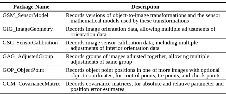
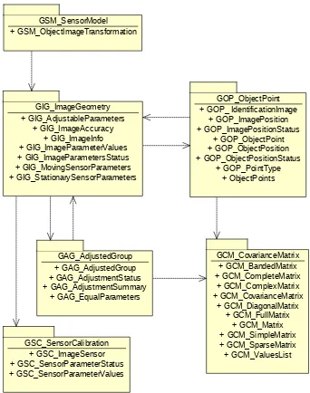
This Image georeferencing metadata GML Application Schema is specified in six parts, corresponding to six UML packages with six corresponding XML Schema Documents. The six UML packages are listed and briefly described in Table 1. The dependencies among these georeferencing metadata UML packages are shown in the Figure 1, together with the classes in each package.
Table 1 — Image georeferencing metadata UML model packages
Package Name Description
GSM_SensorModel Records versions of object-to-image transformations and the sensor mathematical models used by these transformations
GIG_ImageGeometry Records image orientation data, allowing multiple adjustments of orientation data
GSC_SensorCalibration Records image sensor calibration data, including multiple adjustments of interior orientation data
GAG_AdjustedGroup Records groups of images adjusted together, allowing multiple adjustments of same group
GOP_ObjectPoint Records object point positions in one of more images with optional object coordinates, for control points, tie points, and check points GCM_CovarianceMatrix Records covariance matrices, for absolute and relative parameter and
GIG_ImageGeometry + GIG_AdjustableParameters
+ GIG_ImageAccuracy + GIG_ImageInfo + GIG_ImageParameterValues + GIG_ImageParametersStatus + GIG_MovingSensorParameters + GIG_StationarySensorParameters
GSC_SensorCalibration + GSC_ImageSensor + GSC_SensorParameterStatus + GSC_SensorParameterValues
GOP_ObjectPoint + GOP_ IdentificationImage
+ GOP_ImagePosition + GOP_ImagePositionStatus
+ GOP_ObjectPoint + GOP_ObjectPosition + GOP_ObjectPositionStatus
+ GOP_PointType + ObjectPoints
GCM_CovarianceMatrix + GCM_BandedMatrix + GCM_CompleteMatrix
+ GCM_ComplexMatrix + GCM_CovarianceMatrix
+ GCM_DiagonalMatrix + GCM_FullMatrix
+ GCM_Matrix + GCM_SimpleMatrix + GCM_SparseMatrix + GCM_ValuesList GSM_SensorModel
+ GSM_ObjectImageTransformation
GAG_AdjustedGroup + GAG_AdjustedGroup + GAG_AdjustmentStatus + GAG_AdjustmentSummary
+ GAG_EqualParameters
Figure 1 — Image georeferencing metadata UML packages with dependencies
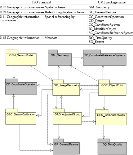
Table 2 — ISO/TC 211 UML model packages used
ISO Standard UML package name
19107 Geographic information — Spatial schema GM_Geometry 19109 Geographic information — Rules for application schema GF_GeneralFeature 19111 Geographic information — Spatial referencing by
coordinates CC_CoordinateOperationCD_Datum
CS_CoordinateSystem IO_IdentifiedObject
SC_CoordinateReferenceSystem
19115 Geographic information — Metadata DQ_DataQuality
EX_Extent
GIG_ImageGeometry
GSC_SensorCalibration
GOP_ObjectPoint
GCM_CovarianceMatrix GSM_SensorModel
CC_CoordinateOperation
GM_Geometry SC_CoordinateReferenceSystems
DQ_DataQuality GF_GeneralFeature
GAG_AdjustedGroup
Figure 2 — Image georeferencing metadata and ISO/TC 211 packages
3 GML application schema
features profiles. For ISO 19139, the profile is a subset of the ISO 19139 profile that is used by GML 3.2.1 (ISO 19136).
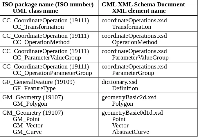
Most of the ISO/TC 211 classes used in the UML model are encoded by the GML 3.2.1 XML elements as listed in Table 3.
Table 3 — GML 3.2.1 elements encoding ISO classes
ISO package name (ISO number)
UML class name GML XML Schema Document XML element name
CC_CoordinateOperation (19111)
CC_Transformation coordinateOperations.xsdTransformation CC_CoordinateOperation (19111)
CC_OperationMethod coordinateOperations.xsdOperationMethod CC_CoordinateOperation (19111)
CC_ParameterValueGroup coordinateOperations.xsdParameterValueGroup CC_CoordinateOperation (19111)
CC_OperationParameterGroup coordinateOperations.xsdParameterGroup GF_GeneralFeature (19109)
GF_FeatureType dictionary.xsdDefinition GM_Geometry (19107)
GM_Polygon geometryBasic2d.xsdPolygon
GM_Geometry (19107) GM_Point
GM_Vector GM_Curve
geometryBasic0d1d.xsd Point
Vector
AbstractCurve
Each of these georeferencing metadata UML packages and corresponding XML Schema Documents is defined in subsequent clauses.
7 Sensor model
4 Introduction
The sensor model part of the Image georeferencing metadata GML Application Schema supports recording versions of object-to-image coordinate transformations and the (image geometry) sensor mathematical models used by these transformations. These object-to-image transformations are used for georeferencing coordinate transformations. These coordinate transformations can use many all possible image geometry (or sensor) models that can be encoded using extensions of this Application Schema. The parameter values used by these transformations are recorded in the image geometry and sensor calibration parts of this Application Schema.
5 UML model
CC_Transformation (from CC_CoordinateOperation)
<<Type>> (from CC_CoordinateOperation)CC_OperationMethod <<Type>>
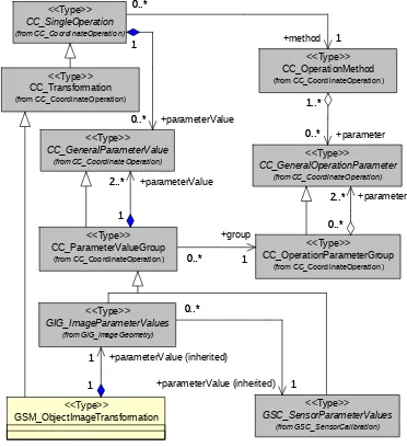
Figure 3 — GSM_SensorModel package UML class diagram
NOTE For simplicity, this diagram does not show the CC_ParameterValue concrete subclass of the CC_GeneralParameterValue abstract class, or the CC_Parameter concrete subclass of the
CC_GemeralParameter abstract class. Those concrete subclasses are not used in this document, but are used by extensions of this metadata for specific image sensor geometry models.
The GSM_SensorModel package specializes the CC_CoordinateOperation package in ISO 19111 [OGC 05-10308-015], by defining more-specific subclasses. By specializing the CC_CoordinateOperation package, the GSM_SensorModel package uses the existing ISO 19111 concepts and terms, for coordinate Transformations, Operation Methods, Operation Parameter Groups, etc.
Specifically, the GSM_ObjectImageTransformation class specializes the CC_Transformation class for image georeferencing object-to-image coordinate transformations. That new class uses the GIG_ImageParameterValues and
The CC_OperationMethod and CC_OperationParameterGroup classes have instances that are specialized for this use (specialized classes are not used).
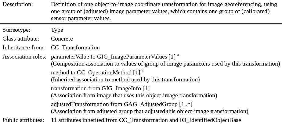
Table 4 — Defining elements of GSM_ObjectImageTransformation class
Description: Definition of one object-to-image coordinate transformation for image georeferencing, using one group of (adjusted) image parameter values, which contains one group of (calibrated) sensor parameter values.
Stereotype: Type Class attribute: Concrete
Inheritance from: CC_Transformation
Association roles: parameterValue to GIG_ImageParameterValues [1] a
(Composition association to values of group of image parameters used by this transformation) method to CC_OperationMethod [1] b
(Inherited association to method used by this transformation) transformation from GIG_ImageInfo [1]
(Association from image that uses this object-image transformation) adjustedTransformation from GAG_AdjustedGroup [1..*]
(Association from adjusted group that adjusted this object-image transformation) Public attributes: 11 attributes inherited from CC_Transformation and IO_IdentifiedObjectBase
a Association inherited through CC_Transformation, CC_SingleOperation, CC_GeneralPareameterValues, and CC_ParameterValueGroup.
b Association inherited through CC_Transformation and CC_SingleOperation.
NOTE These tables are using the table format used in ISO 19111 [OGC 05-10308-015].
6 XML encoding
The GSM_SensorModel UML package is encoded in the igmSensorModel.xsd XML Schema Document, which imports the coordinateOperations.xsd XML Schema Document from GML 3.2.1. The ISO 19111 classes used in the UML model are encoded by the GML 3.2.1 XML elements as listed in Table 3. The contents of the igmSensorModel.xsd XML Schema Document shall be as specified in the attached file.
EXAMPLE 1 An example XML fragment for an ObjectImageTransformation is:
<igm:ObjectImageTransformation gml:id="Transformation999.999">
<gml:identifier codeSpace="IGM">Transformation999.999</gml:identifier> <gml:scope>Domain of targetCRS</gml:scope>
<gml:operationVersion>0.0.0</gml:operationVersion>
<gml:sourceCRS xlink:href="urn:ogc:def:crs:EPSG:6.8:4979"/> <gml:targetCRS
xlink:href="urn:ogc:def:crs:OGC:0.0:ImageCRSpixelCenter:TBDimageID"/> <gml:method xlink:href="frameOperationMethodFile.xml"/>
<!-- =============================================== -->
<igm:parameterValue> <ImageParameterValues>
<igm:image xlink:href="imageInforFile999.xml#ImageInfo999"/>
<!-- Reference to ImageInfo element for this image -->
<igm:inGroup
to AdjustedGroup element for this adjusted set of image parameter values
-->
<igm:imageParametersStatus
codeSpace="../imageParametersStatusValues.xml">adjusted</igm:imageParamet ersStatus>
<igm:sensorParameterValues
xlink:href="sensorParametersFile999.999.xml#SensorParameters999.999"/>
<!-- Reference to SensorParameterValues element for this image -->
<igm:adjustableParameters
xlink:href="adjustableParametersFile999.xml#AdjustableParameters999"/>
<!-- Reference to AdjustableParameters element for this image -->
<!-- =============================================== -->
<gml:Point gml:id="Point999" srsName="LSR"> <gml:pos>999 999 999</gml:pos>
</gml:Point>
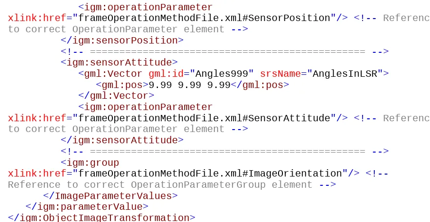
<igm:operationParameter
xlink:href="frameOperationMethodFile.xml#SensorPosition"/> <!-- Reference
to correct OperationParameter element -->
</igm:sensorPosition>
<!-- =============================================== -->
<igm:sensorAttitude>
<gml:Vector gml:id="Angles999" srsName="AnglesInLSR"> <gml:pos>9.99 9.99 9.99</gml:pos>
</gml:Vector>
<igm:operationParameter
xlink:href="frameOperationMethodFile.xml#SensorAttitude"/> <!-- Reference
to correct OperationParameter element -->
</igm:sensorAttitude>
<!-- =============================================== -->
<igm:group
xlink:href="frameOperationMethodFile.xml#ImageOrientation"/>
<!--Reference to correct OperationParameterGroup element -->
</ImageParameterValues> </igm:parameterValue>
</igm:ObjectImageTransformation>
NOTE An ObjectImageTransformation will often include inline encoding of the parameterValue element.
EXAMPLE 2 A longer example XML fragment for an ObjectImageTransformation is: <igm:ObjectImageTransformation gml:id="Transformation999.999">
<gml:identifier codeSpace="IGM">Transformation999.999</gml:identifier> <gml:scope>Domain of targetCRS</gml:scope>
<gml:operationVersion>0.0.0</gml:operationVersion>
<gml:sourceCRS xlink:href="urn:ogc:def:crs:EPSG:6.8:4979"/> <gml:targetCRS
xlink:href="urn:ogc:def:crs:OGC:0.0:ImageCRSpixelCenter:TBDimageID"/> <gml:method xlink:href="templateFrameOperationMethod1.xml"/>
<!-- =============================================== -->
<ImageParameterValues>
<igm:image xlink:href="imageInfoFile999.xml#ImageInfo999"/>
<!--Reference to ImageInfo element for this image -->
<igm:inGroup
xlink:href="adjustedGroupFile999.xml#IAdjustedGroup999"/> <!-- Reference to AdjustedGroup element for this adjusted set of image parameter values
-->
<igm:imageParametersStatus
codeSpace="../imageParametersStatusValues.xml">adjusted</igm:imageParamet ersStatus>
<igm:sensorParameterValues
xlink:href="sensorParametersFile999.999.xml#SensorParameters999.999"/>
<!-- Reference to SensorParameterValues element for this image -->
<igm:footprint>
<gml:Polygon srsName="urn:ogc:crs:EPSG:6.0:9999"
gml:id="Polygon999">
<gml:exterior> <gml:LinearRing>
<gml:pos>999 999</gml:pos> <gml:pos>999 999</gml:pos> <gml:pos>999 999</gml:pos> <gml:pos>999 999</gml:pos> </gml:LinearRing>
</gml:exterior>
<gml:interior> <!-- Repeated for each void in exterior ring -->
<gml:LinearRing>
<gml:pos>999 999</gml:pos> <gml:pos>999 999</gml:pos> <gml:pos>999 999</gml:pos> <gml:pos>999 999</gml:pos> </gml:LinearRing>
</gml:interior> </gml:Polygon> </igm:footprint>
<igm:adjustableParameters
xlink:href="adsjustableParametersFile999.xml#AdjustableParameters999"/>
<!-- Reference to AdjustableParameters element for this image -->
<!-- =============================================== -->
<igm:imageAccuracySummary> <igm:ImageAccuracySummary>
<igm:CE uom="m">99.9</igm:CE>
<igm:LE uom="m">99.9</igm:LE> <!-- Omit when not
stereoscopic image -->
<igm:horizontalShear uom="m">99.9</igm:horizontalShear> <!-- Omit when not applicable -->
<igm:verticalShear uom="m">99.9</igm:verticalShear>
<!--Omit when not stereoscopic image -->
</igm:ImageAccuracySummary> </igm:imageAccuracySummary>
<!-- =============================================== -->
<igm:sensorPosition>
<gml:Point gml:id="Point999" srsName="LSR"> <gml:pos>999 999 999</gml:pos>
<igm:operationParameter
xlink:href="frameOperationMethodFile.xml#SensorPosition"/> <!-- Reference
to correct OperationParameter element -->
</igm:sensorPosition>
<!-- =============================================== -->
<igm:sensorAttitude>
<gml:Vector gml:id="Angles999" srsName="AnglesInLSR"> <gml:pos>9.99 9.99 9.99</gml:pos>
</gml:Vector>
<igm:operationParameter
xlink:href="frameOperationMethodFile.xml#SensorAttitude"/> <!-- Reference
to correct OperationParameter element -->
</igm:sensorAttitude>
<!-- =============================================== -->
<igm:group
xlink:href="frameOperationMethodFile.xml#ImageOrientation"/>
<!--Reference to correct OperationParameterGroup element -->
</ImageParameterValues> </igm:parameterValue>
</igm:ObjectImageTransformation>
8 Image geometry
7 Introduction
The image geometry part of the Image georeferencing metadata GML Application Schema supports recording image (exterior) orientation parameter values, including image sensor position and attitude. This package supports multiple adjustments of this image orientation data. Most of these orientation parameter values are specific to each image collected by one image sensor, and usually must be adjusted for each image collected. These parameters can be for many possible image geometry (or sensor) models. that can be encoded using
extensions of this Application Schema.
8 UML model
GF_FeatureType
+ definition : CharacterString + typeName : LocalName
(from GF_GeneralFeature)
<<Metaclass>>
CC_ParameterValueGroup
(from CC_CoordinateOperation)
<<Type>>
A concrete subclass of one of these three abstract classes shall be specified for each specific sensor model
GIG_MovingSensorParameters + imagePixels : URI + imageCRS : URI + rows : PositveInteger + columns : PositiveInteger
<<Type>>
+ parameterStatus : GIG_ImageParametersStatus + imageAccuracySummary : GIG_ImageAccuracy
<<Type>> 1
1 1
+parameterValue (inherited) 1 0..* 1
EDITOR’S NOTE The GIG_ImageParameterValues, GIG_StationarySensorParameters. and GIG_MovingSensorParameters classes shown above were previously abstract, and should have had their class names in Italics. However, those classes are now changed to concrete classes, with class names not in Italics. The note box is now changed to read “A specialization of one of these three classes is needed for each specific sensor model”.
GIG_ImageParametersStatus
+ definition : CharacterString + typeName : LocalName
(from GF_GeneralFeature)
+ horizontalShear [0..1] : Length + verticalShear [0..1] : Length
<<DataType>> GIG_AdjustableParameters + parameters : Sequence<URI>
<<Type>>
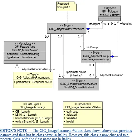
EDITOR’S NOTE The GIG_ImageParameterValues class shown above was previously abstract, and thus has its class name in Italics. However, this class is now changed to a concrete class, with the class name not in Italics.
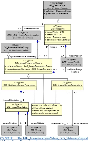
Figure 5 — GIG_ImageGeometry package UML class diagram, part 2
Part 1 of this UML class diagram shows how multiple versions of orientation parameter values can be recorded for each image. That is, multiple ImageParameterValues objects can be associated with the ImageInfo object for one image. As needed for different image types and purposes, different sensor models can be used by the multiple ImageParameterValues objects which are associated with the ImageInfo for one image. Similarly, different image parameters can be adjusted in different ImageParameterValues objects.
The ImageParameterValues abstract class records the parameter values for any sensor model, including the status of that group of parameter values. Each ImageParameterValues object also has an optional association to a Polygon giving the (approximate) footprint for the image using those parameter values.
The ImageParameterValues abstract class has StationaryImageParameters and Moving-ImageParameters abstract subclasses, which record parameter values common to all stationary or moving sensors. For a stationary sensor, these parameters are the sensor position coordinates, recorded using a GM_Point object, and the sensor attitude (rotation) parameters, recorded using a GM_Vector object. For a moving sensor, these parameters are the sensor path positions and the sensor attitude history, each recorded using a GM_Curve object (TBR). The sensor path and attitude history can be shared by multiple images collected in a strip, with each image specifying the collection time or range within this history.
The details specific to each specific sensor model are recorded as concrete
subclassesspecializations of the StationarySensorParameters and MovingSensorParameters abstract classes, which shall be specified in extensions of this Application Schema. These classes may share more classes for common aspects (also not shown here). Wherever relevant, these specific image geometry models should build upon and adapt ISO 19130 (Sensor data model for imagery and gridded data).
Part 2 of this UML class diagram shows that each ImageParameterValues object also has an association to one AdjustableParameters object that identifies which of the image and sensor parameters could have been adjusted by the associated AdjustedGroup. Each AdjustableParameters object can be associated from multiple ImageParameterValues objects which have the same set of adjustable parameters (as is common). Similarly, multiple ImageParameterValues objects can be associated with an AdjustedGroup object for one adjustment (or triangulation). Each AdjustedGroup object is associated to the ImageParameterValues objects that were adjusted or computed by this adjustment.
The ImageGeometry package specialises the GF_FeatureType package in ISO 19109, by defining more-specific subclasses. By defining the ImageInfo class as a feature collection, identification metadata is inherited and additional properties for recording needed metadata can be easily added. By defining the AdjustableParameters as a feature, identification metadata is inherited and additional properties for recording needed metadata can be easily added.
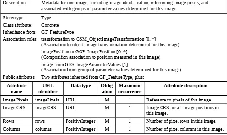
Table 5 — Defining elements of GIG_ImageInfo class
Description: Metadata for one image, including image identification, referencing image pixels, and associated with groups of parameter values determined for this image.
Stereotype: Type Class attribute: Concrete Inheritance from: GF_FeatureType
Association roles: transformation to GSM_ObjectImageTransformation [0..*]
(Association to object-image transformation determined for this image) imagePosition to GOP_ImagePosition [0..*]
(Composition association to position measured in this image) image from GIG_ImageParameterValues [1]
(Association from group of parameter values determined for this image) Public attributes: Two attributes inherited from GF_FeatureType, plus:
Attribute
name identifierUML Data type Obligation occurrenceMaximum Attribute description
Image Pixels imagePixels URI M 1 Reference to pixels of this image.
Image CRS imageCRS URI M 1 Image CRS for all image positions in
this image.
Rows rows PositiveInteger M 1 Number of pixel rows in this image.
Table 6 — Defining elements of GIG_ImageParameterValues class
Description: Group of parameter values for one adjustment of one image, including most exterior orientation parameters.
Stereotype: Type
Class attribute: ConcreteAbstract
Inheritance from: CC_ParameterValueGroup Association roles: image to GIG_ImageInfo [1]
(Association to the image using this group of image parameter values) parameterValue to GSC_SensorParameterValues [1] a
(Inherited association to the calibrated sensor parameter values used by this image parameter adjustment)
footprint to GM_Polygon [0..1]
(Composition association to approximate footprint of this image using this group of image parameter values)
adjustableParameters to GIG_AdjustableParameters [1} (Association to list of adjustable parameters in this group) group to CC_OperationParameterGroup [1] a
(Inherited association to operation parameter group for this group of image parameter values) adjustedImagePosition to GOP_ImagePosition [0..*]
(Composition association to image positions determined by this parameter group) inGroup to GAG_AdjustedGroup [0..1]
(Association to the adjustment group that produced this group of image parameter values) parameterValue from GSM_ObjectImageTransformation [1]
(Association from object to image transformation that uses this set of parameter values) Public attributes: No attributes inherited from CC_ParameterValueGroup, plus:
Attribute name UML
identifier Data type Obligation occurrenceMaximum Attribute description
Image parameter
status imageParameterStatus GIG_ImageParametersStatus M 1 Status of this group of image parameter values. Image accuracy
summary imageAccuracySummary GIG_ImageAccuracySummary M 1 Summary of positional accuracy ofthis image using this group of parameter values.
a Association inherited from CC_ParameterValueGroup.
Table 7 — Defining elements of GIG_MovingSensorParameters class
Description: Generic group of image parameter values for one image collected by a sensor which moved during image collection. A concrete subclass of this abstract class shall be specified for each specific moving image geometry (sensor) mathematical model, in an extension of this Image georeferencing metadata GML Application Schema.
Stereotype: Type
Class attribute: ConcreteAbstract
Inheritance from: GIG_ImageParameterValues Association roles: sensorPath to GM_Curve [1]
(Association to sensor path position coordinates during the collection period of one or more images)
sensorAttitudeHistory to GM_Curve (TBR) [1] a
(Association to sensor attitude “history” during the collection period of one or more images) Plus associations inherited from GIG_ImageParameterValuesclass
Public attributes: One attribute inherited from GIG_ImageParameterValues
a This georeferencing metadata structure assumes that GM_Curve is interpreted to allow recording of the four quantities used to specify the attitude of an imaging sensor, in place of the three coordinates of an imaging sensor position.
Table 8 — Defining elements of GIG_StationarySensorParametersclass
Description: Generic group of image parameter values for one image collected by a sensor which was stationary during image collection. A concrete subclass of this abstract class shall be specified for each specific stationary image geometry (sensor) mathematical model, in an extension of this Image georeferencing metadata GML Application Schema.
Stereotype: Type
Class attribute: ConcreteAbstract
Inheritance from: GIG_ImageParameterValues
Association roles: imageOrientation to GIG_ImageOrientation [1]
(Composition association to image orientation at the collection time) Plus associations inherited from GIG_ImageParameterValuesclass Public attributes: One attribute inherited from GIG_ImageParameterValues
Table 9 — Defining elements of GIG_ImageOrientation class
Description: Values of the parameter group for the sensor position and attitude at the image collection time.
Stereotype: Type Class attribute: concrete Inheritance from: (none)
Association roles: sensorPosition to GM_Point [1]
(Composition association to sensor position coordinates at the collection time) sensorAttitude to GM_Vector [1]
(Composition association to sensor attitude at the collection time) group to CC_OperationParameterGroup [1] a
(Inherited association to operation parameter group for this group of parameter values) imageOrientation from GIG_StationarySensorParameters [1]
(Composition association from stationary sensor parameters group) Public attributes: (none)
Table 10 — Defining elements of GIG_ImageAccuracySummary class
Description: Summary of the estimated positional accuracies of positions extracted using this image with this group of parameter values.
Stereotype: DataType
name identifierUML Datatype Obligation occurrenceMaximum Attribute description
Circular Error (90%)
CE Length M 1 Estimated absolute (external) horizontal error in object positions extracted using this image. Linear Error
(90%)
LE Length C a 1 Estimated absolute (external) elevation error in
object positions extracted using this image with its stereo mate image in this adjusted group.
Horizontal Shear
horizontal Shear
Length Cb 1 Estimated (relative internal) horizontal difference
between object positions extracted using this image and overlapping image(s) in this adjusted group.
Vertical
Shear verticalShear Length C
c 1 Estimated (relative internal) elevation difference
between object positions extracted using this image and overlapping image(s) in this adjusted group.
a Condition: At least one stereo mate image is included in this adjusted group.
b Condition: One or more overlapping images, excluding any stereo mate image(s), are included in this adjusted group.
Table 11 — Defining elements of GIG_AdjustableParameters class
Description: List of the adjustable parameters in a group of image parameter values, for the adjusted group that includes these parameter values.
Stereotype: Type Class attribute: Concrete Inheritance from: GF_FeatureType
Association roles: adjustableParameters from GIG_ImageParameterValues [0..*]
(Association from group of parameter values using these adjustable parameters) Public attributes: Two attributes inherited from GF_FeatureType, plus:
Attribute
Name name CharacterString M N Identifier of adjustable parameter.
Table 12 — Defining elements of GIG_ImageParametersStatus class
Description: Status of this group of image parameter values.
Stereotype: CodeList
estimated estimated CharacterString C 1 Contains initial estimated values.
adjusted adjusted CharacterString C 1 Contains computed adjusted values, not yet checked
validated validated CharacterString C 1 Contains validated (or checked) adjusted values.
invalid invalid CharacterString C 1 Contains values considered not valid for some reason (but object not yet deleted).
Condition: One and only one of the listed attributes shall be supplied.
9 XML encoding
The GIG_ImageGeometry UML package is encoded in the igmImageGeometry.xsd XML Schema Document, which imports the coordinateOperations.xsd and geometryBasic2d.xsd XML Schema Documents from GML 3.2.1. The ISO 19107, 19109, and 19111 classes used in the UML model are encoded by the GML 3.2.1 XML elements as listed in Table 3. The contents of the igmImageGeometry.xsd XML Schema Document shall be as specified in the attached file.
XML Schema, but in a default-referenced GML dictionary. That dictionary document is named imageParametersStatusValues.xml, and is also attached to this document.
NOTE The following examples use “999” as a place holder for specific numerical values. EXAMPLE 1 A simple example XML fragment for an ImageInfo element is:
<ImageInfo gml:id="ImageInfo999">
<gml:identifier codeSpace="IGM">ImageInfo999</gml:identifier>
<!--Include image ID -->
<imagePixels>TBD</imagePixels> <!-- Reference to image pixels --> <imageCRS>urn:ogc:def:crs:OGC:0.0:
ImageCRSpixelCenter:Image999</imageCRS> <rows>999</rows>
<columns>999</columns> <transformation
xlink:href="transformationFile999.999.xml#Transformation999.999"/>
<!--Repeat for each adjustment of this image. Reference to concrete element
in AbstractImageParameterValues substitutionGroup -->
</ImageInfo>
EXAMPLE 2 A larger example XML fragment for an ImageInfo element, which includes one ImagePosition, is:
<ImageInfo gml:id="ImageInfo999">
<gml:identifier codeSpace="IGM">ImageInfo999</gml:identifier> <imagePixels>TBD</imagePixels> <!-- Reference to image pixels --> <imageCRS>urn:ogc:def:crs:OGC:0.0:
ImageCRSpixelCenter:Image999</imageCRS> <rows>999</rows>
<columns>999</columns> <transformation
xlink:href="transformationFile999.999.xml#Transformation999.999"/>
<!--Repeat for each adjustment of this image, Reference to concrete element
in AbstractImageParameterValues substitutionGroup -->
<!-- =============================================== -->
<imagePosition> <!-- Repeat for each point measured in this image --> <ImagePosition gml:id="ImagePosition999">
<gml:identifier
codeSpace="IGM">ImagePosition999</gml:identifier>
<point xlink:href="objectPointFile999.xml#ObjectPoint999"/>
<!--Reference to this ObjectPoint element -->
<imagePositionStatus
codeSpace="imagePositionStatusValues.xml">measured</imagePositionStatus> <numberMeasurements>999</numberMeasurements> <!-- Optional --> <position>
<gml:Point gml:id="Point999"> <gml:pos>999 999</gml:pos> </gml:Point>
</position>
<positionErrorEstimates> <CovarianceMatrix>
<matrixSize>2</matrixSize>
<adjustedParameters>row column</adjustedParameters> <result>
<DiagonalMatrix>
<valuesList>0.999 0.999</valuesList>
EXAMPLE 3 A simple example XML fragment for a specific ImageParameterValues element, in the
AbstractGeneralParameterValue substitutionGroup, is: <ImageParameterValues>
<igm:image xlink:href="imageInfofile999.xml#ImageInfor999"/>
<!--Reference to ImageInfo element for this image -->
<igm:inGroup xlink:href="adjustedGroupFile999.xml#AdjustedGroup999"/>
<!-- Reference to AdjustedGroup element for this group -->
<igm:imageParametersStatus
codeSpace="../imageParametersStatusValues.xml">adjusted</igm:imageParamet ersStatus>
<igm:sensorParameterValues
xlink:href="sensorParametersFile999.999.xml#SensorParameters999.999"/>
<!-- Reference to SensorParameterValues element for this image -->
<igm:adjustableParameters
xlink:href="adjustableParametersFile999.xml#AdjustableParameters999"/>
<!-- Reference to AdjustableParameters element for this image -->
<!-- =============================================== -->
<igm:group xlink:href="frameOperationMethodFile.xml#FrameImageGroup"/>
<!-- Reference to correct OperationParameterGroup element -->
<!-- =============================================== -->
<igm:imageOrientation> <igm:ImageOrientation>
<igm:sensorPosition> <igm:SensorPosition
srsName="urn:ogc:def:crs:IGM:0.0:imageLSRcrs:AA99"
gml:id="SensorPosition999.999">
<gml:pos>999 999 999</gml:pos> </igm:SensorPosition>
<igm:operationParameter
xlink:href="frameOperationMethodFile.xml#SensorPosition"/> </igm:sensorPosition>
<igm:sensorAttitude> <igm:SensorAttitude
srsName="urn:ogc:def:crs:IGM:0.0:imageLSRcrs:AA99"
gml:id="SensorAttitude999.999">
<gml:vector>9.99 9.99 9.99</gml:vector> </igm:SensorAttitude>
<igm:operationParameter
<igm:group
xlink:href="frameOperationMethodFile.xml#ImageOrientation"/> </igm:ImageOrientation>
</igm:imageOrientation>
<!-- =============================================== -->
<igm:group
xlink:href="frameOperationMethodFile.xml#SensorOrientation"/>
<!--Reference to correct OperationParameterGroup element -->
</ImageParameterValues>
EXAMPLE 4 A larger example XML fragment for a specific ImageParameterValues element in the
AbstractGeneralParameterValue substitutionGroup, encoded inline in an ObjectImageTransformation element, is: <igm:ObjectImageTransformation gml:id="Transformation999.999">
<gml:identifier codeSpace="IGM">Transformation999.999</gml:identifier> <gml:scope>Domain of targetCRS</gml:scope>
<gml:operationVersion>0.0.0</gml:operationVersion>
<gml:sourceCRS xlink:href="urn:ogc:def:crs:EPSG:6.8:4979"/> <gml:targetCRS
xlink:href="urn:ogc:def:crs:OGC:0.0:ImageCRSpixelCenter:TBDimageID"/> <gml:method xlink:href="templateFrameOperationMethod1.xml"/>
<!-- =============================================== -->
<igm:parameterValue> <ImageParameterValues>
<igm:image xlink:href="imageInfoFile999.xml#ImageInfo999"/>
<!--Reference to ImageInfo element for this image -->
<igm:inGroup
xlink:href="adjustedGroupFile999.xml#IAdjustedGroup999"/> <!-- Reference to AdjustedGroup element for this adjusted set of image parameter values
-->
<igm:imageParametersStatus
codeSpace="../imageParametersStatusValues.xml">adjusted</igm:imageParamet ersStatus>
<igm:sensorParameterValues
xlink:href="sensorParametersFile999.999.xml#SensorParameters999.999"/>
<!-- Reference to SensorParameterValues element for this image -->
<igm:footprint>
<gml:Polygon srsName="urn:ogc:crs:EPSG:6.0:9999"
gml:id="Polygon999">
<gml:exterior> <gml:LinearRing>
<gml:pos>999 999</gml:pos> <gml:pos>999 999</gml:pos> <gml:pos>999 999</gml:pos> <gml:pos>999 999</gml:pos> </gml:LinearRing>
</gml:exterior>
<gml:interior> <!-- Repeated for each void in exterior ring -->
<gml:LinearRing>
<gml:pos>999 999</gml:pos> <gml:pos>999 999</gml:pos> <gml:pos>999 999</gml:pos> <gml:pos>999 999</gml:pos> </gml:LinearRing>
</igm:footprint>
<igm:adjustableParameters
xlink:href="adsjustableParametersFile999.xml#AdjustableParameters999"/>
<!-- Reference to AdjustableParameters element for this image -->
<!-- =============================================== -->
<igm:imageAccuracySummary> <igm:ImageAccuracySummary>
<igm:CE uom="m">99.9</igm:CE>
<igm:LE uom="m">99.9</igm:LE> <!-- Omit when not
stereoscopic image -->
<igm:horizontalShear uom="m">99.9</igm:horizontalShear> <!-- Omit when not applicable -->
<igm:verticalShear uom="m">99.9</igm:verticalShear>
<!--Omit when not stereoscopic image -->
</igm:ImageAccuracySummary> </igm:imageAccuracySummary>
<!-- =============================================== -->
<igm:sensorPosition>
<gml:Point gml:id="Point999" srsName="LSR"> <gml:pos>999 999 999</gml:pos>
</gml:Point>
<igm:operationParameter
xlink:href="frameOperationMethodFile.xml#SensorPosition"/> <!-- Reference
to correct OperationParameter element -->
</igm:sensorPosition>
<!-- =============================================== -->
<igm:sensorAttitude>
<gml:Vector gml:id="Angles999" srsName="AnglesInLSR"> <gml:pos>9.99 9.99 9.99</gml:pos>
</gml:Vector>
<igm:operationParameter
xlink:href="frameOperationMethodFile.xml#SensorAttitude"/> <!-- Reference
to correct OperationParameter element -->
</igm:sensorAttitude>
<!-- =============================================== -->
<igm:group
xlink:href="frameOperationMethodFile.xml#ImageOrientation"/>
<!--Reference to correct OperationParameterGroup element -->
</ImageParameterValues> </igm:parameterValue>
</igm:ObjectImageTransformation>
EXAMPLE 5 A example XML fragment for an AdjustableParameters element is: <AdjustableParameters gml:id="AdjustableParameters999">
<gml:description>TBD</gml:description> <gml:identifier
codeSpace="IGM">AdjustableParameters999</gml:identifier>
9 Sensor calibration
10 Introduction
The sensor calibration part of the Image georeferencing metadata GML Application
Schema supports recording imaging sensor calibration parameter values, including multiple adjustments of interior orientation data. The sensor calibration parameter values are
constant for many images collected by one image sensor, and are not frequently adjusted, so are recorded separate from the image parameter values specified above. This sensor calibration can be for many possible image geometry (or sensor) models that can be encoded using extensions of this Application Schema.
11 UML model
CC_ParameterValueGroup (from CC_CoordinateOperation)
<<Type>> GF_FeatureType
+ definition : CharacterString + typeName : LocalName
(from GF_GeneralFeature) A concrete subclass of this
abstract class shall be specified for each specific sensor model
GSC_ImageSensor
+ parameterStatus : GSC_SensorParameterStatus <<Type>>
EDITOR’S NOTE The GSC_SensorParameterValues class shown above was previously abstract, and thus has its class name in Italics. However, this class is now changed to a concrete class, with the class names not in Italics. The note box is now changed to read “A specialization of this class is needed for some specific sensor models”.
Figure 6 — GSC_SensorCalibration package UML class diagram
This UML class diagram shows how multiple versions of sensor calibration parameter values can be recorded for each image sensor, with each version associated with the one AdjustedGroup that produced it. That is, multiple SensorParameterValues objects are associated with the ImageSensor object for one imaging sensor. The
SensorParameterValues abstract class records the parameter values for any sensor model.
The details specific to each specific sensor model are recorded as concrete
relevant, these specific image geometry models should build upon and adapt ISO 19130 (Sensor data model for imagery and gridded data).
NOTE The SensorParameterValues abstract class is a subclass of both CC_ParameterValuesGroup, since it contains a group of parameter values, and of GF_FeatureType, to allow it to be associated by reference from the AdjustedGroup and the ImageSensor classes.
The GSC_SensorCalibration package specializes the GF_FeatureType package in ISO 19109, by defining more-specific subclasses. By defining the GSC_ImageSensor class as a feature, identification metadata is inherited and additional feature properties for recording needed metadata can be easily added.
This package also specializes the CC_CoordinateOperation package in ISO 19111, by defining more-specific subclasses of CC_ParameterValueGroup. By defining the
GSC_SensorParameterValues class as a parameter value group, individual parameters and subsidiary parameter groups can be defined for different image sensor models.
Table 13 — Defining elements of GSC_ImageSensor class
Description: Calibration (interior orientation) data for one imaging sensor. Stereotype: Type
Class attribute: Concrete Inheritance from: GF_FeatureType
Association roles: sensorParameterValues to GSC_SensorParameterValues [0..*]
(Association to group of parameter values determined for this image sensor) sensor from GSC_SensorParameterValues [1]
Table 14 — Defining elements of GSC_SensorParameterValues class
Description: Generic group of calibrated parameter values for one imaging sensor and sensor configuration, including most interior orientation parameters.
Stereotype: Type
Class attribute: ConcreteAbstract
Inheritance from: CC_ParameterValueGroup and GF_FeatureType Association roles: sensor to GSC_ImageSensor [1]
(Association to image sensor for this group of parameter values) group to CC_OperationParameterGroup [1]
(Inherited association to operation parameter group for this group of sensor parameter values) parameterValue from GIG_ImageParameterValues [1]
(Association from image parameter adjustment to calibrated imaging sensor parameter used) adjustedCalibration from GAG_AdjustedGroup [0..1]
(Association from adjusted group that adjusted this group of sensor parameters) sensorParameterValues from GSC_ImageSensor [0..*]
(Association from image sensor that uses this group of sensor parameter values) Public attributes: No attributes inherited from CC_ParameterValueGroup, plus:
Attribute name UML
identifier Data type Obligation occurrenceMaximum Attribute description
Sensor
Parameter Status parameterStatus GSC_SensorParameterStatus M 1 Status of this group of sensor parameter values.
Table 15 — Defining elements of GSC_SensorParameterStatus class
Description: Status of this group of sensor parameter values.
Stereotype: CodeList Class attribute: Concrete Inheritance from: (none) Association roles: (none)
Used by: GIG_SensorParameterValues Public attributes:
Attribute name
UML identifier
Data type Oblig
ation
Maximum occurrence
Attribute description
estimated estimated CharacterString C 1 Contains initial estimated values.
adjusted adjusted CharacterString C 1 Contains computed adjusted values, not yet checked
validated validated CharacterString C 1 Contains validated (or checked) adjusted values.
invalid invalid CharacterString C 1 Contains values considered not valid for some reason (but object not yet deleted).
12 XML encoding
The GIG_SensorCalibration UML package is encoded in the igmSensorCalibration.xsd XML Schema Document, which imports the coordinateOperations.xsd XML Schema Document from GML 3.2.1. The ISO 19107, 19109, and 19111 classes used in the UML model are encoded by the GML 3.2.1 XML elements as listed in Table 3. The contents of the igmSensorCalibration.xsd XML Schema Document shall be as specified in the attached file.
Since the SensorParameterStatus is a UML <CodeList> stereotyped class, it is converted into XML Schema following the GML pattern for XML encoding of <CodeList> classes. That is, in igmSensorCalibration.xsd, the normal values of this class are NOT encoded in the XML Schema, but in a default-referenced GML dictionary. That dictionary document is named sensorParametersStatusValues.xml and is also attached to this document.
NOTE The following examples use “999” as a place holder for specific numerical values. EXAMPLE 1 A simple example XML fragment for a specific ImageSensor element is: <ImageSensor gml:id="imageSensor999">
<gml:description>TBD</gml:description>
<gml:identifier codeSpace="IGM">imageSensor999</gml:identifier> <sensorParameterValues
xlink:href="sensorParameterValuesFile999.999.xml#SensorParameterValues999 .999"/>
</ImageSensor>
EXAMPLE 2 A simple example XML fragment for a specific SensorParameterValues element in the
AbstractGeneralParameterValue substitutionGroup is:
<SensorParameterValues gml:id="SensorParameters999.999"> <gml:identifier
codeSpace="IGM">SensorParameters999.999</gml:identifier>
<igm:sensor> <!-- Association to ImageSensor element for image --> <igm:ImageSensor gml:id="ImageSensor999">
<gml:description>TBD</gml:description>
<gml:identifier codeSpace="IGM">ImageSensor999</gml:identifier> </igm:ImageSensor>
</igm:sensor>
<igm:sensorParameterStatus
codeSpace="../imageParametersStatusValues.xml">initial</igm:sensorParamet erStatus>
<!-- =============================================== -->
<focalLength> <FocalLength>
<gml:value uom="mm">999</gml:value> <igm:operationParameter
xlink:href="frameImageMethodFile.xml#FocalLength"/> <!-- Reference to
correct OperationParameter element -->
</FocalLength> </focalLength>
<!-- =============================================== -->
<ppOffsetPosition> <PPoffset>
<igm:operationParameter
xlink:href="frameImageMethodFile.xml#PPoffset"/> <!-- Reference to
correct OperationParameter element -->
</PPoffset> </ppOffsetPosition>
<!-- =============================================== -->
<igm:group xlink:href="frameImageMethodFile.xml#OpticalPerspective"/>
<!-- Reference to correct OperationParameterGroup element -->
Edit Annex D as follows:
Annex D
(informative)
IGM
extension specialization
guidance
D.1 Introduction
This annex provides guidance for completely and efficiently specifying the multiple IGM standard extensions that are specializations needed required for encoding each
georeferencing coordinate transformations for specific image geometry models. As stated and explained in Section 2.10 of OGC Abstract Specification Topic 16 [OGC 00-116], “A number of different image geometry models are needed, for exploiting different image types under different conditions. Multiple different image geometry models should thus be standardized by the OGC (in the long term).” Complete specification of such an IGM standard extension can be complex, as implied by the example Frame image geopositioning metadata in OGC Discussion Paper 07-032.
A specific image geometry model extension specialization is needed by each object-to-image transformation for a georeferencing coordinate transformation for an unrectified image, as stated in Subclause 6.1. Such georeferencing coordinate transformations are described and used in several existing OGC documents, many listed in Subclause 6.1.
NOTE The IGS-IGMRWG SWG is planning to develop an OGC Best Practices Paper that pulls together existing information on georeferencing coordinate transformations.
As stated in Subclause 6.1, there are many specific image geometry models that can be used by georeferencing coordinate transformations for unrectified images (as discussed in 2.5 and 2.10 of OGC Abstract Specification Topic 16). Such georeferencing coordinate transformations are described in more detail in Clause 9 of the GML 3.1.1 Grid CRSs profile [OGC 05-096r1], in Subclause 8.12 of SensorML [OGC 07-000], and in Discussion Paper [OGC 04-071] “Some image geometry models”. Such georeferencing
transformations are also used for unrectified images in the Web Coverage Service (WCS) 1.1.1 [OGC 07-067r2] and Discussion Paper Web Coordinate Transformation (WCTS) [OGC 07-055r1].
D.2 Extension approaches
To specialize the two extensions of gml:ParameterValueGroup defined herein, at least two different approaches could be used:
software to more completely check for the correct contents of XML documents encoding georeferencing coordinate transformations, but requires more development skill and effort.
b) Soft-typing: In the “soft-typing” of XML elements approach, this Application Schema would be extended by specifying XML document “templates”. These templates would specify some standard values and most multiplicities for the contents of the three extensions of gml:ParameterValueGroup defined herein. Development of such templates requires somewhat less skill and effort, but limits the checking by standard XML validation software of XML documents encoding georeferencing coordinate transformations.
An XML document “template” is a valid XML document, using the proper XML
Schema(s), that includes some place-holders for values to be inserted when the template is used (to produce an “instance” of the root element in the template). In the template, as many alternatives have been resolved as possible for a specific use. In this case, the specific use would be a specific element for a specific image geometry model. For IGM, the root XML element would be one of the two extensions of gml:ParameterValueGroup defined herein. The alternatives that should be resolved wherever possible in a template include:
a) Include or not each optional XML element and attribute
c) Include one of multiple alternatives in each xsd:choice and xsd:substitutionGroup d) Include a specific (or typical) number of repetitions of each element having
xsd:maxOccurs greater than one
e) Include a specific text, URI, gml:id, or numerical value whenever a constant value is appropriate for the application (in this case, a specific part for a specific image geometry model)
Either the hard-typing or soft-typing approach could be used by itself for specializing IGM. Alternately, the hard-typing and soft-typing approaches could be used for different
specializations. A compromise process seems attractive, in which the “soft-typing”
approach would first be used to develop templates for specialization of each XML element needing specialization. These specialization templates would then be tested and actually used. For specializations that are found to be often used, but are more difficult to check than is desired, the “hard-typing” approach would then be used to develop an extended Application Schema using the lessons learned with the “soft-typing” templates.
D.23 Extension parts
For each specific image geometry model specialization extension of the IGM standard, it is necessary to specify:
a) A specialization concrete subclass of one of the abstract classes GIG_MovingImageParameters, GIG_StationaryImageParameters, or
f) A specialization concrete subclass of the abstract class GSC_SensorParameterValues, which specifies the (interior) orientation parameter values for that sensor
g) GML Application SchemaSpecification documents for encoding the two items listed above
h) Specific parameters and sub-groups in two CC_OperationParametersGroup objects, which correspond to items a) and b)
i) XML document(s) encoding the two items c) and d) above
j) Specific “formula” referenced by the CC_OperationMethod that is referenced by GSM_ObjectImageTransformation, which uses the parameters and groups specified in items c) and d)
D.3 Reference existing documents
The effort required to specify, check, and understand a specific image geometry model specialization extension often may be reduced by referencing existing standard and specification documents. Furthermore, when an existing encoding of the model data is referenced, such referencing will reduce the effort required to develop, test, and integrate (new or modified) software for encoding and decoding the image geometry model data. Of course, each referenced document needs to be readily available, sufficiently complete, and easy to understand.
NOTE 1 Referencing existing standard and specification documents is even more desirable when those documents are already widely accepted and used.
When referencing an existing document that contains more than the relevant information, the document section(s) or clause(s) that contain the relevant information should always be explicitly identified. When referencing a small part of an existing document, that part may be copied into the new document for ease of reading, when copyrights allow and suitable attribution is included.
The current and future documents that contain relevant specification material, and thus should be referenced to reduce the required effort, include:
a) SensorML [OGC 07-000] encoded XML documents, and any associated text documents, including documents that use the ProcessModel, ProcessChain, and ParameterList XML elements
NOTE 2 SensorML defines ProcessModel and ProcessChain UML classes and GML encodings that are much more widely applicable than the Transformation UML class and GML encoding that are used in IGM. However, IGM has no use for that additional flexibility, and SensorML 1.0 is not yet as mature as the Transformation part of GML 3.2.1.
k) ISO 19130 Geographic information - Sensor data model for imagery and gridded data
NOTE 3 When ISO 19130 is completed by ISO/TC 211, the OGC should standardize the encoding of each specific image geometry model specified therein.
l) Other standardized and fully specified XML encoded documents
NOTE 4 There are a number of other possible sources for image geometry model specifications, not all XML encoded. For example in the USA defense community, such specifications are being prepared by “Community Sensor Model” working groups.
Other documents can be referenced within this IGM in two places:
a) gml:formula element in gml:OperationMethod element: This codeType may be used to reference an (part of an) existing document that completely specifies the coordinate transformation method.
EXAMPLE 1 A gml:formula could reference a sml:ProcessMethod element that is contained in an XML document (not necessarily the root element in that XML document).
n) gml:valueFile element in gml:ParameterValue element, or in a specialized element defined in that substitutionGroup: This URI may be used to reference a (part of a) an existing document that completely specifies a set of parameter values for one
gml:OperationParameter, which is associated to the gml:OperationMethod element that is associated to the igm:ObjectImageTransformation which contains this
gml:ParameterValue element.
EXAMPLE 2 A gml:valueFile could reference a sml:ParameterList or sml:ProcessModel element that is contained in an XML document (not necessarily the root element in that XML document).
NOTE 5 In general, other documents should be referenced in both gml:formula, to reference the coordinate transformation method, and in gml:valueFile, to reference a set of parameter values for one
gml:OperationParameter. More than one gml:valueFile is likely to be used, including one or more in a concrete subclass of GIG_ImageParameterValues plus one or more in a concrete subclass of
GSC_SensorParameterValues.
NOTE 6 When a file referenced by gml:valueFile is not encoded in XML, it must be packaged with the XML encoded Triangulate operation request as specified in Subclause 7.2.5 of IGS [OGC 07-030r2]. When a referenced file is not in XML, it may be alternately included within the XML encoded Triangulate operation request. This may be done by including those file contents instead of other classes and objects in the gml:ParameterValuesGroup substitutionGroup. An explanation of the meaning of this substitution seems needed. The XML elements needed to contain those file contents should be specialized to each specific image geometry model extension which uses this approach.
D.4 Specialization Extension document Table of Contents
Specific image geometry model specializations extensions of the IGM standard should be specified in one or more OGC or other documents, where one document may specify more than one image geometry model specializationextension. For an OGC implementation standard that specifies one image geometry model specializationextension, one
recommended organization is:
Cover Page Table of Contents Figures (list) Tables (list)
i. Preface
iii. Submitting organizations
iv. Document contributor contact points
v. Revision history
vi. Changes to the OGC Abstract Specification vii. Future work
Foreword Introduction
1 Scope
2 Compliance
3 Normative references
4 Terms and definitions
5 Conventions
5.1 Abbreviated terms
5.2 UML notation
5.3 Platform-neutral and platform-specific specifications
6 Wxyz image georeferencing metadata overview
6.1 Wxyz image georeferencing metadata
6.2 UML model packages
6.3 Default values
7 Wxyz image georeferencing transformation
7.1 Introduction
7.2 Wxyz image OperationMethod formulas
7.3 Wxyz image OperationMethod GML encoding
8 Wxyz image geometry packagespecialization
8.1 Introduction
8.2 UML model
8.3 XML encoding
9 Wxyz sensor calibration packagespecialization
9.1 Introduction
9.2 UML model
9.3 XML encoding
10 IGM data packages for Wxyz images
11 Default values for Wxyz images 11.1 Introduction
11.2 AdjustableParameters default
Annex B (normative) XML Schema Documents and XML documents (or XML documents and templates)
Annex C (normative) More definition identifier URNs in OGC namespace Annex D (normative) Control values for Wxyz images
D.1 Required control values
D.2 XML encoding of Wxyz image control values
D.3 OperationsMetadata encoding of Wxyz image control values Bibliography
Where: "Wxyz" is a placeholder for the name of the specific image geometry model NOTE The above outline is based on OGC 05-009r3 and 07-032. Those documents may be used to provide useful text to copy and to edit. Of course, some listed subclauses may not be needed for a specific image geometry model, and should then be omitted.