PILE VOLUME MEASUREMENT BY RANGE IMAGING CAMERA IN
INDOOR ENVIRONMENT
Cihan Altuntas
Selcuk University Engineering Faculty, Department of Geomatics 42075 Selcuklu, Konya, Turkey - [email protected]
Commission V
KEY WORDS: Range Imaging Camera, Volume Computation, Indoor Measurement
ABSTRACT:
Range imaging (RIM) camera is recent technology in 3D location measurement. The new study areas have been emerged in measurement and data processing together with RIM camera. It has low-cost and fast measurement technique compared to the current measurement techniques. However its measurement accuracy varies according to effects resulting from the device and the environment. The direct sunlight is affect measurement accuracy of the camera. Thus, RIM camera should be used for indoor measurement. In this study gravel pile volume was measured by SwissRanger SR4000 camera. The measured volume is acquired as different 8.13% from the known.
1. INTRODUCTION
RIM camera measures location data with video rate from the measurement field. Hence, it is possible to measure mobile objects as well. Depending on the measurement technique of the camera, different methods have been practised in 3D measurement and data processing. Up to now, RIM camera has been used in various fields such as robotic, security, industrial, computer technology and deformation measurement. It is quite affordable measurement device.
Beringe (2012) and Oggier et al. (2004) were stated that RIM camera has the capacity and superiority to be used instead of laser scanning and photogrammetric method in various applications. Centeno and Jutzi (2010) made measurements with various ranges for different types of surface, and compared their amplitude and precisions. They exposed that the location data have sufficient accuracy and integration time should be adjusted according to the light in the environment. Inaccurate points are become on the measurement when unsuitable integration time is assigned. If integration time is too high, the measured points are closer to the camera compared to measurement surface otherwise, if it was assigned as too low points are behind the measured surface. Kahlmann et al. (2006) stated that the range measurement accuracy of SwissRanger-SR2 camera is 5-10 mm and inner and outer heat of the device influences the accuracy. It was stated that the error resulting from inner heat emerges as a regular error resource a few seconds after the device begins to operate and it can be modelled. Similarly, the influence resulting from temperature difference in external environment can be modelled. Moreover, camera was installed on total station, and distances measured by RIM camera and total station were compared. It was showed that relative accuracy of the distance measured by RIM camera is a few microns. Kahlmann (2007) analyzed the effect of integration time, surface reflectivity and light angle of the camera on measurement precision for SR-2 and SR-3000 cameras. Rapp (2007) analyzed time-of-flight properties and imaging systems PMD[vision] 19k, SR3000 and Effector O3D cameras and compared their measurements. Moreover, cases
that can be encountered while doing measurements with RIM were considered and some suggestions were given. Furthermore, 64x64 pixel CMOS time-of-flight camera was introduced by Gokturk et al. (2004). They gave analyze that influence the measurements.
Piatti (2010) tested PMD Cam Cube3 and SwissRanger SR4000 cameras and usage of measurements of the cameras in modeling studies were analyzed. In the study, 1.5-4.0m was found to be the effective measurement range for SR4000 camera. Jamtsho (2010) analyzed error sources. After making calibration of the camera, it was used for measuring deformation. By using SR3000 and SR4000 cameras, even 3mm deformations could be measured with 0.3mm standard deviation. In both studies, measurements from different perspectives were combined with iterative closest point method (Besl and McKay, 1992; Chen and Medioni, 1992). In the study of Boehm and Pattinson (2010), laser scanner and camera measurements were combined with iterative closest method.
Hussmann et al. (2008) compared range imaging camera with photogrammetric stereo evaluation method. The field of view, determination of conjugate point and convenience for measurement were evaluated in the comparison. In photogrammetric method, analysis field must be viewed in both images, but this is not always possible. Obtaining point location from photographs requires effort. However, RIM camera collects location data instantly.
The measurement precise of RIM camera depends many parameters related with the camera and the environment on the measurement side. Because accuracy of the camera is affected by direct sunlight, it should be used for indoor measurements. In this study, gravel pile volume was measured by SR4000 camera and the results were compared with the known amount of the volume.
2. TIME-OF-FLIGHT MEASUREMENT
RIM camera makes measurement with time-of-flight (ToF) technique (Beringe, 2012; Piatti, 2010; Lange, 2000). The signal is sent for each pixel, and ranges and intensities of the object points are measured instantly. The measures are converted to Cartesian coordinates (XYZ) center of which is the optic axis and coincident with front face of the camera (SR4000 Manual, 2012; Jamtsho, 2010). RIM camera uses infrared wavelength lights and it has no negative effects on human health. The measurement can be carried out with various modulation frequencies. The sunlight causes background illumination on the pixels. Therefore the errors occur on the measurement of range and amplitude. Background and multiple reflections within the camera were investigated by Karel et al. (2012) and Jamtsho and Lichti (2010). In order to prevent this error, the filters that permit to specific wavelength light only are used. But it is not assure the accuracy measurement. Therefore the camera should be used to indoor measurements. Technical properties of SR4000 camera are given on Table 1.
Table 1. Technical specifications of SR4000 camera (URL-1) Field of view (HoxVo) 43x34
Pixel array size(HxV) 176x144
Range (m) 0.1-5.0
Focus length (mm) 10.0
Absolute accuracy (mm) 10(typ.) at 99% target reflec.
Wave length (nm) 850
Modulation frequency(MHz) Up to30 selectable Operating temp. (oC) 10 to 50
Max. frame rate (fps) 50
Weight (gr) 470
Dimensions (mm) 65x65x68
Connection USB or Ethernet
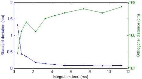
One of the important values which influence measurement accuracy of RIM camera is integration time (IT). IT defines emerging period of the signal by frequency generator unit. It should be within or above the ideal value to obtain high accuracy from the measurements. The proper value of IT varies according to the measurement surface, range and incident angle of the light (Jamtsho, 2010). The relationship between integration time and standard deviation of the distance is given on Figure 1.
Figure 1. The relationship between integration time and standard deviation of distance. The measurement has been performed on the white wall from 167cm distance with setting
30 fps and 30 MHz modulation frequency (Altuntas, 2014)
Integration time of SR4000 camera varies between 0-255 (arbitrary). These values correspond to 0.3-25.8 ms
(milliseconds) in SR4000 camera and calculated with the Equation (1) (SR4000 Manual, 2012).
(1)
SR4000 camera measurements are recorded in ASCII format and range and amplitude images are generated from these data by user codes. In each measurement file, five different values are recorded on pixel design of the camera (144x176 pixel). These are respectively Z, X, Y coordinates, amplitude and confidence map. Z coordinates are given as calibrated distances in the file. The effect of distortion in SR4000 camera coordinates were removed with factory defaults.
The differences occur between successive frames recorded from the same image area in the stable position of camera due to systematic errors. In order to minimize the effects of the errors, many frames from the same field of view are recorded and average image file is formed. The previous studies show that ten successive images are enough to precise measurement (Piatti, 2010).
Systematic errors influencing RIM camera measurements are divided into two categories dependent and independent from the environment. Systematic errors independent from the environment are radial distortion and range determination errors. Range determination errors are composed of offset, scale and time errors. The errors depend on the environment are amplitude, illumination and multipath errors varying from environment to environment (Jamtsho, 2010).
Multipath error is the case in which light turns back to camera reflecting from different surfaces. So the corresponding object point of the pixel is measured at a range further than it must be. This error is generally formed on concave surface where both surfaces intersect.
3. RESULTS
The gravel pile on civil engineering laboratory was measured by RIM camera (Figure 2). At the beginning the real volume of the gravel pile was determined with the scale cup.
Figure 2. The volume measurement of the gravel pile by SR4000 camera
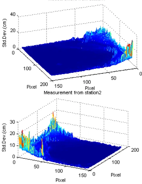
The gravel pile which has complex shape was measured from two stations by RIM camera. The 30 images were recorded in each station with integration time 3.3.ms. The mean distances between the camera and the pile are 1.17 and 1.14 meters for two stations respectively. The average image file of the recorded 30 images in each station was computed by developed Matlab in-house code. Then the standard deviation of each pixel (point) were calculated with Equation (2) (Piatti, 2010).
(2)
(3)
Here, n is the number of the measurement (frame), xi is the ith frame and σ is the experimental standard deviation of any measurement. The standard deviations of the average measurements are shown on the Figure 3.
Figure 3. Standard deviations of the average measurements from two station
This two point clouds were combined in the coordinate system of the first. For this, the second point cloud was registered into the first. The registration was made by iterative closest point (ICP) method using PolyWorks software (InnovMetric, 2007). The standard deviation of the registration is 3.21mm. In order to increase accuracy of the volume computation, on the edges, about 10 percent of the frames was ignored. Actually on the far away edge of the frame the standard deviation is high than the others (Figure 3). The triangulated surface was created and topological errors has been eliminated. The reference plane have to be defined to compute of the volume. Through the pile is on the smooth ground, reference plane was created by three
points selected on the ground (Figure 4). Then the volume between the reference plane and the triangulated surface was computed (Table 2).
Figure 4. The triangulated and mesh models of the gravel pile. The reference plane was created by three points selected from
the ground interactively
Table 2. The computed volume
The accuracy of the SR4000 camera is 1cm at 5 meter distance. In this study the measurement range is about 1m. So the errors of the distances are about 1 cm or small. On the other hand since the object sampling step (pixel size on the pile) is about 4.2mm, the pile can be measured with a large number of points. Because accuracy of the range cameras change according to reflectivity of the measured surface and other effects, the accuracy is not same level on all the pixels. Especially, accuracy of the distance is decrease when the incidence angle and the measured distance are increased. Thus the thin strip on the edges or especially the image part that have the large standard deviations have to be eliminated. If the pile is measured from more stations, the registration can be executed by ICP with high accuracy.
The pile volume was measured as different 8.13% from its real volume. The difference could be resulted from the measurement accuracy of SR4000 and pile shape.
5. CONCLUSION
In this study pile volume was measured by SR4000 camera. Considering max measurement range (5m) and pixel size on the object RIM can be used in pile volume measurement at indoor environment. Measurements can be made in high accuracy with proper camera parameters. RIM camera is fast and low-cost measurement in comparison traditional and laser scanning techniques. Further study will focused to investigate relationship between volume accuracy and surface area of the
Beringe, A.V., 2012. Performance evaluation of a range camera SR4000. Diplomarbeit, Ausgeführt am Institut für Photogrammetrie und Fernerkundung der Technischen Universitat Wien, 87 pages.
Besl P.J., McKay, N.D., 1992. A method for registration of 3-D shapes. IEEE Transsactions on Pattern Analysis and Machine Intelligence, 14(2), pp. 239-256.
Boehm, J., Pattinson, T., 2010. Accuracy of exterior orientation for a range camera. in Proc. ISPRS Commission V Mid-Term Sym., Newcastle upon Tyne, United Kingdom, Int. Arch. Photogramm. Remote Sens. Spatial Inf. Sci. XXXVIII-Part 5, pp. 103-108.
Centeno, J.A.S., Jutzi, B., 2010. Evaluation of a range imaging sensor concerning resolution and illumination. in Proc. ISPRS Convergence in Geomatics–Shaping Canada's Competitive Landscape, Calgary, Alberta, Canada, Int. Arch. Photogramm. Remote Sens. Spatial Inf. Sci. XXXVIII-Part 1, p. 6.
Chen, Y., Medioni, G., 1992. Object modelling by registration of multiple range images. Image and Vision Computing, 10(3), pp. 145–155.
Gokturk, S.B., Yalcin, H., Bamji, C., 2004. A time-of-flight depth sensor – system description, issues and solutions. Proceedings of the 2004 IEEE Computer Society Conference on Computer Vision and Pattern Recognition Workshops (CVPRW’04), 27-02 June, DOI: 10.1109/CVPR.2004.459, Vol. 3, page 35.
Hussmann, S., Ringbeck, T., Hagebeuker, B., 2008. A performance review of 3D ToF vision systems in comparison to stereo vision systems. Stereo Vision, Asim Bhatti (Ed.), ISBN:978-953-7619-22-0, InTech, pp. 103-120.
InnovMetric, 2007, Polyworks Software, InnovMetric, 2007, Polyworks Software, Beginner’s Guide,
http://www.innovmetric.com/polyworks/3D-scanners/home.aspx?lang=en (access: Jan 2013).
Jamtsho, S., 2010. Geometric modelling of 3D range cameras and their application for structural deformation measurement. Master Sciences Thesis, Department of Geomatics Engineering, Calgary, Alberta, December, 161 pages.
Jamtsho, S., Lichti, D.D., 2010. Modelling scattering distortion in 3D range camera. in Proc. ISPRS Commission V Mid-Term Symposium, Newcastle upon Tyne, UK, Int. Arch. Photogramm. Remote Sens. Spatial Inf. Sci., Vol. XXXVIII, Part 5, pp. 299-304.
Kahlmann, T., 2007. Range imaging metrology: investigation, calibration and development. PhD Thesis, ETH Zurich, 143 pages.
Kahlmann, T., Remondino, F., Ingensand, H., 2006. Calibration for increased accuracy of the range imaging camera SwissRangerTM. in Proc. ISPRS Commission V Symposium, Dresden, Germany, Int. Arch. Photogramm. Remote Sens. Spatial Inf. Sci. XXXVI Part 5, pp. 136-141..
Karel, W., Ghuffar, S., Pfeifer, N., 2012. Modelling and compensating internal light scattering in time of flight range cameras. The Photogrammetric Record, 27(138), pp. 155–174.
Lange, R., 2000. 3D time-of-flight distance measurement with coustom solid-state image sensors in CMOS/CCD-technology. PhD thesis, Department of Electrical Engineering and Computer Sciences at University of Siegen, 206 pages.
Oggier, T., Lehmann, M., Kaufmann, R., Schweizer, M., Richter, M., Metzler, P., Lang, G., Lustenberger, F., Blanc, N., 2004. An all-solid-state optical range camera for 3D real-time imaging with sub-centimeter depth resolution (SwissRanger). in Proc. SPIE 5249, pp. 534-545 doi:10.1117/12.513307.
Piatti, D. 2010. Time-of-flight cameras: Tests, calibration and multi frame registration for automatic 3D object reconstruction.
PhD Thesis, Politecnico di Torino Doctoral school of Environment and Territory.
Rapp, H., 2007. Experimental and theoretical investigation of correlating ToF-camera systems. Diploma Thesis in Physics, Insitut fur Wissenschaftliches Rechnen (IWR).
SR4000 Manual, 2012. SR4000 User manual, Version 2. MesaImaging.
URL-1: MesaImaging,
http://www.mesa-imaging.ch/prodview4k.php (acces: April 25, 2013).