THERMAL 3D MAPPING FOR OBJECT DETECTION IN DYNAMIC SCENES
Martin Weinmanna, Jens Leitloffa, Ludwig Hoegnerb, Boris Jutzia, Uwe Stillaband Stefan Hinza
aInstitute of Photogrammetry and Remote Sensing, Karlsruhe Institute of Technology (KIT) {martin.weinmann, jens.leitloff, boris.jutzi, stefan.hinz}@kit.edu
b
Photogrammetry and Remote Sensing, Technische Universit¨at M¨unchen (TUM) [email protected], [email protected]
Commission I, WG I/2
KEY WORDS:Multisensor, point cloud, thermal imaging, 3D mapping, dynamic, object detection
ABSTRACT:
The automatic analysis of 3D point clouds has become a crucial task in photogrammetry, remote sensing and computer vision. Whereas modern range cameras simultaneously provide both range and intensity images with high frame rates, other devices can be used to obtain further information which could be quite valuable for tasks such as object detection or scene interpretation. In particular thermal information offers many advantages, since people can easily be detected as heat sources in typical indoor or outdoor environments and, furthermore, a variety of concealed objects such as heating pipes as well as structural properties such as defects in isolation may be observed. In this paper, we focus on thermal 3D mapping which allows to observe the evolution of a dynamic 3D scene over time. We present a fully automatic methodology consisting of four successive steps: (i) a radiometric correction, (ii) a geometric calibration, (iii) a robust approach for detecting reliable feature correspondences and (iv) a co-registration of 3D point cloud data and thermal information via a RANSAC-based EPnP scheme. For an indoor scene, we demonstrate that our methodology outperforms other recent approaches in terms of both accuracy and applicability. We additionally show that efficient straightforward techniques allow a categorization according to background, people, passive scene manipulation and active scene manipulation.
1. INTRODUCTION
The automated description and analysis of static and dynamic 3D scenes represents a topic of major interest in photogrammetry, remote sensing and computer vision. Due to the recent techno-logical advancements, a variety of devices is currently available which can be used for acquiring different types of information such as color, temperature or spatial 3D geometry. Thus, the use of different devices on a common sensor platform allows to col-lect multidimensional spatial data.
In particular those devices delivering complementary types of in-formation offer a high potential for numerous applications. Mod-ern range cameras such as Microsoft Kinect, PMD[vision] Cam-Cube 2.0 or MESA Imaging SR4000 simultaneously provide ge-ometric information as well as radige-ometric information in form of range and intensity images, and they are also applicable for adequately capturing dynamic scenes. Whereas the radiometric information is typically represented as color or gray-valued im-ages, other devices such as thermal cameras offer to capture com-plementary information which can be helpful for describing and analyzing the observed scene and its evolution over time.
A fusion of intensity and thermal information for instance seems desirable, since the respective images reveal a very different be-havior:
• Standard intensity images (i.e. color or gray-valued im-ages) typically represent information of the visual domain and thus radiometric surface properties of observed objects. This information may strongly depend on the material and reflectance behavior of respective objects as well as the rel-ative geometric orientation of the surface to the camera.
• Thermal infrared images represent thermal radiation in the infrared spectrum. This radiation is emitted by objects in the
scene and not visible in the visual domain. Consequently, the thermal infrared images allow a different look on objects and the extraction of additional information like temperature and different materials of observed objects.
Accordingly, objects visible in the visual domain may be invisi-ble in the infrared domain if they have the same temperature and emissivity coefficient as the respective background. In contrast, in infrared images, even further objects below the surface of an object may be visible which certainly remain invisible in the vi-sual domain. Note that two different materials with the same tem-perature can appear with different intensity if they have a signif-icantly different emissivity coefficient. Interestingly, two objects with different temperature and emissivity coefficient can even co-incidentally appear with very similar intensity in thermal images. As a consequence, a fusion of intensity images and thermal in-frared images can reveal information which may not be present in either intensity images or thermal infrared images (Chen and Leung, 2009; Bai et al., 2011). This is for instance of special interest for enhancing contrast in environments of poor visibility or inadequate illumination (Liu and Lagani`ere, 2007), for target detection (Yao and Sekmen, 2008) or for concealed weapon de-tection (Xue et al., 2002). More importantly, however, infrared thermography allows for building diagnostics (Balaras and Ar-giriou, 2002) which, due to current attempts for saving energy, has become a research topic itself.
observation (Hoegner et al., 2007a; Iwaszczuk et al., 2011), the joint representation of building fac¸ades and thermal information allows a reconstruction of the surface temperature and thus a look into the interior behavior of a wall. Valuable insights about differ-ent materials, heating pipes and leakages can easily be obtained and added as semantic or geometric information to the respective building model.
In order to capture co-registered intensity information, thermal information and spatial 3D geometry, the combination of data captured with a terrestrial laser scanner and images acquired by a bi-camera system, i.e. a system consisting of an optical camera and a thermal camera, has recently been proposed (Alba et al., 2011). Furthermore, a robot equipped with a 3D laser scanner, a thermal camera and a digital camera has been presented which is capable to generate a precise 3D model showing the heat dis-tribution in the scene (Borrmann et al., 2012a; Borrmann et al., 2012b). The additional color information can for instance be used for identifying heat sources or for obtaining photo-realistic 3D models. Focusing on the acquisition of dynamic scenes, respec-tive systems addressing thermal 3D mapping involve range cam-eras such as RGB-D camcam-eras or Time-of-Flight (ToF) camcam-eras. For instance, the use of a low-cost RGB-D camera in combina-tion with a thermal camera has recently been proposed for acquir-ing dense 3D models of environments with both appearance and temperature information (Vidas et al., 2013). Involving a Time-of-Flight camera, an approach for gaining infrared-textured 3D models has been proposed (Weinmann et al., 2012) which addi-tionally focuses on sharpening the blurry thermal information by exploiting the high quality of intensity information acquired with the range camera.
In this paper, we focus on thermal 3D mapping which allows to observe the evolution of a dynamic 3D scene over time. The main contribution presented in our paper is a fully automatic method-ology for thermal 3D mapping which involves
• a geometric calibration of both the range camera and the thermal camera based on a common strategy,
• a robust approach for detecting 2D/2D feature correspon-dences via shape-based matching,
• a removal of unreliable 2D/2D feature correspondences by considering the reliability of the respective range informa-tion, and
• a novel approach exploiting 3D/2D feature correspondences for the co-registration of 3D point cloud data and thermal information.
After reflecting the related work in Section 2, we provide a de-tailed explanation of the different steps of our new methodology in Section 3. For an experimental setup described in Section 4, we present the derived results in Section 5 and discuss these with respect to different aspects in Section 6. Finally, Section 7 con-tains conclusions as well as ideas for future work.
2. RELATED WORK
For thermal 3D mapping involving a range camera, respective 3D coordinates are available for each pixel of the intensity image. Accordingly, feature correspondences have to be derived either between standard intensity images (i.e. color or gray-valued im-ages) and thermal infrared images (Section 2.1), or between 3D point clouds and thermal infrared images (Section 2.2). For the sake of completeness, we also briefly reflect approaches generat-ing 3D point clouds from thermal infrared images (Section 2.3).
2.1 Co-Registration of Intensity and Thermal IR Images
One category of approaches directly leads to basic image pro-cessing in terms of image registration (Zitov´a and Flusser, 2003). Once the respective transformation model has been estimated, the thermal infrared image can be warped onto the intensity image of the range camera, and thus also be projected to 3D space by for-ward projection according to the respective 3D information.
Among the approaches for image registration, the feature-based approaches are most widely spread. In general, we may consider any feature present in an image as visual feature. More specifi-cally, according to a recent survey on visual features (Weinmann, 2013), different types of visual features can be categorized, where texture, shape and local features are the most prominent types due to their applicability for numerous applications such as im-age registration, data retrieval, scene analysis and the autonomous navigation of aerial and ground vehicles. Typically, approaches for feature extraction and matching are tailored for images ac-quired by either identical or similar sensors from various posi-tions. However, a matching between different image domains – e.g. a co-registration of satellite imagery and LiDAR intensity images (Toth et al., 2011) – can be quite challenging as the re-spective images may have very different characteristics due to which many standard approaches for deriving feature correspon-dences tend to fail.
In particular, an automatic matching between the visual domain and the thermal domain still remains challenging. Intensity im-ages in the visual domain often provide abrupt changes of proper-ties like intensity or texture at the edges of objects in the observed scene. In thermal infrared images, however, we might face chal-lenges arising from (i) the low geometric resolution compared to classical optical camera systems and (ii) the fact that features such as lines or contours do not show strong edges, but rather appear blurred. As a consequence, even powerful standard meth-ods for deriving feature correspondences, e.g. the Scale Invariant Feature Transform (SIFT) (Lowe, 1999; Lowe, 2004), are not ap-plicable for automatically detecting feature correspondences be-tween the visual domain and the thermal domain.
For registration of image data representing information in these different spectral bands, different approaches have been proposed such as a segment-based approach (Coiras et al., 2000) or an approach involving normalized mutual information (Park et al., 2008). Furthermore, approaches for generating textured 3D point clouds often rely on a matching between images followed by for-ward projection to 3D space. For flat building fac¸ades and al-most planar scenes, the transformation model of a homography (Hartley and Zisserman, 2008) can be applied. Such a transfor-mation may for instance be exploited for mapping thermal IR in-formation on existing building models (Hoegner et al., 2007b) or thermal 3D mapping involving a range camera (Weinmann et al., 2012). The latter approach relies on deriving feature correspon-dences between the respective images via shape-based matching, a respective image registration and a subsequent forward projec-tion to 3D space. Considering mutual informaprojec-tion between im-ages has also been proposed for mapping multispectral texture information onto 3D models (Pelagotti et al., 2009) and for co-registration of intensity images and 3D LiDAR data (Parmehr et al., 2013).
2.2 Direct Co-Registration of Point Clouds and Thermal In-formation
relative orientation (Pulli et al., 1998). If the relative orientation is unknown, the standard approach consists of the manual selec-tion of tie points and a subsequent bundle adjustment based on the collinearity equations, which has recently been used for co-registering 3D point clouds and thermal infrared images (Hoeg-ner et al., 2014).
For automatically estimating the relative orientation between the used devices, silhouette-based approaches may be applied, which focus on minimizing the error between the contour of an object in the image and the contour of the respective projected 3D model (Lowe, 1991). In particular, linear features are often used as they typically occur in man-made environments such as urban areas. For such scenes, lines can be extracted at edges in 2D imagery, and clusters of vertical and horizontal lines can be detected in the respective 3D point cloud. This allows a registration based on the matching of corresponding 2D and 3D linear features (Liu and Stamos, 2005; Liu and Stamos, 2012).
As interesting alternative, which could potentially be applicable also for co-registering thermal information and 3D point cloud data, a recent approach focused on the mapping of iPhone im-ages onto LiDAR point clouds (Sirmacek et al., 2013). In this work, the extraction of shape features from iPhone images is based on conducting mean shift segmentation, nonlinear smooth-ing and applysmooth-ing steerable filters in different orientations. Further exploiting the metafile, the GPS position and the looking angle of the iPhone camera are available. These are used for defining the orientation of a virtual plane. The extraction of shape features from point cloud data is based on the perpendicular projection of LiDAR points onto the derived virtual plane, which yields a rep-resentation for those fac¸ade and roof points of a building which are the closest to the virtual plane. Extracting the alpha shape around the points, sharp corners of the alpha shape may be used as discriminative features. Finally, a co-registration of image and point cloud data is conducted by estimating an affine transforma-tion based on the extracted features.
2.3 Direct Generation of Point Clouds from Thermal IR Im-ages
In contrast to approaches involving range cameras, the direct gen-eration of 3D models from thermal images via Structure-from-Motion (SfM) techniques has been proposed (Markov and Birk, 2007). Such image-based techniques may be applied for simulta-neously recovering both 3D structure of the scene and the respec-tive pose (i.e. position and orientation) of the camera (Szeliski, 2010). Furthermore, a thermal stereo system for recovering a 3D surface temperature map of the scene has been presented (Prakash et al., 2006) which is even able to estimate object depth within a dark environment. This system is based on exploiting isotherms (i.e. lines connecting points of equal temperature) and epipolar geometry (Hartley and Zisserman, 2008), whereby the epipolar constraints reduce the correspondence search space to the inter-secting points between epipolar lines and isotherms.
3. METHODOLOGY
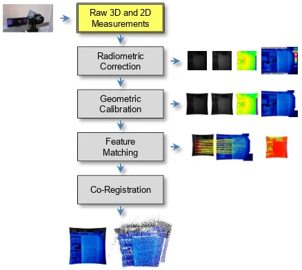
For thermal 3D mapping, we propose a methodology which auto-matically recovers the relative orientation between a range cam-era and a thermal camcam-era (Figure 1). After conducting a radio-metric correction (Section 3.1), a georadio-metric calibration (Section 3.2) is applied in order to obtain undistorted 2D imagery. Subse-quently, a shape-based technique for detecting feature correspon-dences between intensity images and thermal infrared images is
exploited (Section 3.3) and, due to the acquired range informa-tion, each 2D/2D correspondence can directly be assigned a re-spective 3D point which yields 3D/2D correspondences. Those correspondences containing unreliable range information are dis-carded via an image-based rejection strategy. The remaining cor-respondences can efficiently be used for co-registering 3D point cloud data and thermal information (Section 3.4), i.e. mapping the thermal information onto the 3D point cloud.
Raw 3D and 2D Measurements
Radiometric Correction
Geometric Calibration
Feature Matching
Co-Registration
Figure 1: The components of our methodology.
3.1 Radiometric Correction
For range cameras, the captured intensity information corresponds to the energy of the laser light reaching the device. Due to internal processes such as conversion to a digital signal and signal ampli-fication (which are not identical for different range cameras), this intensity information has to be adapted for applying standard im-age processing techniques. This is done by applying a histogram normalization of the form
In=
I−Imin Imax−Imin
·255 (1)
which adapts the intensity informationIof each pixel to the in-terval[0,255]and thus yields gray-valued images. Here, the min-imal and maxmin-imal intensity within all intensity measurements on the regular 2D grid are denoted asIminandImax, respectively. The histogram normalization can be conducted for both active and passive intensity images. For the example of an indoor scene, the recorded information is visualized in Figure 2.
For thermal cameras, there is no need to apply a histogram nor-malization as the captured thermal information of each pixel is already assigned a color value according to a certain colorbar. A respective visualization of thermal information for the provided example is depicted in Figure 3.
3.2 Geometric Calibration
For calibration, we follow a recent strategy focusing on the gener-ation of infrared-textured 3D models (Weinmann and Jutzi, 2012). This strategy involves a geometric calibration for both range cam-era and thermal camcam-era.
Figure 2: Visualization of the data captured with a PMD[vision] CamCube 2.0: Normalized active intensity image, normalized passive intensity image and range image (from left to right). The range is encoded in terms of a color scale reaching from red (near) via yellow, green, cyan and blue to violet (far).
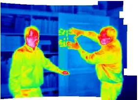
Figure 3: Visualization of thermal information captured with an InfraTec VarioCAM hr.
devices. For this purpose, we assume that the geometric mapping of a scene onto the image plane can be described with a stan-dard camera model representing the intrinsic behavior of a digital camera. This standard model considers both radial and tangential distortion (Brown, 1971; Heikkil¨a and Silv´en, 1997). Accord-ingly, the geometric mapping can be parameterized with the fo-cal lengths inx- andy-direction, the image coordinates(x0, y0) of the principal point, a skew coefficients, and the image distor-tion coefficients describing radial and tangential distordistor-tion. The well-known standard methodology then consists of using a rect-angular checkerboard pattern with known size, capturing respec-tive intensity images with the device, extracting the grid corners of the checkerboard pattern in the intensity images, and finally applying the calibration procedure (Bouguet, 2010). For the ex-ample depicted in Figure 2, the derived undistorted images are provided in Figure 4. Subsequently, the respective 3D informa-tion in the local coordinate frame can be derived (Weinmann and Jutzi, 2012).
Figure 4: Visualization of the undistorted images for normalized active intensity, normalized passive intensity and range informa-tion (from left to right).
Since the checkerboard pattern is not visible in the thermal in-frared domain, the calibration of thermal cameras is based on a planar testfield with lamps (Luhmann et al., 2010; Lag¨uela et al., 2011a; Borrmann et al., 2012b; Hoegner et al., 2014). The lamps are clearly visible in the thermal infrared images (Figure 5) and can thus easily be detected. Using a regular grid of lamps also al-lows for using the aforementioned standard calibration procedure for digital cameras (Figure 6).
Figure 5: Captured thermal information for the planar testfield with lamps. The distortion of the thermal infrared image is clearly visible.
Figure 6: Visualization of the undistorted thermal infrared image.
3.3 Detection of 2D/2D and 3D/2D Correspondences
For deriving feature correspondences between the image repre-sentations of intensity and thermal infrared information, we use local features in terms of keypoints with characteristic descrip-tors. Due to the different characteristics of the compared im-ages, commonly used keypoint descriptors obtained from algo-rithms such as SIFT (Lowe, 1999; Lowe, 2004) or SURF (Bay et al., 2011) fail in the automatic detection of point correspon-dences. Hence, we apply the shape-based matching algorithm proposed in (Steger, 2001) and (Ulrich, 2003) which matches image patches of a user-defined size by exploiting wavelength independent properties in terms of shape information. Thereby, the surrounding of a keypoint is described by a generated model. Thus, the algorithm is able to derive feature correspondences of which a certain percentage provides a high reliability.
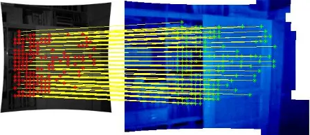
space is extended to a predefined range of rotations and scales. If the derived similarity measure is above a certain threshold, a point correspondence is detected (Figure 8). For each correspon-dence, the coordinates of the center, the rotation angle and the similarity measure itself are assigned. We use the HALCON 11 implementation (MVTec Software) of the shape-based matching algorithm for our experiments.
Figure 7: Principle of shape-based matching (Ulrich, 2003): model image (left), model edges (center) and search image (right).
Figure 8: Automatically detected feature correspondences be-tween an intensity image and a thermal infrared image for a static scene.
Since the range camera also provides range information in terms of a range image, we can easily assign each of the derived 2D/2D correspondences a respective 3D scene point whose coordinates are known in the local coordinate frame of the range camera. For estimating the relative orientation between the two utilized de-vices, we do not want to make strong assumptions on the scene structure, but rather exploit a general solution which relies on 3D/2D correspondences, where the 3D information is derived via the range camera and the 2D information is derived via the thermal camera. Depending on the surface properties of the re-spective objects, i.e. shape and reflectivity, the range camera provides more or less noisy range information. Note that many points which arise from objects in the scene will probably provide a smooth surface. However, range information of points along edges of the respective objects might be very noisy. In order to detect such noisy measurements, the standard deviationσof all range values within a3×3neighborhood is calculated for each point on the regular 2D grid and used as a measure describing the reliability of the respective range information (Weinmann and Jutzi, 2011). Combining these constraints for all points on the 2D grid yields a 2D confidence map which is illustrated in Figure 9 for two exemplary scenes.
In order to remove unreliable feature correspondences, a simple thresholding is conducted. If the parameterσof the respective range values is larger than a predefined thresholdtσ, the range information of the center pixel is assumed to be unreliable, oth-erwise the range information of the center pixel is assumed to be reliable. Following (Weinmann and Jutzi, 2012), we select this threshold totσ = 0.05m.
Figure 9: Confidence maps indicating the reliability of the re-spective range information. The reliability is encoded in terms of a color scale reaching from red (reliable) via yellow, green, cyan and blue to violet (unreliable).
3.4 Co-Registration of 3D and 2D Information
Once 3D/2D correspondences have been detected, the task of co-registering 3D and 2D information may be related to the well-known Perspective-n-Point (PnP) problem where the aim is to estimate the exterior orientation or pose of a camera from a set ofncorrespondences between 3D pointsXiof a scene and their 2D projections xi onto the image plane, wherei = 1, . . . , n. In recent years, the Efficient Perspective-n-Point (EPnP) algo-rithm (Moreno-Noguer et al., 2007) has been proposed as a non-iterative method which provides an accurate solution to the PnP problem with only linear complexity. Compared to other ap-proaches for solving the PnP problem, this algorithm is not only fast and accurate, but also designed to work with a large number of correspondences and it does not require an initial estimate.
The EPnP algorithm is based on the idea of expressing then known 3D scene pointsXias a weighted sum of four virtual and non-coplanar control pointsCjfor general configurations. De-noting the weights asαijand introducing a superscriptcwhich indicates coordinates in the camera coordinate frame, each 3D/2D correspondence provides a relation of the form
wi
xi
1
=K Xci =K 4 X
j=1
αijCcj (2)
whereKdescribes the calibration matrix. Considering the re-spective three equations, the scalar projective parameterswican be determined according to the third equation and substituted into the other two equations. Concatenating the two modified equa-tions fori= 1, . . . , nyields a linear equation systemM x=0, wherexcontains the 3D coordinates of the four control points Cj. For more details on the efficient solution of this equation system, we refer to the respective paper (Moreno-Noguer et al., 2007). Once both world coordinates and camera coordinates of the 3D points are known, the transformation parameters aligning both coordinate systems can be retrieved via standard methods involving a closed-form solution in the least-squares sense (Horn et al., 1988; Arun et al., 1987; Umeyama, 1991).
samples. In comparison to minimal subsets, this further reduces the sensitivity to noise. In order to avoid testing all possible sub-sets, which would be very time-consuming, we exploit an effi-cient variant, where the number of iterations – which equals the number of randomly chosen subsets – is selected high enough, so that a subset including only inlier correspondences is selected with a certain probabilityp(Hartley and Zisserman, 2008).
In our case, we may assume that the local coordinate frame of the range camera represents the reference coordinate frame. Conse-quently, the derived 3D coordinates are known with respect to the reference frame. Together with the respective observed 2D image locations in the thermal infrared image, they form the required 3D/2D correspondences. Note that, for this reason, the matrixK in Equation (2) refers to the thermal camera.
4. EXPERIMENTAL SETUP
For thermal 3D mapping, we use a sensor platform equipped with a range camera and a thermal camera (Figure 10), where a fixed relative orientation between the two devices is preserved.
Figure 10: Sensor platform equipped with a range camera (left) and a thermal camera (right).
4.1 Range Camera: PMD[vision] CamCube 2.0
Modern range cameras capture geometric information as well as radiometric information and thus complementary types of data in form of images, where the information is acquired simultane-ously for all pixels on the regular 2D grid. Due to the high frame rates of more than25releases per second, range cameras also al-low to capture dynamic scenes. For our experiments, the choice of the utilized device is motivated by a possible use in outdoor en-vironments, where range cameras based on the use of structured light are not applicable. We hence use a Time-of-Flight camera of type PMD[vision] CamCube 2.0, which measures three fea-tures for each pixel: range, active intensity and passive intensity. Note that the active intensity depends on the illumination emitted by the sensor, whereas the passive intensity depends on the back-ground illumination arising from the sun or other external light sources. The resulting images have a size of204×204pixels which corresponds to a field-of-view of40◦×40◦. This in turn
represents an angular resolution of approximately0.2◦.
Due to the measurement principle of such Time-of-Flight cam-eras, the non-ambiguous range depends on the modulation fre-quency. A modulation frequency of20MHz for instance corre-sponds to a non-ambiguous range of7.5m. In order to overcome this range measurement restriction, image- or hardware-based un-wrapping procedures have recently been introduced (Jutzi, 2009; Jutzi, 2012).
4.2 Thermal Camera: InfraTec VarioCAM hr
As thermal camera, we use a bolometer-based InfraTec Vario-CAM hr which records in the wavelength interval from7.5-14µm
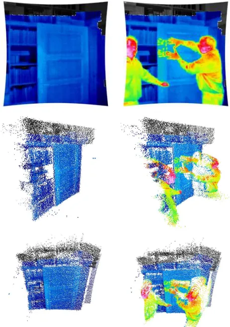
Figure 11: Visualization of thermal information mapped onto the respective 3D point cloud for two different scenes: 2D image pro-jections (top) and colored 3D point clouds (center and bottom).
with a radiometric resolution of0.05K. The captured thermal in-formation is represented as images with a size of384×288 pix-els. The angular resolution is approximately0.16◦, and thus a
captured thermal infrared image corresponds to a field-of-view of61◦×46◦. As the frame rate is25fps, this device can also be
applied for observing dynamic scenes.
5. EXPERIMENTAL RESULTS
For testing the proposed methodology, we only have to estimate the relative orientation between the utilized devices once, which is done for the example of a static scene (Figure 1). Afterwards, co-registered data can be recorded continuously when using a (hardware or software) trigger for synchronization, since the rel-ative orientation between the utilized devices is known.
6. DISCUSSION
The derived results (Figure 11) clearly reveal that the presented methodology is well-suited for thermal 3D mapping. In particu-lar, the quality is rather high due to a robust mapping between im-age data with different characteristics, where standard approaches typically tend to fail in finding reliable feature correspondences. Only a few pixels at the edges between the right person and the background are observable as being erroneous.
Without making strong assumptions on the 3D scene structure and without human interaction for selecting corresponding fea-tures, our proposed methodology is capable to fully automatically perform thermal 3D mapping in dynamic scenes. Thus, the pro-posed methodology outperforms other recent approaches which, in turn, reveal limitations as they partially rely on human interac-tion (Hoegner et al., 2014) or as they are only tailored for planar scene structures (Weinmann et al., 2012). Note that – without loss of generality – the methodology could also be applied for co-registering 3D point cloud data and color information, where the latter is acquired with a digital camera. This may even be significantly easier since the contours in both intensity images of the range camera and color images of the digital camera are not as blurry as in thermal infrared images.
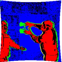
For the sake of clarity, we also want to demonstrate that the pro-posed methodology for thermal 3D mapping for instance allows to observe the evolution of a 3D scene over time. Considering the two scenes depicted in Figure 11 (center and bottom), the respective projections onto the image plane of the range camera (Figure 11, top) and further involving the undistorted intensity and range images acquired with the range camera (e.g. Figure 4) allows a categorization of (i) background where no significant changes with respect to intensity, range or thermal information are observed, (ii) people in the scene which can be observed from a change in intensity, range and thermal information, (iii) passive scene manipulation which is indicated only by a change of in-tensity information, and (iv) active scene manipulation caused by interactions between people and scene objects which is indicated only by a change of thermal information. Note that already the exploitation of thresholded difference images and a connection of logical operations allows a respective statement on change de-tection (Figure 12). From the respective rule-based classification results according to the four considered classes of changes (Fig-ure 13), a small error in the co-registration becomes visible which can also be observed in Figure 11. Accordingly, a respective seg-mentation of people in the 3D point cloud becomes trivial.
Figure 12: Thresholded difference images for intensity, range and thermal information (from left to right). Changes are indicated in white. Note the noisy behavior of range measurements.
7. CONCLUSIONS
In this paper, we focused on thermal 3D mapping as an impor-tant prerequisite for object detection in dynamic scenes. For this purpose, we presented a fully automatic methodology which in-volves (i) a radiometric correction, (ii) a common geometric cali-bration procedure for both range camera and thermal camera, (iii)
Figure 13: Results of rule-based classification based on logical operators: a clear distinction between background (blue), people (red), passive scene manipulation (yellow) and active scene ma-nipulation (green) is possible. Note that passive and active scene manipulation are also detected at edges which indicates a small error in the co-registration.
a robust approach for detecting reliable feature correspondences between different image domains by exploiting wavelength inde-pendent properties as well as an image-based rejection strategy, and (iv) a co-registration of 3D point cloud data and thermal in-formation based on an efficient and robust technique designed to work with a large number of 3D/2D correspondences. We have demonstrated that our methodology outperforms other re-cent approaches in terms of both applicability and accuracy, due to avoiding both human interaction and strong assumptions on the 3D scene structure. We have also provided an example for a possible use in order to observe the evolution of a 3D scene over time which can easily be conducted by involving straightforward techniques in terms of thresholding followed by rule-based clas-sification.
For future research, it would be desirable to not only observe a static or dynamic scene with devices mounted on a static sensor platform, but also move the sensor platform in order to capture 3D environments of larger scale and extract complete 3D models. This could for instance be valuable for building diagnostics in both indoor and outdoor environments.
REFERENCES
Alba, M. I., Barazzetti, L., Scaioni, M., Rosina, E. and Previtali, M., 2011. Mapping infrared data on terrestrial laser scanning 3D models of buildings.Remote Sensing3(9), pp. 1847–1870.
Arun, K. S., Huang, T. S. and Blostein, S. D., 1987. Least-squares fit-ting of two 3-D point sets. IEEE Transactions on Pattern Analysis and Machine Intelligence9(5), pp. 698–700.
Bai, X., Zhou, F. and Xue, B., 2011. Fusion of infrared and visual images through region extraction by using multi scale center-surround top-hat transform.Optics Express19(9), pp. 8444–8457.
Balaras, C. A. and Argiriou, A. A., 2002. Infrared thermography for building diagnostics.Energy and Buildings34(2), pp. 171–183. Bay, H., Tuytelaars, T. and Van Gool, L., 2011. SURF: speeded up ro-bust features. In: Leonardis, A., Bischof, H. and Pinz, A. (Eds.),ECCV 2006, Part I. Lecture Notes in Computer Science, Vol. 3951, Springer, Heidelberg, Germany, pp. 404–417.
Borrmann, D., Afzal, H., Elseberg, J. and N¨uchter, A., 2012a. Mutual cal-ibration for 3D thermal mapping. Proceedings of the 10th International IFAC Symposium on Robot Control.
Borrmann, D., Elseberg, J. and N¨uchter, A., 2012b. Thermal 3D mapping of building fac¸ades.Proceedings of the 12th International Conference on Intelligent Autonomous Systems, pp. 173–182.
Brown, D. C., 1971. Close-range camera calibration. Photogrammetric Engineering37(8), pp. 855–866.
Chen, S. and Leung, H., 2009. An EM-CI based approach to fusion of IR and visual images. Proceedings of the 12th International Conference on Information Fusion, pp. 1325–1330.
Coiras, E., Santamar´ıa, J. and Miravet, C., 2000. A segment-based regis-tration technique for visual-IR images.Optical Engineering39, pp. 282– 289.
Fischler, M. A. and Bolles, R. C., 1981. Random sample consensus: a paradigm for model fitting with applications to image analysis and auto-mated cartography.Communications of the ACM24(6), pp. 381–395.
Hartley, R. I. and Zisserman, A., 2008. Multiple view geometry in com-puter vision. University Press, Cambridge, UK.
Heikkil¨a, J. and Silv´en, O., 1997. A four-step camera calibration pro-cedure with implicit image correction. Proceedings of the IEEE Com-puter Society Conference on ComCom-puter Vision and Pattern Recognition, pp. 1106–1112.
Hoegner, L., Kumke, H., Meng, L. and Stilla, U., 2007a. Automatic extraction of textures from infrared image sequences and database inte-gration for 3D building models.PFG Photogrammetrie, Fernerkundung, Geoinformation6 / 2007, pp. 459–468.
Hoegner, L., Kumke, H., Schwarz, A., Meng, L. and Stilla, U., 2007b. Strategies for texturing building models with low resolution infrared im-age sequences. The International Archives of the Photogrammetry, Re-mote Sensing and Spatial Information Sciences, Vol. XXXVI-5/C55.
Hoegner, L., Roth, L., Weinmann, M., Jutzi, B., Hinz, S. and Stilla, U., 2014. Fusion von Time-of-Flight-Entfernungsdaten und thermalen IR-Bildern.AVN - Allgemeine Vermessungs-Nachrichten5 / 2014, pp. 192– 197.
Horn, B. K. P., Hilden, H. M. and Negahdaripour, S., 1988. Closed-form solution of absolute orientation using orthonormal matrices. Journal of the Optical Society of America A5(7), pp. 1127–1135.
Iwaszczuk, D., Hoegner, L. and Stilla, U., 2011. Detection of windows in IR building textures using masked correlation. In: Stilla, U., Rotten-steiner, F., Mayer, H., Jutzi, B. and Butenuth, M. (Eds.),Photogrammetric Image Analysis, ISPRS Conference - Proceedings. Lecture Notes in Com-puter Science, Vol. 6952, Springer, Heidelberg, Germany, pp. 133–146.
Jutzi, B., 2009. Investigations on ambiguity unwrapping of range images.
The International Archives of the Photogrammetry, Remote Sensing and Spatial Information Sciences, Vol. XXXVIII-3/W8, pp. 265–270.
Jutzi, B., 2012. Extending the range measurement capabilities of modu-lated range imaging devices by time-frequency multiplexing. AVN - All-gemeine Vermessungs-Nachrichten2 / 2012, pp. 54–62.
Lag¨uela, S., Gonz´alez-Jorge, H., Armesto, J. and Arias, P., 2011a. Cal-ibration and verification of thermographic cameras for geometric mea-surements.Infrared Physics & Technology54, pp. 92–99.
Lag¨uela, S., Mart´ınez, J., Armesto, J. and Arias, P., 2011b. Energy ef-ficiency studies through 3D laser scanning and thermographic technolo-gies.Energy and Buildings43, pp. 1216–1221.
Liu, L. and Stamos, I., 2005. Automatic 3D to 2D registration for the photorealistic rendering of urban scenes.Proceedings of the IEEE Com-puter Society Conference on ComCom-puter Vision and Pattern Recognition, Vol. 2, pp. 137–143.
Liu, L. and Stamos, I., 2012. A systematic approach for 2D-image to 3D-range registration in urban environments. Computer Vision and Image Understanding116(1), pp. 25–37.
Liu, Z. and Lagani`ere, R., 2007. Context enhancement through infrared vision: a modified fusion scheme. Signal, Image and Video Processing
1(4), pp. 293–301.
Lowe, D. G., 1991. Fitting parameterized three-dimensional models to images.IEEE Transactions on Pattern Analysis and Machine Intelligence
13(5), pp. 441–450.
Lowe, D. G., 1999. Object recognition from local scale-invariant fea-tures. Proceedings of the International Conference on Computer Vision, pp. 1150–1157.
Lowe, D. G., 2004. Distinctive image features from scale-invariant key-points.International Journal of Computer Vision60(2), pp. 91–110.
Luhmann, T., Ohm, J., Piechel, J. and Roelfs, T., 2010. Geometric cal-ibration of thermographic cameras. The International Archives of the Photogrammetry, Remote Sensing and Spatial Information Sciences, Vol. XXXVIII-5, pp. 411–416.
Markov, S. and Birk, A., 2007. Detecting humans in 2D thermal images by generating 3D models. In: Hertzberg, J., Beetz, M. and Englert, R. (Eds.),KI 2007: Advances in Artificial Intelligence. Lecture Notes in Ar-tificial Intelligence, Vol. 4667, Springer, Heidelberg, Germany, pp. 293– 307.
Moreno-Noguer, F., Lepetit, V. and Fua, P., 2007. Accurate non-iterative O(n) solution to the PnP problem.Proceedings of the International Con-ference on Computer Vision, pp. 1–8.
Park, C., Bae, K.-H., Choi, S. and Jung, J.-H., 2008. Image fusion in infrared image and visual image using normalized mutual information.
Proceedings of SPIE, Vol. 6968, pp. 69681Q–1–9.
Parmehr, E. G., Fraser, C. S., Zhang, C. and Leach, J., 2013. Automatic registration of optical imagery with 3D lidar data using local combined mutual information.ISPRS Annals of the Photogrammetry, Remote Sens-ing and Spatial Information Sciences, Vol. II-5/W2, pp. 229–234.
Pelagotti, A., Mastio, A. D., Uccheddu, F. and Remondino, F., 2009. Au-tomated multispectral texture mapping of 3D models.Proceedings of the 17th European Signal Processing Conference, pp. 1215–1219. Prakash, S., Pei, Y. L. and Caelli, T., 2006. 3D mapping of surface tem-perature using thermal stereo.Proceedings of the 9th International Con-ference on Control, Automation, Robotics and Vision, pp. 1–4.
Pulli, K., Abi-Rached, H., Duchamp, T., Shapiro, L. G. and Stuetzle, W., 1998. Acquisition and visualization of colored 3D objects. Proceedings of the 14th International Conference on Pattern Recognition, pp. 11–15.
Sirmacek, B., Lindenbergh, R. C. and Menenti, M., 2013. Automatic reg-istration of iPhone images to laser point clouds of urban structures using shape features. ISPRS Annals of the Photogrammetry, Remote Sensing and Spatial Information Sciences, Vol. II-5/W2, pp. 265–270.
Steger, C., 2001. Similarity measures for occlusion, clutter, and illumi-nation invariant object recognition. In: Radig, B. and Florczyk, S. (Eds.),
Pattern Recognition, DAGM 2001. Lecture Notes in Computer Science, Vol. 2191, Springer, Heidelberg, Germany, pp. 148–154.
Szeliski, R., 2010. Computer vision: algorithms and applications. Springer, New York, USA.
Toth, C., Ju, H. and Grejner-Brzezinska, D., 2011. Matching between dif-ferent image domains. In: Stilla, U., Rottensteiner, F., Mayer, H., Jutzi, B. and Butenuth, M. (Eds.),Photogrammetric Image Analysis, ISPRS Con-ference - Proceedings. Lecture Notes in Computer Science, Vol. 6952, Springer, Heidelberg, Germany, pp. 37–47.
Ulrich, M., 2003. Hierarchical real-time recognition of compound objects in images. Dissertation, German Geodetic Commission (DGK), Vol. C.
Umeyama, S., 1991. Least-squares estimation of transformation parame-ters between two point patterns. IEEE Transactions on Pattern Analysis and Machine Intelligence13(4), pp. 376–380.
Vidas, S., Moghadam, P. and Bosse, M., 2013. 3D thermal mapping of building interiors using an RGB-D and thermal camera. Proceed-ings of the IEEE International Conference on Robotics and Automation, pp. 2311–2318.
Weinmann, M., 2013. Visual features – From early concepts to modern computer vision. In: Farinella, G. M., Battiato, S. and Cipolla, R. (Eds.),
Advanced Topics in Computer Vision. Advances in Computer Vision and Pattern Recognition, Springer, London, UK, pp. 1–34.
Weinmann, M. and Jutzi, B., 2011. Fully automatic image-based reg-istration of unorganized TLS data. The International Archives of the Photogrammetry, Remote Sensing and Spatial Information Sciences, Vol. XXXVIII-5/W12, pp. 55–60.
Weinmann, M. and Jutzi, B., 2012. A step towards dynamic scene analysis with active multi-view range imaging systems.The International Archives of the Photogrammetry, Remote Sensing and Spatial Information Sciences, Vol. XXXIX-B3, pp. 433–438.
Weinmann, M., Hoegner, L., Leitloff, J., Stilla, U., Hinz, S. and Jutzi, B., 2012. Fusing passive and active sensed images to gain infrared-textured 3D models. The International Archives of the Photogrammetry, Remote Sensing and Spatial Information Sciences, Vol. XXXIX-B1, pp. 71–76.
Xue, Z., Blum, R. S. and Li, Y., 2002. Fusion of visual and IR images for concealed weapon detection. Proceedings of the International Con-ference on Image Fusion, pp. 1198–1205.
Yao, F. and Sekmen, A., 2008. Multi-source airborne IR and optical im-age fusion and its application to target detection.Proceedings of the 4th International Symposium on Advances in Visual Computing, pp. 651–660. Zitov´a, B. and Flusser, J., 2003. Image registration methods: a survey.