A UAV-BASED ROE DEER FAWN DETECTION SYSTEM
Martin Israel
Remote Sensing Technology Institute, Experimental Methods German Aerospace Center
Oberpfaffenhofen, 82234 Wessling, Germany [email protected]
http://www.dlr.de/caf
KEY WORDS:UAV, Thermal Imaging, Animal Rescue, Animal Welfare, Remote Sensing, Detection System, Agri-culture, Octocopter
ABSTRACT:
This paper presents a UAV based remote sensing system for the detection of fawns in the meadows. There is a high demand because during pasture mowing many wild animals, especially roe deer fawns are killed by mowing machines. The system was tested in several real situations especially with differing weather and iluminating conditions. Its primary sensor is a lightweight thermal infrared camera. The images are captured onboard of the flight system and also transmitted as analog video stream to the ground station, where the user can follow the camera live stream on a monitor for manual animal detection. Beside a high detection rate a fast workflow is another very important objective for this application. Therefore a waypoint planning software was developed that accelerates the workflow. At adequate illuminating and weather conditions the presented UAV-based fawn detection via thermal imaging is a comfortable, fast and reliable method.
1 INTRODUCTION
Beside economic benefits the progressive industrialization of agriculture involves also problems. Growing working width and higher velocities of the harvesters lead to an in-creasing danger for wild animals living in the farmland. Roe deer (capreolus capreolus) fawns are classic hiders (Espmark, 1969) and therefore frequent victims of agri-cultural accidents. They lie hidden in seclusion for most of the time during their first two months of life (Jarnemo, 2002). The cultivated pasture farmland is a favored bed-site for the neonate roe deer, because it screens them from the predators’ view. 96% of the fawns are born between May and June (Rieck, 1955), the time of pasture mow-ing. Because of their innate instinct to remain motion-less on the ground, they are often overlooked by farm-ers. About 25% of the newborn deers are killed during pasture mowing (Jarnemo, 2002). Beside animal welfare there is another reason for the importance to avoid these accidents. If the carcasses get undetected in the silage, bacteria produce a mortally poison (botulinum toxin) that causes health hazard in the fodder for cows, resulting in critical economic loss for the farmer. Since the beginning of the agricultural industrialization people try to prevent these accidents. Within the Game Guard project several systems are developed (Israel et al., 2010).
There are two approaches to do that: shooing the animals by scaring devices or detecting and carrying them away. The first one follows the idea, that the does will choose another area for fawn bed site, and they will remove their fawns already hiding in the field (Jarnemo, 2002). An au-thoritative study that evidences success with this method does not exist and in several tests with plastic bags as scaring device fawns lay in the same region two days after mounting the devices. In some cases fawns actually were found directly beside the scaring device. We are conviced, that this method does not work properly. The system de-scribed in this contribution follows the second approach
(to detect the animals and carry them away).
Actually it is not really easy to find a fawn in the meadow. In the visible spectrum the fawns are very good camou-flaged. They have no scent in the first days of life and they keep silent and motionless on the ground. The evo-lution has done a very good job to adapt them to the surrounding, so that for predators and people it’s hard to find them.
Figure 1: thermal image of a fawn
In the thermal infrared spectrum fawns are not adapted that perfectly. The coat of the newborn deer is barely in-sulating. Therefore it is detectable with a thermal camera if the surrounding is cold enough (figure 1). But even with a hand-held thermal camera a walking person hardly finds a fawn in the meadow. The grass of the meadow in which fawns prefer to lie is that dense that the thermal radiation does not penetrate it.
2 MATERIAL AND METHODS
2.1 Geometric considerations
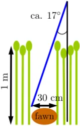
This section treats with the geometric condition that en-ables the detection of fawns with a camera. The trigono-metrical equation
tan(α) =f h =
¯ f ¯
h (1)
shows that the maximum angle deviationα between the viewing direction and the nadir is ca. 17◦in order to detect
a fawn with a sizefof 30 cm in a meadow with an average grass heighthof 1 m due to visual occlusion (figure 2). ¯fis half of the swath and ¯his the distance between the camera and the ground.
Figure 2: geometric boundary conditions
So for this application the camera works best with a 34◦
field of view angle (the double of α) for optics pointing down vertically. Then the grass can only occlude a fawn completely at the edges of the image independently from the distance of the camera to the ground. The higher the distance the larger is the covered area with one picture. But with increasing distance the ability to detect a fawn decreases due to less detailed information. Equation 1 can also be used to calculate the swath of the camera with a given field of view (FOV) angle and distance to the ground. The size of one pixel on the ground is given by
s=2 ¯f
p (2)
wherepis the cameras amount of pixels. Solving equation 2 for ¯fand substituting ¯fin equation 1 results in equation 3, which shows the correlation between the flight altitude ¯
hand the sizes that represents one pixel on the ground without regarding aberrations.
¯
h= ps
2tan(α) (3)
When the mean body temperature of the fawn holds all the neccesary information to classify the fawn in the meadow, then a pixel resolution corresponding to the size of a fawn would be sufficient. According to the Nyquist-Shannon sampling theorem (equation 4) the sampling frequency fsamphas to be more than twice of the highest information
relevant frequencyfmax to avoid information loss
(Shan-non, 1949). That means: size of a fawn is about 30 cm, therefore the pixel size on the ground has to be less than 15 cm.
fsamp>2fmax (4)
Considering all this the commercially available thermal camera core Tau640 from FLIR with 640×512 pixels and optics with 32◦
×26◦FOV was selected. Using equation 3 the camera with this specification can theoretically detect a fawn in the meadow from a maximum altitude of 166 m. Flying at a lower altitude raises the detection certainty. 2.2 System description
Figure 3: flying Game Guard in action
We mounted our thermal camera on the micro air vehicle (MAV) Falcon-8 from Ascending Technologies GmbH (fig-ure 3). A rotorcraft like this Octocopter is able to hover due to its GPS-, pressure- and magnetic field sensor. This allows capturing georeferenced high quality images of the scene. In our application we scan the whole area by fly-ing line by line capturfly-ing images in a stop-and-go mode at equidistantly spaced waypoints. The red line in figure 4 shows a schematic flight path. The gray quadrangles repre-sent the observed area on the ground. There is an overlap in both directions to guarantee full coverage. The blue circle represents the MAV. Flying at high altitude means the camera covers a wider swath. A shorter flight path is needed to cover the whole area than by flying at lower altitude. Moreover less waypoints are necessary and that saves time, because settling the waypoint, stoping for cap-turing and accelerating to reach the next waypoint takes a while. The disadvantage in flying at high altitude is the lower resolution. Identifying the fawns is therefore more difficult. Detecting hot spots at high altitude and identify them at lower altitude is a promising approach.
Figure 4: coverage of the field
is sent through a 5.8 GHz radio link to a monitor at the ground station, where the pilot can follow the view of the onboard camera. In parallel the images are captured on-board via a frame grabber by a miniature computer on module (Gumstix) with a Linux operating system. The capturing software on the Gumstix is triggered by a Uni-versal Asynchronous Receiver Transmitter (UART) pack-age sent by the Falcon-8 while it reaches the next waypoint. The UART package contains the current GPS position, flight altitude and camera inclination angle. This informa-tion and the thermal image are stored for each waypoint on a microSD card. The pattern recognition algorithm prospectively sends its results via the UART interface and the radio link down to the ground station to inform the pilot and give him a decission support.
Figure 5: system architecture diagram
At many other UAV-based pattern recognition projects the images were sent directly to the ground station, where a pattern recognition algorithm processes the images. Our system has the pattern recognition machine onboard. This prevents difficulties with interferences of the video trans-mission via radio link, but involves less cpu power for the pattern recognition due to the limited payload. Addition-ally we have mounted a visual camera on the payload. Switching between the two video sources that are displayed on the monitor can be done remotely at the ground sta-tion. The pattern recognition algorithm does not yet work on the gumstix, therefore currently the user has to detect the fawn by following the video stream on the monitor (Is-rael and Evers, 2011).
2.3 Workflow
Once the grass has grown and the weather forecast predicts sunny weather, all the farmers are mowing at the same time, because before making silage the cut grass has to dry some hours. Therefore searching fawns in the time of pasture mowing is a really time critical task. The less time it takes to detect a fawn, the more fawns can be saved. For fawn detection and rescueing with the flying Game Guard at least two persons are necessary. One person acts as pilot: He has to keep an eye on the flight system and has to bring it manually save to the ground in emergency cases. Another person (at best the tenant of the local hunt) is required to walk to the fawn and carry it away. A third person might be useful to operate the pc, communicate with the hunter and keep track of the thermal videostream on the monitor.
The workflow is shown in figure 6. It consists of the follow-ing processes: waypoint plannfollow-ing and preparation is a task that has to be done before the flight. Often the flight path can be defined at the earliest while standing at the edge of the meadow, because sometimes a good launch position can be assessed only on site. Hot spot detection and place-marking them happens while flying the search mission at a
Figure 6: Workflow of the fawn rescueing process
high altitude (30 to 50 m). Fawn identification is the next step. The pilot manually positions the copter in a lower altitude above the placemarked hot spot and tries to iden-tify it by observing the thermal and visual videostream on the monitor. The GPS position of an identified fawn is noted in a hand-held GPS device. After the flight this tool guides the hunter to the fawn’s position. If the hunter does not find the fawn with his GPS device, then an assisted recovery with the octocopter will yield the desired result: The pilot can guide the hunter by watching the scene from above. Rescueing the fawn is a process the hunter can do by himself. He picks it up with gloves or hassocks so that the fawn does not acquire the odor of the human. Then he carries the fawn away of the meadow and pens it in a cage to prevent it from refraining to the field. After mowing the field the hunter can release the fawn.
Figure 7: Screen shot of the Waypoint Editor
scan area causes an automatic adaption of the waypoints. The software shows the calculated flight path as a yellow line. Every waypoint is marked by a blue dot surrounded by the field of view on the ground which is represented by a transparent blue rectangle.
The flight altitude of the Falcon-8 is measured by a prea-sure sensor. Therefore statements on the flight altitude are referenced relatively to the starting position. Flying in a line on the same altitude above hills causes a variation of the distance to ground. In worst case this variation can lead to a gap in the image coverage. To avoid this the Way-point Editor adapts the flight altitude of each wayWay-point based on an elevation map the Google Maps Elavation API provides. The resulting waypoint list can be imported into the autopilot software.
2.4 Thermal camera
To reach a high sensitivity each pixel of the thermal de-tector (focal plane array) provides a 14-bit signal (>15000 grey levels). The human visual system can distinguish only approx. 128 levels of grey (7 bit) in an image. In addi-tion many analog and digital video interfaces require 8 bit values which effectively limits the dynamic range to 256 levels of grey (Högasten and Lindner, 2009). Hence the raw image with 14-bit has to be compressed. Most of the common thermal cameras provide an automatic gain con-trol (AGC) that calculates a high contrast for the scene. FLIR offers some parameters (Plateau Value, ITT Mean and Max Gain) to influence the results of their automatic gain control.
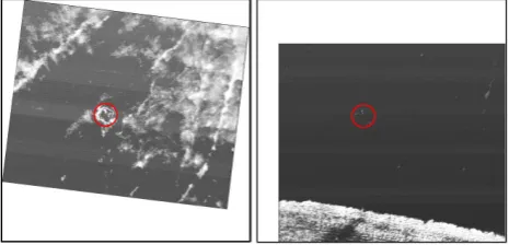
Figure 8: variation of the contrast with the Automatic Gain Control. Flight altitude: 30 m
Figure 8 demonstrates the reduction of contrast of a scene with standard AGC configuration when a warm area comes into view (right image). The red circle marks the same fawn surrounded by a fence in both pictures. It often hap-pens that there is a street at the edge of a field, which is warmer than the vegetation. Therefore we decided to change the AGC configuration and use the linear histogram equalization instead. This proved to be by far more ro-bust for these situations compared to standard plateau histogram equalization.
Some hot spot examples are shown in figure 9. These im-ages are captured during field campaigns in May 2011. The small images on the left are enhanced 64×64 pixel sized cut-outs of captured thermal images. The upper images are no fawns (a: warmed ground spot, b: anthill, c: hay bale) and the lower images are fawns (on image d are even two fawns). Image a, b, d and e are taken from an altitude of 30 m, the rest from 50 m. Image f is a cut-out of the full-sized thermal image g. At a flight altitude of 50 m a fawn is represented by just 40 of 327680 pixels.
Figure 9: thermal image cut-outs of typical hot spots at a flight altitude of 30 and 50 m
3 RESULTS AND DISCUSSION
In May and June 2011 we arranged field campaigns on 15 days. 70.77 hectare (ha) were scanned at different time of day, illuminating and weather conditions. 44.2 ha were scaned at 22 flights at a flight altitude of 50 m and 26.6 ha at 28 flights at 30 m. The average time of flight to scan one hectare at an altitude of 50 m was 3:47 minutes. At an altitude of 30 m it was 8:48 minutes. Launching and landing took about one minute.
Flying higher than 50 m sometimes led to a fawn miss even at best illuminating and weather conditions. At worse conditions flying at 30 m often could improve the fawn recognition. Flying lower than that is not practical due to the limited search performance.
At all flights the image overlap in both directions was 30 %, which led to a complete coverage of the scan area at all missions. For missions at flat areas a lower value could suffice. During the campaigns we found with this system 14 fawns, three adult deers, five rabbits, one fox and some smaller animals. Most of them were found between 2nd and 7th of June. The illuminating conditions at these days were optimal. At the field campaigns between 10th to 26th the illuminating conditions were disadvantageous. Just one fawn could be found.
This year the vegetation height was very low due to a dry and very hot period in April. Thus, many farmers mowed their meadows in May at a vegetation height of less than 40 cm. Because fawns prefer to lie in meadows with higher vegetation this year less fawns are killed during mowing.
4 CONCLUSIONS AND FUTURE WORK
ACKNOWLEDGEMENTS
The work described is part of the Game Guard Project which is funded by the Bundesministerium für Bildung und Forschung (BMBF). The author would like to thank Dr. Moser from Bad Zell in Austria for his helpful support and expertise in the field of fawn rescueing. Thanks also go to Daniel Gurdan (CEO from Ascending Technologies GmbH) for his quick support and especially for the custom adaptions of the flight system.
REFERENCES
Espmark, Y., 1969. Mother-young relations and develop-ment of behaviour in roe deer: Capreolus capreolus l. Högasten, N. and Lindner, R., 2009. Digital detail en-hancement (dde). Technical report, Flir.
Israel, M. and Evers, S., 2011. Pattern recognition for fawn detection in thermal images. In: 17. Workshop Computer-Bildanalyse in der Landwirtschaft - Computerized Image Analysis in Agriculture.
Israel, M., Schlagenhauf, G., Fackelmeier, A. and Haschberger, P., 2010. Study on wildlife detection dur-ing pasture mowdur-ing. In: 68. Internationale Tagung LAND.TECHNIK, Braunschweig.
Jarnemo, A., 2002. Roe deer capreolus capreolus fawns and mowing-mortality rates and countermeasures. Wildlife Biology 8(3), pp. 211–218.
Rieck, W., 1955. Die Setzzeit bei Reh-, Rot-und Damwild in Mitteleuropa. Zeitschrift für Jagdwissenschaft 1(2), pp. 69–75.