Simulation of IP Traceback with Efficient
Probabilistic Packet Marking Algorithm on
Distributed Denial of Service Attacks
Jana Siti N. Khasanah, Irwan Sembiring
Abstract---The attack of distributed denial of service (DDoS) is a raising issue occurring nowadays on the Internet with the concern on the denial of the legitimate services. One of the major obstacles in overcoming the attack is the fact that the attacker uses a spoofed IP, a fake address for source IP address. Probabilistic packet marking (PPM) enables victims of the attack to traceback the source of the attack when they receive a fake source IP address. The implementation of PPM requires sufficient spaces of IP header to store information of the paths that a packet passes through. Some IP packets will be marked probabilistically on the router with an IP address from the interface in which the packets are received. Each marked packet is partial information of the paths that have been passed through by the packets. Thus, all paths affected by a single attacking packet will be able to be reconstructed after information from several marked packets is gathered. Index Terms---IP Traceback, Distributed-Denial-of-Service, Probabilistic Packet Marking Algorithm, Efficient Probabiliatic Packet Marking Algorithm.
I.
Introduction
Denial of service (DoS) attack blocks an authoritative user from accessing resources of particular networks. The resources of particular networks can be in the forms of a website, a web service, or a computer system. The attack may also block the access toward information, system, application, and communication. DoS attack affects the work of a website by keep repeating the same request to its server. This attack will cause to an affected server keeps in busy of serving sent requests and eventually stops its activities because the request are overloaded [1].
Distributed Denial of Service (DDoS) attack is a well-organized attack that utilizes many computers to launch an organized DoS attack toward one or more than one targets. By using client or server technology, the
attacker can improve the effectiveness of Denial of Service significantly by manipulating sources without being noticed by other computers that take part in the attacking platform [2].
Most of the DDoS victims often find difficulties to stop the attack because the attacker uses the spoofed IP to launch it so that the source address of the attack will be difficult to be identified. The algorithm of Probabilistic Packet Marking (PPM) can help finding the source of DDoS attack that utilizes a spoofed IP as its weapon. To find out the source of DoS attack, PPM recognizes two procedures i.e. packet marking procedure and path reconstruction. The algorithm of Probabilistic packet marking (PPM) is modified into the algorithm of efficient probabilistic packet marking (EPPM) in order to improve its effectiveness.
This research utilizes a sub-technique of forensic called IP traceback. IP traceback will record and save the data traffic patterns during the DDoS attack by giving marks on some packets. The marked packets are analyzed and their paths are then reconstructed to find out the source of the attack [3].
II.
Literatur Review
To avoid the overhead of packet marking in the router, the probabilistic sample taken should be 25%. The packet-marking algorithm proposed by Savage [4], does not store a complete path of packets, rather it only records the path passed through by packets from the attacker to the victims probabilistically. The router will encode information in three fields that mark the attacking
The technique of packet marking probabilistically as it is defined in [4] is an approach to solve the problems of DoS attack. This technique utilizes a large number of packets used in the attack. If probability p marks identically on each router, the probability of packets marked with the router with the distance of d hop will be able to be seen in the equation 1 [4].
Pm(d)=p(p-1)d d≥0 (1)
Where the equation is the derivative function used to conduct the reconstruction of the victims. Pm is a marking probability number with its values ranging from 0 to 1. The values of pm on each router are not the same depending on the distance d toward the victims. The further the router is from the victims of DDoS attack, the smaller the probability happens to mark the data packet sent by the attacker.
III.
Experiment
There are two attempts of DoS attacking simulation that are attacking simulation using the real IP address and attacking simulation using the spoofed IP address. The address, utility traceroute is used to trace it back so that it will reveal the paths that the packets have passed through. The spoofed IP simulation utilizes DoS tool to send some packets to the intended victim. This way, the attacker uses the spoofed IP so that the victim will find difficulties in identifying information of the source attack because the address that the victim obtains is not the real one.
There are two simulations to find out the source of DDoS attack on the flash EPPM simulation i.e. packet marking simulation and path reconstructive simulation. The source of DDoS attack that uses the spoofed IP can be traced back by using the algorithm of Probabilistic Packet Marking (PPM). This method is preferable to be conducted as it is impossible to use traceroute as the tool
in finding out the source of the attack that collaborates IP spoofing technique.
In packet marking simulation, the attacking packets are marked by the routers of where the packets pass through. This way, the victim will be able to trace back the path by using the marking done by each router though the attacker used the spoofed IP. Each router will manually configure the marking that uses the algorithm of Probabilistic Packet Marking. In the other hand, path reconstructive simulation starts from the victim point of view toward the attacker by using the packets marked by the routers. This technique is used to find out the source of the attack by tracing back the paths passed through by the attacking packets.
IV.
Findings and Discussions
The implementation of the simulations is conducted through two ways i.e. laboratorial experiment and flash simulation. Laboratorial experiment carries out DoS attack in two categories i.e. DoS attack with the real IP address and the one with the spoofed IP address. DoS attack with the real IP address will make use of TCP and UDP protocol after identifying the source of the attack and tracing it back. The attack that uses UDP protocol is done from PC2 (192.168.2.10) by sending a large number of packets from UDP protocol directly to its server (192.168.1.10). The attack using UDP protocol can be seen in figure 1.
Fig. 1. DoS attack with UDP and its server’s responses
is closed. DoS attack with TCP and its server’s responses are shown in figure 2.
Fig. 2. DoS attack with TCP and its server’s responses
The attack without using the spoofed IP address can be detected easily because the packets can be investigated immediately using tracerouter by following the path passed through by each packet that directs to the IP address. For instance, it is detected that the IP address received by a victim is 192.168.2.10 wherein it allows to a direct tracing to the detected address and to identify the path of the data as well as the source of the attack so that the attack can be disconnected easily from the side of the attacker.
Fig. 3. tracing the source of the attack by using tracerouter
The tracing by using tracerouter as shown in figure 3 will only be effective if the attacker uses the real IP address and additionally the path does not experience congestion. The source of DoS attack using the spoofed IP is difficult to be detected because the IP address identified by each received packet varies.
The algorithm simulation of EPPM is conducted by using flash. This EPPM simulation is carried out due to the fact that the attacker uses the spoofed IP address very often as an effort to make it difficult for the victim to find out the source of DoS attack. The packets sent by using the spoofed IP address will be very difficult to be traced with the tracert so that it is preferable to use packet marking as the tool to find out the source of DoS attack. The simulation of packet marking is shown in figure 4.
Fig. 4. the simulation of packet marking
Pm is a marking probability number with its values ranging from 0 to 1, and is configured manually on each router. Meanwhile, x represents the positive numbers below 1 that are generated randomly by each router. The numbers of x can be used as a perimeter to determine whether a packet needs to be marked or not.
Marking procedure at router R
for each packet w
let x be a random number from [0..1) if x < Pm then
write R into w.start and 0 into w.distance else
if w.distance = 0 then write R into w.end increment w.distance
Fig. 5. Packet Marking Algorithm
address in the end field. In packet marking procedure, the router will be able to continually choose to start encoding on other sides randomly though the packets are already marked in one side. Thus, when a packet gets to a certain victim, the router can either encode one side of the packets or even not encoding any sides. According to the algorithm of Probabilistic Packet Marking, a packet may leave a mark on the sides or may not with the probability. For instance, if Pm(d) indicates that one certain side, in which d hop is far from the location of the victim, is marked, the marking probability will be able to be calculated with the equation 1.
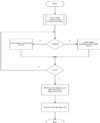
Attack Graph Construction Procedure at Victim V
let G be a tree with root being victim V ; let edges in G be tuples(start,end,distance); for (each received marked packet w) {
if(w.distance==0) then
insert edge (w.start,V,0)into G ; else
insert edge (w.start, w.end, w.distance)into G; }
remove any edge (x,y,d)with d ≠ distance from x to V in G ;
extract path (Ri…Rj)by enumerating acyclic paths in G ;
Fig. 6. rekonstruksi grafik prosedur
Fig. 7. the diagram of path reconstructive algorithm
Figure 7 illustrates the attack graph construction algorithm. G is tree-like graphic with the victims (web server) as its root. G graphic is a function of start, end, and distance. Start and end are two routers with start as the closest router from the attacker (agent 1) that possesses the distance hope from the victims, while end is the next router to the start router. Variables x, y, and d are the router’s addresses with distance d hop.Ri...Rj are R1, R2, etc. Each of variable w and n is the number that represents the number of marked packets as well as the number of repetitions.
The algorithm of EPPM utilizes additional field called as flag, which requires either 0 or 1. The initial value of flag is 0 and it will be 1 when it hits end field. The start field will be encoded if its flag is 0. When the flag is 1, it shows that the start and end field will be encoded together on the attacking graphic [2]. Efficient probabilistic packet marking algorithm shown in figure 8.
Marking Procedure at router R
For (each packet w received by the router) {
generate a random number x between [0..1]; If(x < pm and flag=0) then
/* router starts marking, flag 0 implies that the packet is not encoded previously*/
write router’s address into w.start and 0 into w.distance else
{
If (w.distance=0) then
write router address into w.end and 1 into flag }
/*flag 1implies that the packet has encoded an edge and no other successive routers should start encoding*/ If (flag = 1) then
Increment w.distance by 1
/*w.distance represents the distance of the encoded edge from the victim V*/
}
Fig. 8. Efficient Probabilistic Packet Marking Prosedure
Fig 9. network topology
Figure 10 explains the way how to divide identification field: 3 bits of offset state 8 possible kinds of fragment, other 5 bits represent ‘distance’, and the other 8 bits represent fragment’s edge. The hash as many as 32 bits are utilized in order to double the size of the router’s addresses up to 64 bits. However, it implies to the need of 8 separate fragments to represent every single edge – each fragment will be coded with unique offset numbers. The 5 bits that represent ‘distance’, in which the maximum hop for the distance is 31 hops, are sufficient because this number is over the maximum number of hop of the Internet in general.
Fig. 10. Overload IP header from Savage
The technique of EPPM is chosen in order to maximize the performance of the implementation of software. In general, adding the distance filed is the only way to modify the packet, wherein it gives direct impact to the reduction of values on time-to live (TTL) field performed by each router – by only performing the adding on the distance field, the reduction on TTL field, and the comparison to clarify whether overflow happens between the two fields or not.
To prepare for the worst, the algorithm provided should be able to read the IP identification field, to refer on an edge fragment and to XOR the fragment, and finally to perform the checksum procedure. Since the IP identification field is utilized, the problems of backward compatibility in the IP fragment’s traffic must be answered comprehensively. A perfect solution for this problem seems to be abstain for sure, that it is a necessary step to consider disadvantage compromises for the fragmented traffic. Fortunately, recent researches reveal that less than 0,25% of packets are fragmented [5]. In additional, it has been long understood that the fragmentation on network layer disturb the performance of end-to-end badly, thus, stack on the modern computer network applies an automatic MTU discovery to avoid fragmentation. Therefore, it is quite convincing that the encoding proposed will likely work appropriately with the existing protocol even though there are very small numbers of legal traffic that are fragmented.
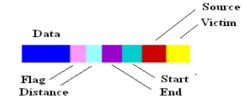
Packet marking
Fig. 11. The struktur of data packets
Figure 11 shows the structure of data packets on the simulation of DDoS attack. The data packets are then divided into several segments in order to simplify the explanation. By using the equation 1, for example, opportunity (probability) to mark each package is 25% (p=0,25) then the value of Pm for router R1 with d=3, is Pm(3)= 0,25 (1-0,25)3
In a similar way, the value of Pm for R2, R3, and R4 are as follows
- Router R2: Pm = 0.141, where d = 2 - Router R3: Pm = 0.188, where d = 1 - Router R4: Pm = 0.250, where d = 0
(lane 1) carried out attacks against the web server by sending a large number of packets pass through R1, R2, R3 and R4. The packages will be examined by every router uses an algorithm EPPM. Attacker of agent 1 (lane 1) carried out attacks against the web server by sending a large number of packets through R1, R2, R3, and R4. The packages will be examined by every router uses an algorithm EPPM. There are four possibilities to be performed by a router on every packet that passes :
- Mark the package by writing the address of the router at the start and set the distance = 0, or
- Mark the package by writing the address of the router on the end and set flag = 1, or
- Mark packages by increasing the distance value 1 point, or
- Allowing data packets passing away
If the probability p to mark the passing packets is 25% and the number of packets sent from agent 1 is 10000 packets/second, then :
- On the R1: 1050 package will be marked, 8950 package will be unmarked
- On the R2: 1410 package will be marked, 8590 package will be unmarked
- On the R3: 1880 package will be marked, 8120 package will be unmarked
- On the R4: 2500 package will be marked, 7500 package will be unmarked
The calculations of packet marking can be found as follows :
Router R1
From 10000 packets/second received by R1, there are 1050 packets that will be marked :
- 1/3 of the total packets (350 packets) are given the address of R1 on the start and the score of 0 on the distance, if x<pm and flag=0. Distance=0 means that R1 is close to the source of DDoS attack. Flag=0 means that the packets are not marked yet.
- 1/3 of the total packets (350 packets) are given the address of R1 on the end and the score of 1 on the flag, if x>pm or flag=1 and distance=0.
- The score of each packet’s distance of 1/3 of the total packets (350 packets) will be raised one digit, if flag=1 and distance>0.
Fig. 12. the structure of data packet marked by R1
Router 2
Like R1, R2 also detects 10000 packets/second, and 1410 packets will be marked :
- 1/3 of the total packets (470 packets) are given the address of R2 on the start and the score of 0 on the distance, if x<pm and flag=0. Distance=0 means that R2 is close to the source of DDoS attack. Flag=0 means that the packets are not marked by the previous router yet.
- 1/3 of the total packets (470 paket) are given the address of R2 on the end and the score of 1 on the flag, if x>pm or flag=1 and distance=0.
- The score of each packet’s distance of 1/3 of the total packets (470 packets) will be raised one digit, if flag=1 and distance>0.
Fig. 13. the structure of data packet marked by R2
Router 3
R3 detects 10000 packets/second. There are 1880 packets that will be marked :
- 1/3 dari paket tersebut (627 paket) are given the address of R3 on the start and the score of 0 on the distance, if x<pm and flag=0. Distance=0 means that R3 is close to the source of DDoS attack. Flag=0 means that the packets are not marked by the previous routers yet.
- 1/3 dari paket tersebut (627 paket) are given the address of R3 on the end and the score of 1 on the flag, if x>pm or flag=1 and distance=0.
- The score of each packet’s distance of 1/3 of the total packets (627 packets) will be raised one digit, if flag=1 and distance>0.
Fig. 14. the structure of data packet marked by R3
Router R4
R4 detects 10000 packets/second. There are 2500 packets that will be marked :
- 1/3 dari paket tersebut (833 paket) are given the address of R4 on the end and the score of 1 on the flag, if x>pm or flag=1 and distance=0.
- The score of each packet’s distance of 1/3 of the total packets (833 packets) will be raised one digit, if flag=1 and distance>0.
Fig. 15. the structure of data packet marked by R4
Path Reconstruction
Appendix 1 shows how the victim trace down the paths passed through by the packets that have been marked by the routers. Firstly, the victim will check whether the value of w.distance is 0 or not. If w.distance=0, there will be 4 possibility paths :
If w.distance=2, there will be 4 possibility paths : - Start=R1, end=R2, distance=2 (passing through R3) - Start=R1, end=R2, distance=2 (passing through R4) - Start=R1, end=R3, distance=2 (passing through R4) - Start=R2, end=R3, distance=2 (passing through R4) If w.distance=3, there will be 1 possibility path :
- Start=R1, end=R2, distance=3 (passing through R3, R4) A packet sent by an attacker is ideally marked starting from router R1 followed by R2, R3, and R4. This kind of marking will simplify the way to trace the location of the attacker. However, the probabilistic marking raises one obvious possibility where the packets are not marked orderly as it is described by appendix 1. To reconstruct the paths correctly, the victim should follow the following information :
- Start=R1, end=R2, distance=3 (passing through R3, R4) - Start=R2, end=R3, distance=2 (passing through R4) - Start=R3, end=R4, distance=1
- Start=R4, end=Victim, distance=0
V.
Conclusions
IP traceback that makes use of EPPM consists of two techniques i.e. packet marking and path reconstruction. Packet marking is implemented within the router while path reconstruction is implemented within the software application possessed by the victim. As it is mentioned earlier, the prominent advantage of utilizing EPPM is its ability to help the victim determine the source location of DDoS attack, which hides the actual IP address using IP reconstruct the paths that direct to the source of the attack.
Nevertheless, EPPM also possesses a weakness on that of the value of Pm completely depends on the distance of the victim. The path reconstruction is likely impossible to be done if the attacker set a value of flag=1 and distance > 1 in purpose. EPPM is utilized to trace back the source of the attack one by one, thus it is only effective if the attacker is just in a small number.
References
[1] Dulaney, Emmet. 2009. CompTIA security+ deluxe study guide. Indiana : Wiley Publishing, Inc. [2] Stephen Specht, Ruby Lee. 2003. Taxonomies of
Distributed Denial of Service Networks, Attacks, Tools, and Countermeasures. Department of Electrical Engineering Princeton Architecture Laboratory for Multimedia and Security. Technical Report CE-L2003-03.
[3] Savage, David Wetherall, Anna Karlin and Tom Anderson. 2000. Practical Network Support for IP Traceback. University of Washington seattle, WA, USA
[4] P.Niranjan Reddy, Y.Bhavani an efficient ip traceback through packet marking algorithm, International Journal of Network Security & Its Applications (IJNSA), Vol.2, No.3, July 2010. [5] Chao Gong, Kamil Sarac. Toward a More Practical