52 – 60 Diponegoro Rd., Salatiga, Indonesia 50711 2
Department of Biomedical Engineering, Chung Yuan Christian University 200 Chung Pei Rd., Chung-Li, Taiwan R.O.C. 32023
email : [email protected], [email protected]
ABSTRACT
The paper introduces a tetra-polar bioelectrical impedance analyzer design using microcontroller which can provide information regarding body composition based on bioelectrical impedance analysis (BIA). The primary objective of this development is to provide a non-invasive, valid, and reliable technique of estimating human body composition. In this research, body composition is divided into body fat (BF), body water (TBW), and body muscle (BM) which is displayed in percentage using character liquid crystal display (LCD). The
analyzer uses Fricke’s electrical circuit to model the behavior of biological tissues in vivo. From current stimulus perspective, the analyzer is categorized multi-frequency BIA means the circuit uses different frequencies to evaluate body composition. The method of injecting current to body and measure the voltage drop is tetra-polar method. A prototype has been developed and the performance has been evaluated. The system was tested on the human body repeatedly over certain period and the gathered data set is analyzed. The data analysis indicates that BF, TBW, and BM estimation has maximum error 2.82%, 0.65%, and 0.88% respectively.
Keywords: BIA, body fat, body water, body
muscle, microcontroller.
1
INTRODUCTION
Assessment of human body composition is an important factor in determining the nutritional status of an individual and of populations. Although a variety of body composition methods is available, the majority are limited to the research or clinical laboratory. It includes densitometry [1], determination of total body water (TBW) [2], potassium (TBK) [3], nitrogen [4], and calcium [5], tomography [6], and electrical conductivity [7]. Other techniques that have been developed for field use, such as skinfold thickness [8] and ultrasound [9], are less reliable predictors of human body
composition. Thus, there is a need for a technique that provides reliable and valid estimates of human body composition. The method should be non-invasive and suitable for use outside of the laboratory. Measurement of whole body bioelectrical impedance is a approach that may meet this need.
The method for determining body impedance is based upon the condition of applied current in the organism. In biological structures, application of a constant alternating current results in an impedance to the spread of the current that is frequency dependent. The living organism consists of intra- and extracellular fluids that behave as electrical conductors, and cell membranes that act as electrical capacitors. These capacitors are regarded as imperfect reactive element. At low frequencies, the current passes mainly through the extracellular fluid while at higher frequencies; it passes through extra- and intracellular fluids [10,11]. In this manner, body fluids and electrolytes are responsible for electrical conduction and cell membranes are involved in capacitance.
The pioneering work of relating electrical impedance measurements to biological function has been conducted since 1871. Thomasset [10,11]
conducted the original studies using electrical impedance measurements as an index of total body water (TBW), using two subcutaneously inserted needles. Hoffer et al.[12] and Nyboer [13] first introduced the four-surface electrode bioelectrical impedance analysis (BIA) technique. A disadvantage of surface electrodes is that a high current (800 mA) and high voltage must be utilized to decrease the instability of injected current related to cutaneous impedance (10 000 Ω/cm2) [14].
commercially available, and by the 1990s, the market included several multi-frequency analyzers. The use of BIA as a bedside method has increased because the equipment is portable and safe, the procedure is simple and noninvasive, and the results are reproducible and rapidly obtained.
The purpose of this research is to develop a tetra-polar bioelectrical impedance analyzer for assessing total body water (TBW), body fat (BF), and body muscle (BM), to determine the reliability of impedance measures, and investigate the validity of this measurements by comparison with commercially available instrument.
2
PRINCIPLES, DESIGN, AND
IMPLEMENTATION
In this chapter, the fundamental principles of bioelectrical impedance analysis are reviewed first in order to enable better understanding upon design and implementation section that described subsequently.
2.1
Principles of Bioelectrical
Impedance Analysis
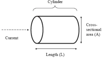
The resistance (R) of a length of homogeneous conductive material of uniform cross sectional area is proportional to its length (L) and inversely proportional to its cross sectional area (A), as illustrated in figure below.
Figure 1. Cylinder model for the relationship between impedance and geometry
Hence resistance:
R = ρL/A = ρL2
/V (1) and volume:
V = ρL2
/R (2)
where ρ is the resistivity of the conducting materials
and V equals AL. Although the body is not a uniform cylinder and its conductivity is not constant, an empirical relationship can be established between the impedance quotient (length2/R) and the volume of water, which contains electrolytes that conduct the electrical current through the body. In practice, it is easier to measure height than the conductive length, which is usually from wrist to ankle. Therefore, the empirical relationship is between lean body mass (typically 73% water) and height2/R.
Due to the inherent field in-homogeneity in the body, the term height2/R describes an equivalent cylinder, which must be matched to the real geometry by an appropriate coefficient. This coefficient depends on various factors, among them also the anatomy of the segments under investigation. Therefore, errors occur when there are alterations in resistivity of the conductive material, variations in the ratio height to conductive length, and variations in the shape of the body and body segments (body segments behave as if they are in series with each other, with shorter and thicker segments contributing less to the total R).
Figure 2. The human body consists of resistance and capacitance connected in parallel or in series
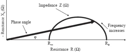
R and capacitance can all be measured over a range of frequencies (most single-frequency BIA analyzers operate at 50 kHz). At zero (or low) frequency, the current does not penetrate the cell membrane, which acts as an insulator, and therefore the current passes through the extracellular fluid, which is responsible for the measured R of the body R0. At infinite frequency (or very high frequency) the capacitor behaves as a perfect (or near perfect) capacitor, and therefore the total body R (R∞) reflects the combined of both intracellular and extracellular fluid. Since practical constraints and the occurrence of multiple dispersions prevent the use of a direct current (zero frequency) or very high frequency AC currents, the R values at the ideal measurement frequencies are predicted using a Cole–Cole plot [16] (negative reactance versus R plot), with R0 theoretically representing the R of the extracellular fluid (intracellular water) and R
representing the R of intra- and extracellular fluid (TBW), as illustrated in Figure 3.Figure 3. Diagram of the graphical derivation of the phase angle; its relationship with resistance (R), reactance (Xc), impedance
(Z) and the frequency of the applied current
The cylinder model in Figure 1 which is representation of human body, can be partitioned into several compartments as illustrated below.
Figure 4. Diagram of fat-free mass (FFM), total body water (TBW), intra-cellular water (ICW), extra-cellular water (ECW),
and body cell mass (BCM)
According to the Figure 4, human body can be divided into two major partitions, fat mass (FM) and fat-free mass (FFM). FFM is everything that is not body fat. It is mainly composed of body water and small portion of protein and mineral. This portion will be used to derive body water and body muscle percentages. Whereas FFM is everything that is not body fat, there is no consensus on the physiological meaning of measures of body cell mass (BCM). The BCM is the protein rich compartment, which is affected in catabolic states, and estimating the size is difficult because it is a complex compartment, comprising all non-adipose cells as well as the aqueous compartment of adipocytes.
BIA measurements must be standardized in order to obtain reproducible results. Reported mean coefficients of variation for within-day R measurements are
1–2%; daily or weekly intra-individual variability is slightly larger ranging from
2% to 3.5% [17 - 20].Day-to-day coefficients of variation increases for frequencies lower than 50 kHz [21]. Overall reproducibility/precision is 2.7– 4.0% [19].Prediction errors were estimated to be 3– 8% for TBW and 3.5–6% for FFM, respectively [22, 23].field of current during the measurement could alter the pacemaker or defibrillator activity.
2.2
Design and Implementation of
Bioelectrical Impedance Analyzer
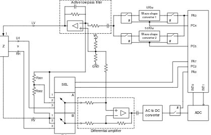
The analyzer design involves mixed circuitry, both analog and digital. Primarily, the analog circuit is used to perform signal conditioning upon bio-potential signal picked up by electrodes. The digital counterpart is used to administer signal injection to human body through electrodes and process the acquired signal from analog circuit into human readable form with the help of analog to digital converter (ADC). The block diagram of bioelectrical impedance analyzer is illustrated in Figure 5. The heart of the system is microcontroller MPC82G516A from Megawin Technology.
Wave-shape converter 2 Wave-shape converter 1 PC4 PC5 B A SEL PC2 PA7 Z v i VR2 GND
AC to DC
converter ADC IN T 0 IN T 1 PA0 PA3 LV RV LH RH R301 R302 5 Khz 50 Khz multiplexer Differential amplifier Active low pass filter
# # # # # 1 1 2 2 3 3
Figure 5. Biolectrical impedance analyzer block diagram
Although the block diagram looks complicated, the working mechanism is quite straightforward. As it is reflected from the name, the sensing target for BIA estimation is body impedance. Like the impedance in the electrical circuit, the common measurement technique is to inject a certain amount of alternating current to target impedance and measure the voltage drop due to impedance. The impedance is then simply voltage per current. This technique is also applicable to BIA estimation, with slight modification.
In this research, the method of injecting current to body and measure the voltage drop is known as tetra-polar method. Current is injected through the electrode pads under the front of each foot and the voltage measured by the electrodes under the heel. Since the aim in BIA is to measure the impedance of the deep tissues, the tetra-polar method is preferred as the voltage drop measured
using a separate set of electrodes will be that of the deep tissues, since negligible current is drawn through the electrode. The tetra-polar arrangement is illustrated in Figure 6.
LV RV LH RH Electrode pads V i v
XC RICW
RECW RC RC RC RC V i v LV RV LH RH Z
Figure 6. Four electrode pads and equivalent circuit of body impedance
A circuit model called Fricke’s circuit
[Figure 2] is used to represents body impedance. There are four additional resistors included to the model due to skin resistance. The electrode pads are made from particular conductive material deposited on glass surface.
From current stimulus perspective, this BIA circuit is categorized multi-frequency BIA means the circuit uses different frequencies to evaluate FFM, TBW, ECW, and ICW. In this research, the lower frequency is set at 5 kHz while the higher frequency is set at 50 kHz. The microcontroller is responsible for these signals generation. Timer 2 and timer 2 interrupt is used to address this task. The timer is set to auto-reload mode and appropriate reload value is assigned to timer register. Each time timer 2 overflows; the routine in timer 2 ISR alternates the state of PA3. Therefore, as long as timer 2 runs, continuous square wave signal generated and outputted to PA3.
The signal gating is governed by PC4 and
PC5. When PC4 at logic “high”, 5 kHz signal is
delivered to the system and PC5 does likewise with 50 kHz signal. The requirement for BIA circuit is sine wave signal; therefore the square wave signal should be converted using converter 1 and converter 2. These blocks have similar construction, only differ in component values. Before injected to target impedance, this signal is amplified and filtered using active low-pass filter.
ZL
vo R301
R302 C A 5/50 kHz
i ZL
vo R301
R302 C B 5/50 kHz
i
Step 1 Step 2
ZL
vo R301
R302 C
D 5/50 kHz
i
Step 3
Figure 7. Simplified BIA block diagram and measurement steps
R301 and R302 serve as reference
resistances; the value is 300 Ω and 600 Ω
respectively. The sequence is quite straightforward, and also applies both to 5 kHz and 50 kHz
impedance measurement. Firstly, the multiplexer’s
inputs are directed to measure voltage drop between two reference resistances (vAC). Secondly, the
multiplexer’s inputs are then directed to measure voltage drop between single reference resistance (vBC). Finally, to obtain the target impedance value,
the multiplexer’s inputs are directed to measure
voltage drop between target impedance (vDC). It is required to measure impedance at 50 kHz and impedance at 5 kHz. Therefore, the complete sequence to estimate body composition takes 6 steps.
The output of multiplexer is connected to the input of differential amplifier to be amplified with certain gain. Up to this stage the signal is still alternating current (ac). Therefore a circuit to get direct current (dc) equivalent is inserted in between differential amplifier and ADC. In addition, this circuit also adjusts the dc output to a certain level that is within the range of ADC input.
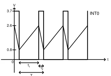
The ADC circuit doesn’t refer to embedded ADC inside Megawin MPC82G516A. Instead, it refers to external mixed circuit serves as dual-slope integrating ADC – like. The primary function of this circuit is to translate a certain level of DC input voltage to a pulse-width modulated square wave signal. Clearly, in this ADC the change of input
voltage will modulate the signal’s duty cycle. The
duty cycle is then fed to microcontroller and interpreted using particular algorithm. By doing this way, voltage information (volt) is conveyed to microcontroller in time unit (second). The
waveform fed to microcontroller’s INT0 (interrupt
port 0) is illustrated in Figure 8.
2.6
0.8
0 3.7
V
t t1
t2
T
INT0
Figure 8. Pulse-width modulated signal as representation of voltage
For this application, t2 is used to obtain the target impedance (ZL) value. The measurement concept is illustrated in Figure 9.
V (x2,y2)
(x1,y1)
0
(x3,y3) t2(us)
vac vdc vbc
t2b
t2a t2c
600 300 ZL
R(Ohm)Figure 9. Impedance measurement based on t2 reading
At first step, microcontroller obtains t2a as representation of vAC. Secondly; t2b is then obtained as representation of vBC. It is commonly understood that value of vAC is twice the value of vBC since the same current flows through those resistances. However, it is not relevant to t2a and t2b. Finally, at third step, t2c which is representation of vDC is obtained.
The first two steps are used to establish reference line. The slope of this line must be calculated using equation (3) to enable impedance measurement.
2 1
1 2
y
y
m
x
x
(3)The m in equation (3) can be also expressed using equation (4).
3 1
3 1
y
y
m
x
x
By rearranging equation (4), the actual impedance (x3) can be obtained.
3 1
3 1
y
y
x
x
m
(5)The impedance at 5 kHz and impedance at 50 kHz, along with weight, height, age, and gender information will be used to estimate body composition. The final result of this estimation is percentage of body fat (BF), total body water (TBW), and body muscle (BM) which is displayed on character liquid crystal display (LCD). The formulas are not shown due to proprietary right.
Impedance measurement at 50 kHz is used to estimate body fat and total body water while impedance measurement at 5 kHz is used to estimate body muscle. Actually, impedance measurement at 50 kHz means TBW estimation. TBW itself consists of ECW and ICW. Information about body muscle percentage is derived from ICW, meanwhile the impedance at 5 kHz only represents ECW. Therefore, ICW value must be obtained from TBW – ECW.
3
RESULT
The design considerations and implementation regarding bioelectrical impedance analyzer has been elaborated in previous sub-chapter. A prototype of the analyzer has been successfully developed and tested.
Basically there are two tests have been conducted upon the prototype to determine its reliability of impedance measures, and investigate the validity of the measurements. The purpose of the first test is to ensure that the analyzer can measure impedance of electric circuit model of human body properly. It is reasonable to assume that if BIA section shows correct result in measuring impedance of electric circuit, it will remain correct for measuring impedance of human body as well. After that, at the second test, the analyzer applied to human body to investigate its performance in the real-world application.
The circuit model for human body impedance used in the first test is Fricke’s circuit. This model is further improved by incorporating skin resistance on each terminal to simulate real application, as illustrated in Figure 6 previously. The circuit model is basically a simple RC network
with impedance Z. The value of Z can be calculated using (6).
(
C ICW) ||
ECWZ
X
R
R
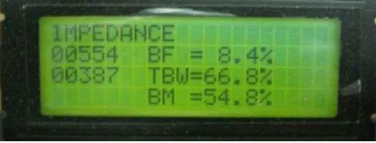
(6)In the first test, RICW = 560 Ω, RECW = 560 Ω, C = 4.7 nF, RC = 820 Ω were used. The impedance both at 5 kHz and 50 kHz were then measured. The experiment was repeated 10 times to ensure the repeatability. The BIA results (BF, TBW, and BM) were obtained by plugging in Z5kHz and Z50kHz in BIA formula inside the microcontroller. The other parameters needed to compute BIA (gender, age, height, and weight) were manually inputted. The result is based on reading of LCD screen located on front panel of the analyzer as illustrated in Figure 9.
Figure 9. LCD screen when measuring impedance in Fricke’s circuit
The result of 10 consecutive experiments is summarized in Table 1.
Table 1. Result of impedance test on Fricke’s circuit
Z5kHz(Ω) Z50kHz(Ω) BF(%) TBW(%) BM(%)
550 380 8.0 67.3 55.5
550 385 8.3 66.8 54.8
550 382 8.1 67.3 55.5
548 381 8.0 67.3 55.5
550 381 8.0 67.3 55.5
548 383 8.1 66.8 54.8
550 387 8.4 66.8 54.8
549 386 8.3 66.8 54.8
550 380 8.0 67.3 55.5
548 387 8.4 66.8 54.8
Based on hand calculation, Z5kHz and Z50kHz
equals to 554 ∟ -4o Ω and 376 ∟ -19o Ω. In average, the test result indicates Z5kHz and Z50kHz equals to 549 Ω and 383 Ω which is close to the result from hand calculation. The analyzer only measures the real part from the complex impedance while the imaginary is omitted. Based on data analysis of the first test, the impedance measurement at 5 kHz has maximum error 0.1 % while 50 kHz counterpart has 0.45%.
over a period of time. This test was conducted in 10 consecutives days. Each day, the test was conducted in two sessions, morning and evening, repeated for 10 times per session. It is assumed that during repetition, the environmental factors will not change drastically thus any variation on the result shall be caused by the internal mechanism of the system. In average, one session takes 15 minutes. On every
session, subject’s weight and height were measured
using traditional weight scale and ruler since recall values are not acceptable in BIA. A commercial product from SOEHNLE, namely Body Balance was used as reference instrument. Totally, the system has been tested at least for 200 times thus it also provides reliability information of the analyzer. According to test scheme, there are vast amount of data set that can be analyzed to evaluate the performance of the system. However, those data are not shown in this paper because of the limited space. From data analysis, it can be concluded that BF, TBW, and BM estimation has maximum error 2.82%, 0.65%, and 0.88% respectively.
4
CONCLUSION AND FUTURE
DIRECTIVES
A prototype of tetra – polar bioelectrical impedance analyzer has been designed and implemented based on Megawin 82G5126A microcontroller. The analyzer uses tetra-polar method for injecting current to body and measure the voltage drop. From current stimulus perspective, the analyzer is categorized multi-frequency BIA which uses 5 kHz as lower frequency and 50 kHz as higher frequency. Using Fricke’s circuit model, the impedance measurement at 5 kHz has maximum error 0.1 % while 50 kHz counterpart has 0.45%. A simple clinical test has been conducted as well on human body repeatedly over a period of time. From data analysis upon the tests, it can be concluded that BF, TBW, and BM estimation has maximum error 2.82%, 0.65%, and 0.88% respectively.
Thus far, the analyzer has capability of determining body composition based on bioelectrical impedance analysis. The composition which consists of body fat, body water, and body muscle are displayed on LCD in terms of percentage. This can further be improved by implementing algorithm to compare acquired body composition with a particular standard. Based on the comparison and analysis, the analyzer is then generates recommendation regarding diet and exercise for user.
REFERENCES
[1] Brozek J, Grande F, Anderson JT, Keys A (1963) Densitometric analysis of body composition: revision of some quantitative assumptions. Annals of New York Academy of Sciences l10:113-40.
[2] Panaretto BA. (1968) Estimation of body composition by the dilution of hydrogen isotopes. In: Body Composition in Animals and Man. Washington, DC: National Academy of Sciences, National Research Council, pp.200-17.
[3] Forbes GB, Hursh JB. (1963) Age and sex trends in lean body mass calculated from 40K measurements: with a note on the theoretical basis for the procedure. Annals of New York Academy of Sciences l10:255-63.
[4] Vartsky D, Ellis KJ, Cohn SH. (1979) In vivo quantification of body nitrogen by neutron capture prompt gamma-ray analysis. Journal of Nuclear Medicine 20:l158-65.
[5] Cohn SH, Shukla KK, Dombrowski CS, Fairchild RG. Design and calibration of a
“broad beam” 238
Pu, Be neutron source for total body neutron activation analysis activation analysis. Journal of Nuclear Medicine l3:487-92.
[7] Presta E, Wang J, Harrison 0G. Bjorntorp P. Harker WH, Van Itallie TB. (1983) Measurement of total body electrical conductivity: a new method for estimation of body composition. American Journal of Clinical Nutrition 37: 735-9.
[8] Lohman SG. (1981) Skinfolds and body density and their relation to body fatness: a review. Human Biology 53:181-225. [9] Haymes EM, Lundegren HM, Loomis JL,
Buskirk ER. (1976) Validity ofthe ultrasonic technique as a method of measuring subcutaneous adipose tissue. Annals of Human Biology 3:245-5 1. [10] Thomasset (1962) A. Bio-electrical
properties of tissue impedance measurements. Lyon Medical 207:l07-18. [11] Thomasset A. (1963) Bio-electrical
properties of tissues. Lyon Medical 209:1325-52.
[12] Hoffer EC, Clifton KM, Simpson DC. (1969) Correlation of wholebody impedance with total body volume. Journal of Applied Physiology 27:531–4.
[14] Boulier A, Fricker J, Thomasset A-L, Apfelbaum M. (1990) Fat-free mass estimation by the two-electrode impedance method. American Journal of Clinical Nutrition 52:581–5.
[15] Gudivaka R, Schoeller DA, Kushner RF, Bolt MJ. (1999) Single- and multifrequency models for bioelectrical impedance analysis of body water compartments. Journal of Applied Physiology 87: 1087–96.
[16] Cole KS. (1941) Dispersion and absorption in dielectrics. I. Alternating current characteristics. Journal of Chemical Physics 9:341–951.
[17] Kushner RF, Schoeller DA. (1986) Estimation of total body water by bioelectrical impedance analysis. American Journal of Clinical Nutrition 44:417–24. [18] Segal KR, Gutin B, Presta E, Wang J, Van
Itallie TB. (1985) Estimation of human body composition by electrical impedance methods: a comparative study. Journal of Applied Physiology 58:1565–71.
[19] Lukaski HC, Johnson PE, Bolonchuk WW, Lykken GL. (1985) Assessment of fat-free mass using bioelectrical impedance measurements of the human body.
American Journal of Clinical Nutrition 41:810–7.
[20] Ward LC, Byrne NM, Rutter K, et al. (1997) Reliability of multiple frequency bioelectrical impedance analysis: an intermachine comparison. American Journal Human Biology 9: 63–72.
[21] Jansen DF, Korbijn CM, Deurenberg P. (1992) Variability of body density and body impedance at different frequencies. European Journal Clinical Nutrition 46:865–71.
[22] Sun SS, Chumlea WC, Heymsfield SB, et al. (2003) Development of bioelectrical impedance analysis prediction equations for body composition with the use of a multicomponent model for use in epidemiologic surveys. American Journal of Clinical Nutrition 77:331–40.
[23] Kushner RF. (1992) Bioelectrical impedance analysis a review of principles and applications. Journal of the American College of Nutrition 11: 199–209.
