TK
5103.2 A995 1997
BORANG PENYERAHAN TEStS
.Jlldul COMPUTER RS232 WIRELESS LINK
SESI PENGAJlAN 1997/98 -=-=-:.=~
Saya AZMAN OSMAN LIM @AZMAN BIN HAJ. OSMAN
(HURUF BESAR)
MeDgaku membeoarkan le~", ini lIi.impaD tli PU,"l1 Khidmnt MAklulll11t Akad,'m.k.
Unwen!11I Malay ... Sara....k dO'>g8n .yaral-"yara! kcgunnan ""port! berikut:
1. Hakmlhk kert8B projek adalah ct. lJuw.b nama IX'nuJi. m('lmnkon ponul"",n ""bugai proWk bersama daD dilJ"'YHI olch UNIMAS, hakmlhknyll "do"'h knpunyann UNIMAS. 2. N.8khah salirum dJ dalam bentuk kOrtH" "LIIu mikro Iull1Y8 bol~h dib""1 dl'ngon
kebellllro" ""rtult. daripada penuli •.
3. PUM! Khidmat Maklumal Ak.dmnik, UNIMAS di"""",kan mpmbunl ."Iilllln \l muk pengajian IM ....k • .
4. Kerl.s pro...,k h.nyo lloleh diterbitknn dengon keoona'"" penuh~. Baya,"n royoUi ad"lah menwku! kadar yang dipetlll'tuJui kelnk.
6, • Saya membena,kanllidak memlH'nu,luJn Porn",!"kaun momb,,"! ""IIDan kprt... projek tI1J. ,;(lhagoi baban pertukanm di antara inslitus. J)<lngaJlan lInggl,
6, •• Sila !8ooakau (./ )
C:=:J
SULIT (Mellgondullgi mnklUlllJl1 yung berdmjl1h kp'ela"",'nn IIlou kepenllngaJl Malay la ...pertl yang !ermaklUb dl ualam A!ITA RAHSIA RASMI 1972)C:=:J
TERIIAD (Mangnndungi ma.klurnol TERHAD yang t~lnh d.t~ntukon olehorgonisasilbadBn dl ma"" \l<.nyt'lidikBn dijalallkan).[2J
TIDAK TERIIADDI88bl<an oleb
f
J..
(TA1{DATANCAN PENULL.'>l (I'ANDA'~1 ;AN PENYELlA)
N(.
Lt,r,.,v{
~Aloma! laUlp No.St, Ambar Park
4-
(Jet{'?if?
Jalan Kuhara
91000 Tawau Nama PenyelJa
Sabab
APPR
O
VAL SHEET
This project report attached hereto, entitle "(;{)mputeT RS232 Wireless Link" prepared and submitted by Azman Osman Lim @ Azman BiD Haji Osman in partial fllifillment of the requirements for th degree of Bachelor with honours ofEIe<:tronica and Tete<:ommunicationa Engineering is hereby accepted.
DElt(l:_---.:.Jf_ tJ_c.J " _
__~
f!/n-
__
Faculty of Engineering U nivel'1liti Malaysia Sarawak Le<:turer
,
1
P. K H IDI"I ,oIlT M AK LUI"I A T
m~~11
J
~n]
(
~ll!.
COMPUTER
RS232WIRELESS LINK
AZMAN OSMAN L1M@AZMAN BIN HAJl OSMAN
Tesi.s Dikemukakan Kepada
Fakulti Kejuruteraan, niveraiti Malaysia Sarawak Sebagai Memenuhi Sebahagiaan Daripada Syarat
Penganugerahan Sarjana Muda Kejuruteraan
DengaD Kepujian (Kejuruteraan Elektronik dan Telekomunikasi)
To all my loving family and relatives
ACKNOWLEDGEMENT
The author wishes to express his sincere appreciation and !rratitude to his supervisor, Mr. Ng Liang Yew, for his invaluable guidance, suggestioO$ and constructive criticialDJ:l throughout the course of this study.
A sign of gratitude is also forwarded to the Dean of the Faculty of Engineering,
Assoc.
Prof. Dr Khairuddin Bin Abdul Hamid and the HeadProgramme of Electronics and TelecommunicatioO$, Dr. Mohamad Kadim Bin
Suaidi
The author aOO likes to render his sincere thanks to En. Wan Abu Bakar gah for his support, assistant and cooperation in carrying out the project.
Not forgetting, to aU my friends who have heen very helpful, and generous in contributing towards the success of this project.
Last but not least, the author would like to take this opportunity t~ express his special thanks, gratitude and appreciation to Jus parents for their financial support and encouragement throughout his studies in UNIMAS.
ABSTRACT
A new approach in a wireless communication link. which aUow8 two or
more computers to communicate with each other via their RS232 interface8. is
described. This discussion includes detail on the concept and practical of the
RS232 interface standard. general system process, hardware description. data
communication protocol. radio frequency modulation methods. radio frequency
transmission methods and antenna to develop the project. Recommendations of
the project are also provided in this paper such that further improvement can be done. This project is to design a transceiver module. which uses a wireless
communication link via RS232 interface.
A BSTRAK
Perbincangao mengenai satu pendekatan barn dalam suatu perhubungan
komunikasi tanpa wayar yang menggunakan dua atau lebih daripada
komputer untuk berkomunikaai 8eaama sendin melalui Buatu perantaraan RS232. JusteN itu, perbincangan ini berkenaan konsep dan praktikal agar dapat membantu dalam menghaailkan 8uatu projek reksbentuk termasuk piawai peraotaraan RS232, proses sletem umum, penerangan perkakasan,
proloko\ data komunikasi. kaedah pemoduletan frekuenai radio, kaedah penghantaran frekuenei radJo, dan antena. Di ssmping itu, cadangan·cadangan mengenai projek ini dieertakan bersama dalam perbincangan kertas ini agar projek ini dapat dJperbaiki. Pada hakikatnya, projek ini adalah untuk menghasilkan atu reksbentuk urut pengbantar-terima yang mengaplikasikan perhubungan tanpa wayar melalui perantaraan RS232.
TABLE OF CONTENTS Co,i.lents DEDICATION ACKNOWLEDGEMENT ABSTRACT ABSTRAK TABLE OF CONTENTS LIST OF TABLES LIST OF ILLUSTRATIONS 1.0 INTRODUCTION
2.0 THE RS232 INTERFACE STANDARD 2.1 Overview
2.2 Role otthe RS232 Interface Standard 2.3 RS232 Operation
2.3.1 Sigrw/ Levels 2.3.2 Sig,1Ol Li'lell
2.3.3 Signal States and Bit Timillg
2.4 RS232 interfacing
2.5 The Computer RS232 Interrace Standard Vl Page u ill IV V VI Xl xiii 1 3 3 5 7 8 9 12 18 19
2.6 Connecting RS232 Interface Standard
Devices 22
2.7 Computer Equipment Interface 24 2.7.1 Typical Computer Equipment Illterface 24
2.7.2 USARTs 27
2.7..'1 Baud Rate 30
2. 7.4 Types of USARTs 30
2. 7.51mprOlJemellt OIl Computer Equipment
lrlterface 31
2.8 Impact of RS232 Int~rface Standard OD
Performance 31
2.9 Advantages of Serial RS232 Interface
Standard 33
2.10 Limitation of RS232 Interface Standard 34
3.0 GENERAL SYSTEM PROCESS 36
3.1 Software Configurations 36
3.1.1 Disk OperatinB System (DOS) COIlfiBuration 36 3.1.2 Basic lrlput output System (BIOS)
COllfllfuration 37
3.1.3 Register Confisuration 38
3.2 Communicating in Serial Data 38
3.3 Flow Control 38
3.4 DTElDCE Speeds 39
3.5 Programming 39
3.5.5 Determining the Type of USART via Software 45
4.0 HARDWARE DESCRIPTION 46
4.1 Physica] RS232 Connectors and Cables 46
4.2 Computer Port Con6guratlons 47
4.2.1 Serial Port Registers 47
4.2.2 COM Port Base .4ddres6eS 49
4.3 External Hardware Interfacing Methods 50
4.3.1 RS232 Waveforms 50
4.3.2 RS232 Level Corwertes 52
4.3.3 Microcontrollers 53
5.0 DATA COMMUNICATIONS PROTOCOLS 55
5.1 Overview 55
6.2 Character Oriented DLC Protocols - Bisync 56
5.2.1 Normal Text Transmission ill Bisync 58
5.2.2 Transmission of Trallsparent Te.:a 60
5.2.3 Control ofAccess to DoIa Lill.k 61
5.2." Limitations ofBisync 64 6.0 RF MODULATION METHODS 66 6.1 What is Modulation! 66 6.2 Frequency Modulation (FM) 66 6.3 FSK Modulation 68 6.3.1 FSK Transmitter 69 6.3.2 Bandwidth Considerations of FSK 71 6.3.3 FSK Receiver 74 viii
6.3.4 Minimum Sllift·KeyiJIg FSK 75
6.3.5 Limitation ofFSK 77
6.4 FSK Implementations 77
6.4.1
xeo
Modulation 776.4.2 Modulotioll by Switchinf! between Diuiders 79
6.4.3
veo
Modulation 797.0 RF TRANSMISSION METHODS 80
7.1 Overview of RF Transmission 80
7.2 Spread Spectrum Background 81
7.3 Spread Spectrum Methodology 82
7.4 Understanding Spread Spectrum Tecbnology 83
7.4.1 Direct Sequence Spread Spectrum 86
7.4.2 FrequellCY Hopping Spread Spectrum 90
8.0 ANTENNA 92
8.1 Overview 92
8.2 Radio Wave Propagation 92
8.3 Fundamental of Radio Antennas 94
8.4 Types of UHF Antennas 95
8.4.1 Long Wire (Whip) A,uennos 95
8.4.2 Loop Antennas 95
8.4.3 Antell/IO Arrays (Yogi Alltl!ll/lOB) 96
98
9.1 Features of Transceiver Module
9.2 General Functional Description 98
9.3 Pin Description orthe Transceiver Module 99
9.4 Technical Specification
101
9.5 RS232 Radio Link Hardware
103
9.6 Antenna Requirements
103
9.7 Mechanical Details
104
9.8 Circuit Block Diagrams
107
10.0 CONCLUSION AND RECOMMENDATIONS 111
APPENDIX A Sample Communications Program
(1024 Byte Butter Version) 113
APPENDIX B Sample Communications Program
(Polled Version) ) 15
APPENDIX C Bessel Functions Chart 117
REFERENCES 118
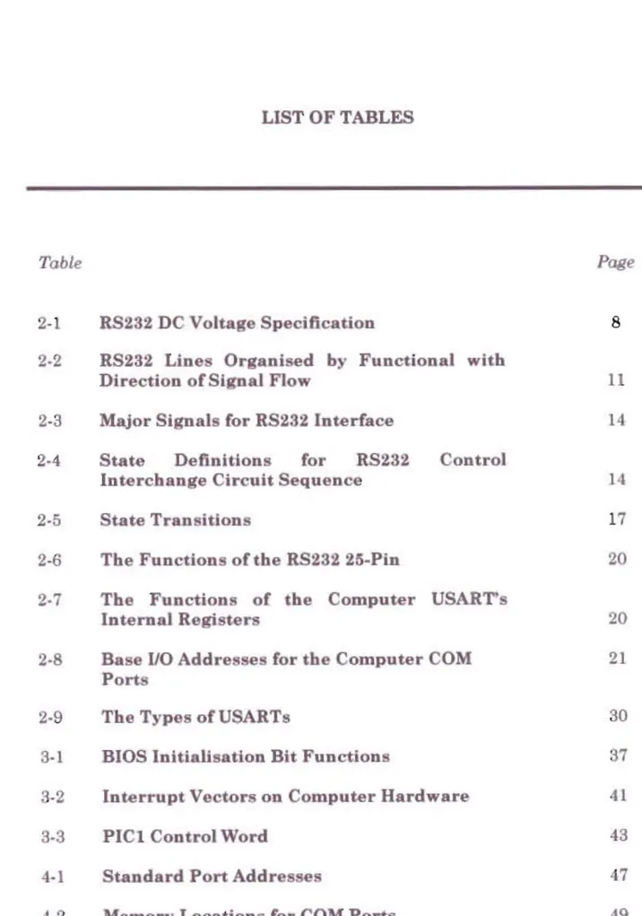
LIST OF TABLES
Table
Page
2-1 RS232 DC Voltage Specification 8
2-2 RS232 Lines Organised by Functional witb
Direction of Signal Flow 11
2-3 Major Signals for RS232 Interface 14 2-4 State Definitions for RS232 Control
Interchange Circuit Sequence 14
2-5 State Transitions 17
2-6 The Functions olthe RS232 25·Ptn
20
2-7 The Functions of the Computer USART's
Internal Registers
20
2-8 Base 1/0 Addresses for the Computer COM 21
Ports
2-9 The Types of USARTs 30
3-\ BIOS Initialisation Bit Functions
37
3-2 Interrupt Vectors on Computer Hardware 41
3-3 PICl Control Word 43
5-1 ASCII Communication Control Characters
and Their Meanings 57
8-1 Radio Frequency Bands 93
9-1 TXIRX Select Configuration of the Module
lOt
9-2 Absolute Maximum Ratings to}
9-3 Technlca1 Specifications 102
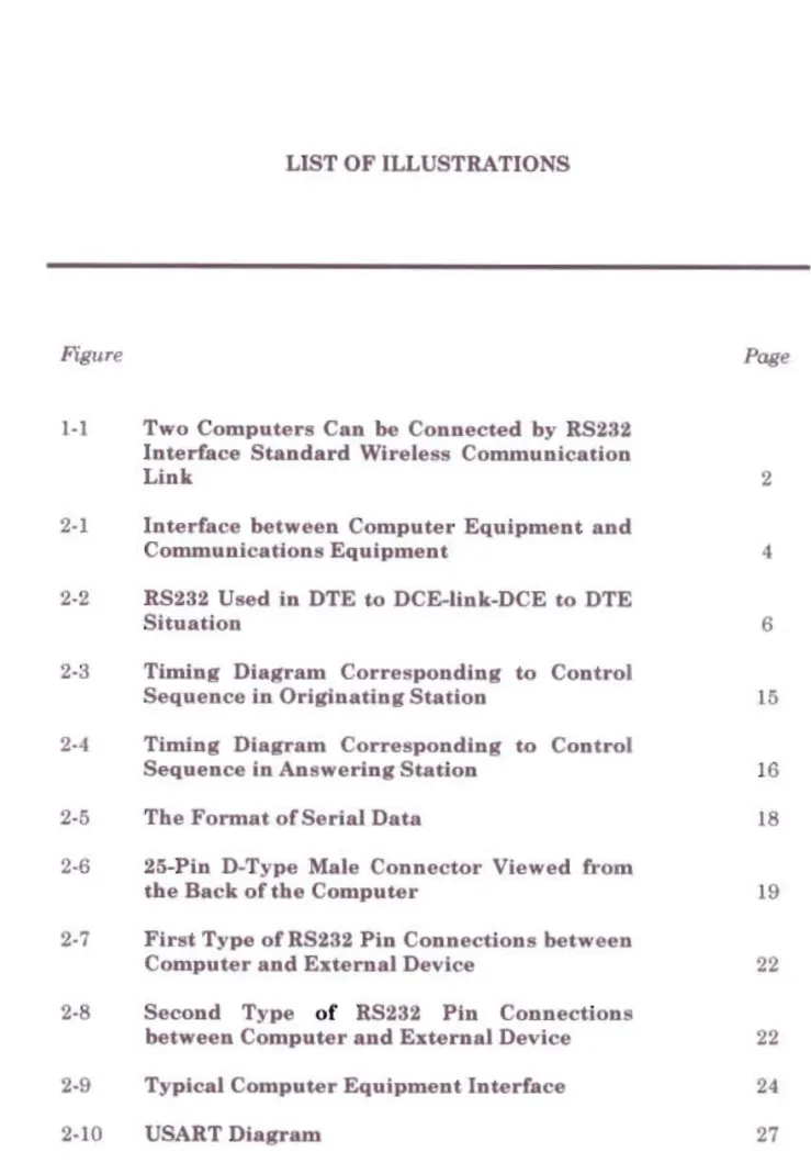
LIST OF ILLUSTRATIONS
Figure Page
1·1 Two Computers Can be Connected by RS232 Interface Standard Wireless CODlDlunication
Link 2
2·1 Interface between Computer Equipment and
Communications Equipment 4
2·2 RS232 Used in DTE to DCE-Unk-DCE to DTE Situation
2·3 Timing Diagram Corresponding Sequence in Originating Station
to
2·4 Timing Diagram Corresponding Sequence in An wering Station
to
2·5 The Format of Serial Data
6
Control 15 Control 16 18 2·6 25-Pin D-Type Male Connector Viewed fromthe Back of the Computer 19
2·7
First Type of RS232 Pin Connections betweenComputer and External Device 22
2
·8
Second Type of RS232 Pin Connectionbetween Computer and External Device 22
4-2 TTL Serial Logic Waveform 50
4-3 RS232 Logic Waveform 52
4-4 Typical RS232 Level Converters circuit,
RS232 DriverlReceiver 52
5-1 ASCII Character Set 56
5-2 The Format of Typical Bisync Text Frame 58
5-3 Typical Supervised Mode Bisync
Transmissions 63
6-1 Binary FSK Transmitter
70
6-2 FSK Modulator 71
6-3 PLL-FSK Demodulator 74
6-4 Noncontinuous FSK Waveform
76
6-5 Continuous Phase MSK Waveform
76
6-6 Crystal 0 cillator
78
7-1 Narrow Band versus Spread Spectrum
Modulation 85
7-2 Direct Sequence Spreading
87
7-3 The Operation of Direct Sequence Spread
Spectrum 88
7-4 Near-Far Effect Illustrated 9
7-5 Frequency Hopping Spread Spectrum 90
8-1 Long Wire (Whip) Antenna 95
8-2 Loop Antenna 96
8-3 Ant.enna Array (Vagi Antenna)
96
8-4 Helical Antenna 97
9-1 Tran celver Module and Helical Antenna in
Mechanical 104
9-2 PCB Board In Mechanical 105
9-3 Wireless Data Transceiver in Mechanical 106
9-4 Power Supply Circuit 107
9-5 FSK Transmitter Circuit 107 9-6 FSK Receiver U ing PLL 108
9-7 Transceiver Module 109
9-8 Transceiver Module is Connected to Power
CHAPTER 1
INTRODUCTION
Wireless communicatiollJl are nothing new. Since the early days of civilisation, various forms of communication took place without the advantage of physical connectivity. such a drull1Jl, smoke signals, semaphore flag, and light beams were used for short haul communicatiollJl. Aa radio based systems
were being introduced, wireless commurucations become more available and easier to use. In radio transmission, firstly, human voice must be converted to an electrical signal. This signal is analogous to the composition of the sound pressure changes produced by the human voice. The analysis of sound waves is a key part of radio communication theory. These radio communications principles are the basic knowledge to understanding how the various wireless communication techniques function. In early telecommunications systems, radio was an integral part of network development. Aa nl"wer systems were
introduced, enhanceml"nts and modifications enabled networks to carry all form of communication, including data, fax, image, telegraph, voice, and video.
urrentiy. wire!e technology is one of the largest growing areas of the data communications field. ]n wireless technology, many systems have been improved and modified to achieve high performance, which are compatible to
data communication llllk. Clearly. a new approach of a wireless communication
link, which allows two or more computers to communicate with each other via
their RS232 interfaces. is introduced. The main purpose of this project is to establi.sh wireless communication technology into a new data communication via RS232 interfaces. A circuit design on the transceiver module via RS232 interface should be accompli.shed. Hence. this paper prepares a platform of basic theory and information on wireless communication via computer RS232 interfaces.
In transceiver, the system consists of a number of .dentLca1 radio tralUJmitter or receiver unite; each connected to the RS232 interface of the various computers and can be configured as a tralUJmitter or a receiver. When it
is configured 88 a transmitter, serial data from RS232 interface is Frequ.ency
Shift Keyillg (FSK) modulated by an Ultra High Frequency (UHF) radio signal, and is transmitted to the surroundings. [f it is configured receiver. radio signals picked up by the antenna are FSK demodulated. This FSK demodulated data become a senal data and fed into the RS232 interface. This system may include
one master unit and severa] slave units. By using appropriate software. data tralUJmiasion can be achieved between the master unit and other units. (See
Figure 1-1)
CHAPTER 2
THE RS232 INTERFACE STANDARD
2.1 Overview
The RS232 physical layer interface standard was published in 1960. The new form RS232C was established nine years later for a standard plug lind protocol convention between modemB lind computers. Th 25-pin plug used for this interface hilS become almost as universal as the standard cord UBed for electrical power. This RS232 physical layer interface standard is also known a8 V.24 interface in other countries.
RS is stand for "Recommended Standard". However. the term "interface"
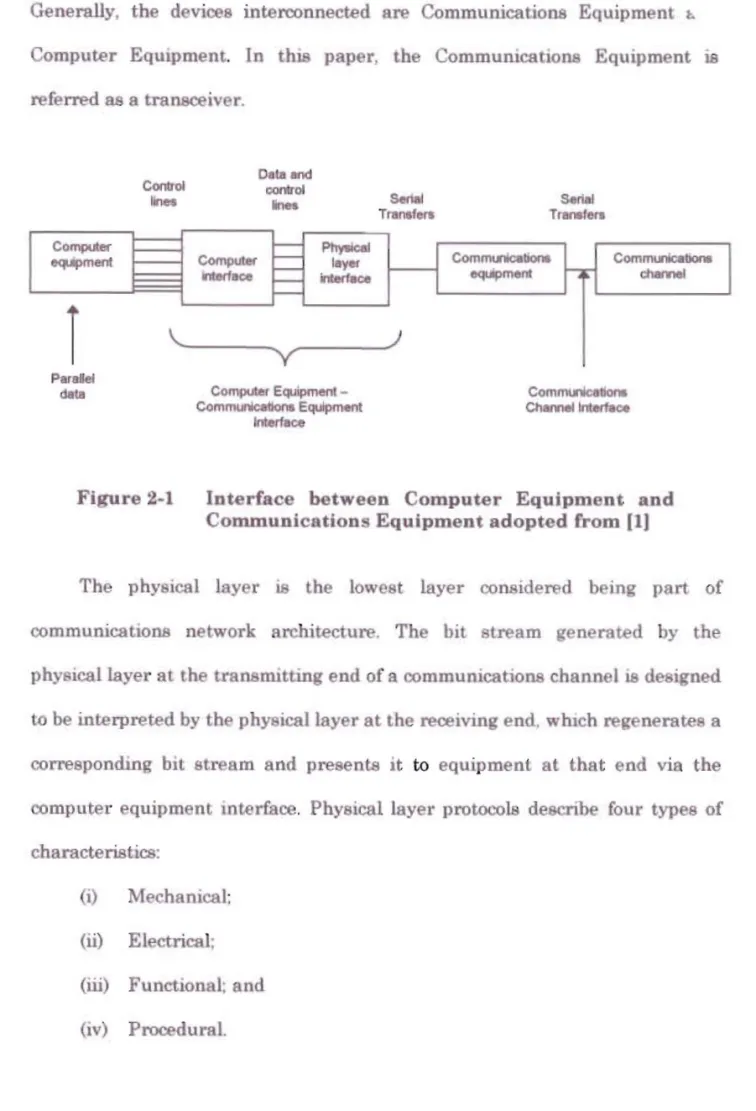
describes a boundary between two pieces of equipment aCl'088 which messages flow. In analogue or digital communications, the state of a modem or transceiver must be controlled by equipment at the node to which it is attached; an electrical or physical interface performs this function, with protocols to accomplish it. Major design problemB addressed in the interfaces include resolving incompatibilities of equipment, and co-ordination of transmitter lind receiver. As Figure 2·1 below mdicates when data lire received from a communication link, serial data mixed with control information come into a physical layer interface from communications equipment, and the same type of data are sent to communications equipment when data are tranBmittad.
Generally, the devices interconnected are Communications Equjpmenl h Computer Equipment. In this paper, the Communications Equipment is referred as a transceiver. Data ond Co.".,... _men! CommulkJabui.
'-Computer --COOIrOI Inea ~ ~ ~ ~'--y
PhyoicaI loyer irUtfaoo Compute< Equipment -Communlcatlono Equipment Seriol T... Comrn<ncatio.-. equipment -: ) en..r
Parallel data ~Figure 2-1 Interface between Computer Equipment and
Communications Equipment adopted Crom 11)
The physical layer 18 the lowest layer colUlidered being part of commumcatioDB network architecture. The bit stream generated by the
physica11ayer at the transmjtting end of a communications channel 18 designed
to be interpreted by the physical layer at the receiving end. wluch reg nerates a corresponding bit stream and presents it to equipment at that end via the computer equipment interface. Physical layer protocols describe four types of characteriBtics:
(i) Mechanical: (ii) Electrical;
Mechanical characteristics include physical dimensions of plugs or connectors, asaignment of circuits to pins, connector latchmg and mounting arrangements, and 80 forth. Such characteristics make it physically p088ible to interconnect equipment. Electrical characteristics include voltages or current levels, timings of signals, and their interpretations ae zeros or ones. They
ensure that electrical levels are compatible. Timings include pulse rille times and durations and largely determine tranBmi.saion speeds. Functional specifications 888Lgn meanings to circuits (or pins). It is common to cla88Uy CIrCuits into categones of data, control, timing, and grounds. Voltage pulses corresponding to ones and zeros represent dala, control, and timing signals. Finally, procedural specifications indicate sequences of control and data
messages to set up, use, and deactivate physical level connections. Both ends must agree upon such sequences if data transfers are to be intelligible. II]
2.2 Role ofthe RS232 InUlrface Standard
Electronic Industrie8 Association (ElA) standard for RS232 is one of the
most common standards is used for low to moderate performance. RS232 is designed as the standard specification between two type of equipment that is
Dola Termill.al Equipme,tt (DTE) and Data CommunicatioTt8 Equipme'tt (DCE).
(See Figure 2.2)
DTE describes the interface equipment used at the stations to adapt the
digital signaLs from the computers and terminals to a form more suitable for
transmission. However, DeE is described as the transceIVer that converts digital signa to analogue signals and interfaces the DTE to the analogue
SigJwI on link
..n.n..n..
..n.n..n..
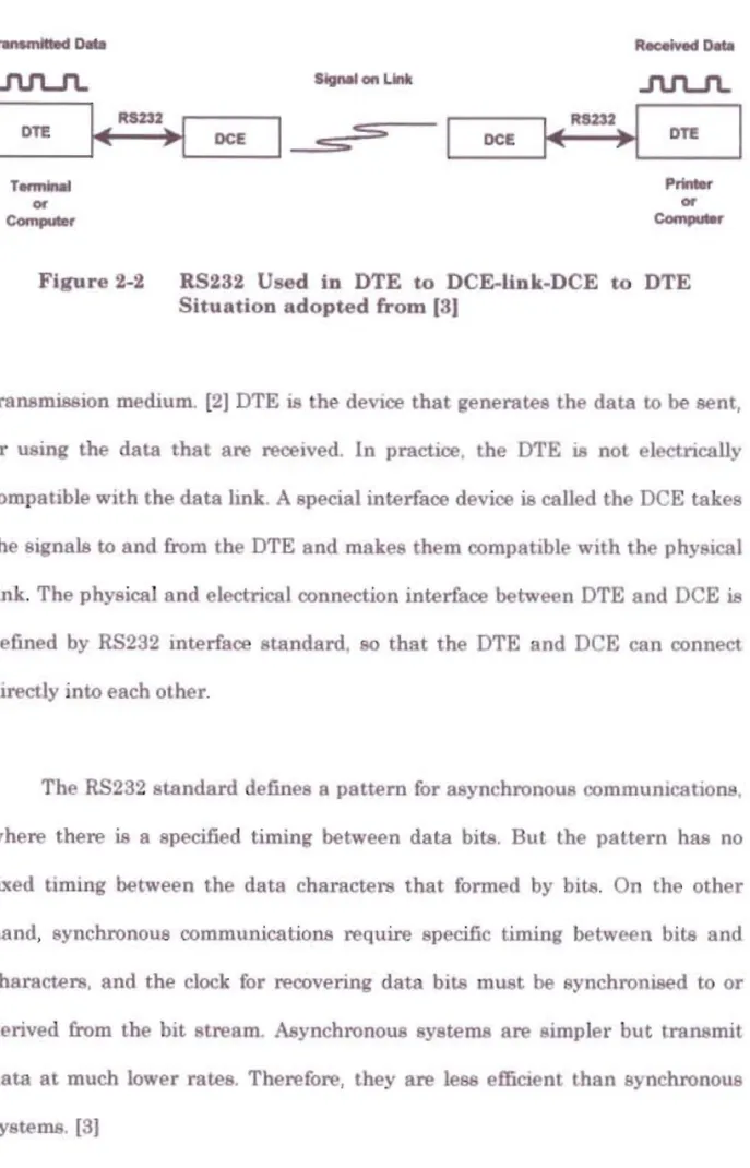
Tonnlnaf Printer 01' 0< c:ornpu., Com...Figure 2-2 RS232 Used in DTE to DCE-Unk-DCE to DTE
Situation adopted from (3)
transmission medIUm. [2] DTE is the deVlce that generates the data to be sent,
or using the data that are received. 1n practice. the DTE is not electrically compatible with the data link. A special interface device is called the DCE takes the signals to and from the DTE and makes them compatible with the physical
link. The physical and electrical connection interface between DTE and DCE is
defined by RS232 interface standard. 80 that the DTE and DCE can connect
directly into each other.
The RS232 standard defines a pattern for asynchronous commuIDcatiollB.
where there is a specified timing between data bite. But the pattern has no
fixed timing between the data characters that formed by bite. On the other hand. synchronous communications require specific timing between bits and characters. and the clock for recovering data bite must be synchronised to or
derived from the bit tream. Asynchronous ystems are simpler but transmit
data at much lower rates. Therefore, they are less effiClenL than synchronous