Prediction of Turning Performance in
Various Machining Parameter Using FEM
Hendri Yanda, Jaharah A. Ghani, Che Hassan Che Harun Department of Mechanics and Materials
Universiti Kebangsaan Malaysia
43600 UKM Bangi, Selangor Darul Ehsan, Malaysia
Abstract - In recent years, the applications of finite element method (FEM) in metal cutting operations have proved to be effective in studying the cutting process and manufacturing process. The simulation result is useful for both researchers and tool makers to optimize the cutting process by designing new tools. Simulation and modelling were performed in two-dimensional and three-dimensional for designing the new component prior to fabricating. These are very useful for reducing time and cost consumption in designing automotive parts. The FEM simulation just only requires computational tool and FEM simulation package. The present work aims to predict of performance three-dimensional orthogonal of cutting operations using FEM software (Deform-3D). Some important information such as cutting force, stress, strain and generated temperature during machining process were studied and analysed. Orthogonal cutting simulations were conducted to study the effect of cutting speed, feed rate and depth of cut on the cutting force, the effective-stress, strain and generated temperature in turning process. FCD 500 (ductile cast iron) was used as the work material and cutting tool was DNMA 432 (uncoated carbide tool, SCEA = 0; BR = -5; SR = -5 and radius angle 55o). The cutting parameters varied were cutting speed (100 m/min, 150 m/min and 200 m/min), feed rate (0.1, 0.25 and 0.4 mm/rev), and depth of cut (DOC) (0.3, 0.6 and 0.9 mm). The performance was showed by the simulation results that show by increasing the cutting speed, it causes decreasing in cutting force, effective stress and strain, but the generated temperature during the chip formation process increases. High value of feed rate resulted in bigger cutting force, stress, strain and generated temperature. In addition, bigger cutting force and high generated temperature occurred at high depth of cut.
Key Words: finite element method, three-dimensional of orthogonal cutting, stress and strain, generated temperature
I. INTRODUCTION
In the field of machine building, the term of machining means removal of material from a raw material (work piece), by cutting small chips, in order to obtain the desired shape and dimensions for final part using cutting tool. Most of automotive components
have manufactured using the machining process, like turning, drilling, shaping and planning, milling, grinding, sawing, etc. Machining is the most widespread metal shaping process in mechanical manufacturing industry. Worldwide investment in metal-machining machine tools holds steady or continues to increase year by year. In machining processes, the conditions for optimal cutting are not easy to find, because a great many experiments are first to be made for the numerous specific cutting cases. Testing is very expensive, on the other hand, tests that are made in unknown conditions are difficult and risky, and the vibrations that occur in the machine tool can cause the tool to break. For solving that problem, the modelling and simulation is the best way as replacement of that experiment.
Final Element Modelling (FEM) and Finite Element Analysis (FEA) can be run by specialized programs in finite element modelling. Some authors have used their own programs in their research, others turned to commercial programs. Currently, the world knows a large variety of specialized programs such as Abaqus, AdvantEdge, Ansys, Deform, MSc Marc, etc. In this research, the simulation will be developed especially for modeling of orthogonal cutting in turning processes by using Deform-3D. The material chosen for work peace in this work is grey cast iron that is and carbide insert is chosen as its tool cutting. The cast iron was be applied in this research. Cast iron has many advantages and a lot of application in human life, used in critical
automotive components, variety of tool, tool
machineries framework, building, bridge, electronic part, gymnastic tools, fence, gate, trellis, jewelleries, etc. Beside, cast Iron is also cheap in price, and invaluable constructional material. This research aims to study the effect of cutting speed, feed rate, and depth of cut (DOC) on cutting force, stress, and temperature on turning cast iron.
II.LITERATURE REVIEW
2.1. Industrial Acceptance of Machining Simulation
2
competitive world economy requires that, for an industry to survive, it must minimize response times and costs, as well as maximize the efficiency and quality in producing a product. Simulation application of tool carbide in turning machining as shown in Fig.1 has large used in machining world.
(a) (b)
Figure 1 a). Turning process, b). Tool cutting carbide inset
Industrial acceptance of machining simulation and tool stress analysis has increased rapidly during recent years. Numerous academic examples of machining simulation have been published during the past two decades. Industrial examples have also become common place as the technology continues to spread. The growth of simulation technology in metal machining industries has come at a time when computer hardware has experienced dramatic price reduction and speed increases lasting well. Improved graphical user interfaces in commercial codes have made this technology very easy to use. The ability to analyze complex three-dimensional processes has opened up additional avenues for the application of simulation.
While Deform -3D provides sophisticated analysis capabilities, the graphical user interface is intuitive and easy to learn. Moreover, it provides utilities to
manipulate 3D geometry, including Boolean
capabilities to trim flash. Shearing and trimming operations can also be analyzed using the FEM engine. Even complex machining operations can be modelled. Deform-3D is the foundation for a comprehensive modelling system that integrates raw material production, forming, heat treatment and machining. Deform-3D continues the tradition of accuracy and state-of-the-art capabilities established in the early 1980’s. Scientific Forming Technologies Corporation has the experience and background to provide unparalleled training and technical support [1].
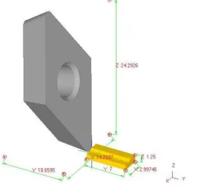
Fig. 2 shows the example of simulation model, basic cutting parameters defined and mesh overview that was performed by Deform-3D.
Figure 2. Simulation model and basic cutting parameters defined.
2.2.Finite Element Analysis with Deform-3D
Finite Element Analysis (FEA) technique was the first introduced in 1960s and still widely used for analysis such as in tools design and forming processes. Based on the success of FEM simulations for bulk forming processes, many researchers developed their own FEM codes to analyze metal cutting processes during the early 1980s up to now [2], [3], [4], [5], [6], [7], and[8]. Reference [3] assumed a rigid sharp tool and elasto-plastic workpiece, and defined a node separation criterion based on the geometry of the element approaching the cutting edge. Reference [3] used an early version of a commercial implicit FEM code “Deform-2DTM”. This code uses four-node quadrilateral elements and is based on static Lagrangian formulation.
Deform-3D is a powerful process simulation system designed to analyze the three-dimensional (3D) flow of complex metal forming processes. Deform -3D is a practical and efficient tool to predict the material flow in industrial forming operations without the cost and delay of shop trials. Today, Deform-3D™ code is commonly used by researchers and industry in machining simulation. The simulation engine is capable of predicting large deformation material flow and thermal behaviour with astonishing precision [1].
Many of research on machining or chip formation have done recently years. Based on [9], the cutting force and feed force increase with increasing feed, tool edge radius, negative rake angle, and workpiece hardness. Cutting force and feed force also increased linearly while the depth of cut was increased.
The maximum temperature of chip are increasing with increasing cutting speed. This is due to the increase of required energy for increasing the cutting processes [3].
More heat will be generated as increasing of cutting speed, consequetly the maximum temperature on the tool and workpiece surface increase at higher cuting speed. This is very probable to occur because the most of heat or generated temperature is carried away by the chip [10].
According to [11], the effect of cutting speed is almost negligible as compared to feed rate and depth of cut on the tool life of the carbide cutting tool. ANOVA analysis shows that the feed rate and depth of cut will greatly influence the generated cutting force which contributed about 98% to the generated cutting force.
III METHODOLOGY
A. Orthogonal Cutting Condition Model
workpiece. The machining parameters were varied in cutting speeds of 100, 150 and 200 m/min, feed rate of 0.1, 0.25 and 0.4, and depth of cut of 0.3, 0.6 and 0.9. Fig. 3 shows the schematic of orthogonal cutting condition model.
Figure. 3 Schematic of orthogonal cutting condition model
The commercial software Deform-3D for
deformation analysis was used to simulate orthogonal metal cutting process. It is based on an updated Lagrangian Formulation and employs an implicit integration scheme.
B. Parameter Inputs and Cutting Conditions
The three-dimensional finite element model was generated under a plane strain assumption because the width of cut was larger than the undeformed chip thickness in this orthogonal cutting arrangement. Physical and thermo-mechanical properties of the workpiece and tool materials, and cutting conditions are predefined are shown in Table 1. Mathematical expression for material constitutive model in deciding flow stress data was used Oxley model [12] as shown in : material in this study because it has been widely used in automotive application. The tool was modelled as a rigid body, so there were no mechanical properties need to be assigned and only thermal properties were needed. The cutting condition to the simulation models and the mechanical properties of carbide cutting tool and workepiece are shown in Table2. The tool was defined to be a rigid body which considers thermal transfer for modelling the cutting temperature field.
Deform-3D software had been used to simulate the effect of tool cutting geometries in turning ductile cast iron using uncoated carbide cutting tool. The simulations were performed by changing the machining parameters with combinations cutting speeds of 100, 150 and 200 m/min, feed rate of 0.1, 0.25 and 0.4, and depth of cut of 0.3, 0.6 and 0.9 as given in Table 1.
TABLE. 1
PARAMETER INPUT IN SIMULATION PROCESSES
TABLE 2
CUTTING CONDITION AND MATERIAL PROPERTIES
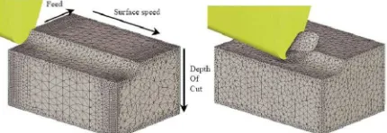
The simulation results of cutting force, effective-stress, strain and chip temperature on the cutting were studied and analyzed. The operation was simulated using insert carbide of DNMA 432 type that has a nose angle of 55 deg and without the use of coolant. Displacement, shape and surface mesh of the tool and workpiece at the initial mesh of beginning the cutting operation was developed until chip formation reach step 100 as illustrated in Fig. 4a , 4b, 4c and 4d respectively.
Figure 4. (a) Initial mesh and tool indentation, (b) Chip formation at step 25, (c) Chip formation at step 50, (d) Developed continues chip
at step 100.
The workpiece and the tool were characteristized by non uniform mesh distribution in the simulation. Very small element was required in the contact area between tool and workpiece because of very large temperature
Modulus Young (GPa) 650
Thermal Expansion 5e-06
Poison Ratio 0.25
Boundary Condition Initial Temperature (oC) Shear friction factor Heat transfer coefficient at the workpiece tool interface (N/s mm°C)
20 Workpiece properties (FCD 500; Poisson’s ratio, 0.275)
Modulus of elasticity (kN/mm2) 169
Thermal Conductivity (W/m. °C) 35.2
Thermal expansion Coefficient (· 10-6 °C-1) 12.5
Ambient Temperature (°C ) 20
Heat capacity (N/mm2 ° C) 3.7
4
during the simulation. Figure. 5 shows an example of simulation result of effective stress and temperature for cutting speed of 200 m/min at 200 steps of simulation running on chip formation.
Figure 5. One example of the simulation result effective stress and temperature for cutting speed of 200 m/min (for running in
300 step)
IV. DISCUSSIONOF RESULTS
The cutting force, effective stress, strains and chip temperature at various cutting speed, feed rate and depth of cut were studied, analyzed and discussed. The results for each simulation for varied cutting speed, feed rate and depth of cut can be seen in Table. 3.
TABLE 3
VARIOUS CUTTING PARAMETER AS INPUT AND SIMULATION RESULTS
Cutting speed w as varied; feed rate and DOC w ere kept constant
No
Feed rat e w as varied; cutting speed and DOC w ere kept constant
No
DOC w ere w as varied; cutting speed and Feed rate w ere kept constant
No
Effect of Cutting Speed
From Fig. 6 to 9 can be seen the result of cutting force, effective stress, effective strains and chip temperature at various cutting speeds. The cutting speeds were varied at 100, 150 and 200 m/min.
Figure 6 shows that by the increasing of the cutting speed, it will decrease the cutting force. This is agreeable with theory that by the increasing of cutting
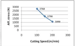
speed will soften the material, therefore this will make material easier to cut in higher cutting speed condition. Figure 7 shows that by increasing the cutting speed also will reduce the effective-stress. Increase of cutting speed from 100 m/min to 200 m/min will reduce the effective-stress from 2760 MPa to 1090 MPa. This is also agreeable with theory that gives formula:
σ = F/A (2)
Where σ = stress, F as cutting force and A is area, stress and cutting force are positif corelation, if cutting force increase so stress also will increase.
The good result were get for the graph of temperature where the increasing of cutting speed will increase the generated temperature on chip as given in Fig. 8. This is agreeable with finding from [3] where the maximum temperature of chip are increasing with increasing cutting speed. This is due to the increase of required energy for increasing the cutting processes. More heat will be generated as increasing of cutting speed, consequetly the maximum temperature on the tool and workpiece surface increase at higher cuting speed.
Figure 6. The graph of cutting speed vs Cutting force
Figure 7. The graph of cutting speed vs aff. stress
As given in the Fig. 9, the increase of cutting speed from 100 m/min to 200 m/min lead to an increase of chip temperature from 880oC to 1130oC. This is very probable to occur because the most of heat or generated temperature is carried away by the chip. The theory also tell that during machining by cutting, it is assumed that all the cutting energy is converted to heat and, therefore, a considerable amount of heat is generated at the following three distinch zones as given Fig.10, those are 1). Shear zone (75%); 2). Chip sliding on the tool face (20%); c). Tool sliding on the workpiece machined surface (5%) which neglected for perfectly sharp cutting tools. The maximum heat is produced at shear zone because of the plastic deformation of the metal, practically all of this heat is carried away by the chip [10].
Figure 10 Heat generated and heat dissipatuion in metal cutting [10]. MPa to 3030 MPa, effective strain from 11 mm/mm to 15.5 mm/mm, and generated temperature on workpiece from 804oC to 1080 oC
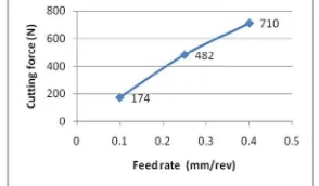
As can be seen in the Fig.11, the feed rate has the most significant effect on cutting, this is agreeable with [9]. They also said the relationship between the cutting force and feed for turning can be expressed as linier line in graph. Cutting force increases with the increase in feed due to an increase in chip load. Increase of the feed causes increase of the contact areas of chip formation, Generated temperature of chip also will increase due to more friction occur while the contact area are bigger (Fig.14).
Effect of Depth of Cut
From Fig.15 to 18 can be seen the result of cutting force, effective stress, effective strains and chip temperature at various depth of cut (DOC). The depth of cuts were varied at 0.3, 0.6 and 0.9 mm.
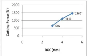
As can be seen on from Fig. 15 and Fig. 18, the increase of depth of cut cause the increase of the cutting force from 646 N to 1460 N, affective stress from 1410 MPa to 2260 MPa, affective strain from 7.8 mm/mm to 10.9 mm/mm, and generated temperature on workpiece from 1060 oC to 1220 oC.
Based Fig. 15, the increase of depth of cut cause the increase of the cutting force, this is agreeable with [9] where cutting force and feed force also increased linearly while the depth of cut were increased. This is also agreeable with theory where increase of the depth of cut cause bigger of chip thickness that also will cause increase of cutting load. This is also agreeable with [11] that the feed rate and depth of cut will greatly Figure 11. The graph of feed rate vs cutting Force
Figure 12. The graph of feed rate vs aff. stress
Figure 13. The graph of feed rate vs aff. strain
6
influence the generated cutting force which contributed about 98% to the generated cutting force.
Stress and Generated Temperature on Workpiece
Figure 19 and 20 show the effective stress and generated temperature in workpiece with cutting speed 180 m/min, feed of 0.25 mm/rev and DOC of 0.6 mm. Figure 19 shows that the biggest deformation was occurred on the primary deformation zone, followed by the secondary deformation zone. This also caused higher stress occurred in this section which reached 2600 MPa (contour line I). This result is agreeable with [13] where the major deformation during cutting process were concentrated in two region close to the cutting tool edge, and the bigger deformation were occurred in the primary deformation zone, followed by secondary deformation zone.
Generated temperature on workpiece can be analyzed in detail based on the contour in Fig. 20. The higher temperature are for the contour line I that reach 1100oC, followed by H (967 oC), G (833 oC) and so on. Figure 15 shows the contour of stress on workpiece and chip formation. This highest temperature in the chip usually occurs in this sliding region. The highest temperature in the chip usually occurs in this sliding region, while the heat generated in the sticking region caused the workpiece material to adhere with the tool. Later it was sheared which resulted in high frictional force, consequently high is generated [13].
V. CONCLUSION
The distribution of cutting force, effective stress and generated temperature obtained from simulations are agreeable with the result given by some of recently researcher and literature. From the simulation, it can be concluded that increasing cutting speed in the turning of ductile cast iron using tungsten carbide (CW) will decreasing the cutting force, stress, and strain, but increased generated temperature. High value of feed rate resulted in bigger cutting force, stress, strain and generated temperature. In addition, bigger cutting force and high generated temperature occurred at high depth of cut. The best performance usually in low cutting force, stress, strain and temperature and these were obtained on higher cutting speed, lower feed rate and depth of cut. For work piece and chip formation, the biggest deformation was occurred on the primary deformation zone, followed by the secondary Figure 15. The graph of depth of cut vs cutting force
Figure 16. The graph of depth of cut vs aff. stress
Figure 17. The graph of depth of cut vs aff. strain
Figure 18. The graph of depth of cut vs aff. temperature
Figure. 19 Effective Stress in workpiece with cutting speed 180 m/min, feed of 0.25 and depth of cut 0.6
deformation zone. Therefore higher stress occurred in this section. The highest temperature in the chip usually occurs in this sliding region. The highest temperature in the chip usually occurs in this sliding region, while the heat generated in the sticking region caused the workpiece material to adhere with the tool. Later it was sheared which resulted in high frictional force.
ACKNOWLEDGEMENT
The authors would like to thank to Government of Malaysia and Universiti Kebangsaan Malaysia for their financial support under 03-01-01-SF1214 and UKM-GUP-BTT-07-25-025 Grants.
REFFERENCES
[1] Columbus, O.H. , “DeformTM - 3D Machining (Turning) Lab”, Scientific Forming Technologies Corporation.
[2] Marusich, T.D. & Ortiz, “Modeling and Simulation of High-Speed Machining”, To appear:International Journal Num.
Metallurgy Engineering.
[3] Cerenitti A.E, Fallbohmer B.P, W. Wu C.W.T & Altan B.T, “Appl. of 2D FEM to Chip Formation in Orthogonal Cutting”,
Journal of materials Processing TechnologyVolume 59:
169-180.
[4] Cerenitti.A.E., Lazzaroni.C, Menegardo. L. & Altan. T., “Turning Simulation Using a Three- Dimensional FEM Code”,
Journal of materials Processing Technology volume 98:
99-103.
[5] Xie. J. Q, Bayoumi. A.E., & Zbib. H. M., “FEA Modelling and Simulation of Shear Localized Chip Formation in Metal Cutting”, Journal of Materials Processing TechnologyVolume 38: 1067-1087.
[6] Mackerle. J., “Finite Element Analysis and Simulation of Machining: a Bibliography (1976 – 1996)”, Journal of
Materials Processing Technology Volume 86: 17-44.
[7] Shet, C., “Finite Element Analysis of the Orthogonal Metal Cutting Process”, Journal of Materials Processing Technology
Volume 105: 95-109.
[8] Jawahir. I. S., An Intermediatary Level Short Course on Machining Process Modelling and Optimization for Improved
Productivity, Machining Research Laboratory Center for
Manufacturing, Department of Mechanical Engineering
Lexington, USA.
[9] Qian. L, Hossan, M. R., “Effect on cutting force in turning hardened tool steels with cubic boron nitride insert”, Journal of
Materials Processing Technology Volume 191: 274-278.
[10] El-Hofy, H, “Fundamentals of Machining Processes: Conventional and Nonconventional Processes”,Published by CRC Press,
http://books.google.com.my/books?id=ZdQEZ5pyCv4C&vq=c utting+
speed&dq=affecting,+temperature,+cutting+speed&source=gb s_summary_s&cad=0. Date of download : November, 10th 2008.
[11] Jaharah A.G., Abdul Rahman A., Azmi, M.N, and Che Hassan C.H, “Machinabilty of FCD 500 ductile cast iron using coated carbide Tool in Dry Machining Condition”, Proceeding National Tribology Conference, Rimba Ilmu, University of Malaya, 4-5 May 2009.
[12] Oxley, P. L. B., Mechanics of Machining: An Analytical
Approach to Assessing Machinability, 223–227 (Ellis
Horwood, Chichester, West Sussex).