A WYSIWYG Approach for
Configuring Model Layout using Model Transformations
Yu Sun
Department of Computer and Information Sciences
University of Alabama at Birmingham Birmingham, AL
Jeff Gray
Department of Computer Science University of Alabama
Tuscaloosa, AL [email protected]
Philip Langer
Department of Telecooperation Johannes Kepler University Linz
Austria
Manuel Wimmer
Business Informatics Group Vienna University of TechnologyAustria
Jules White
Department of Electrical and Computer Engineering Virginia Tech
Blacksburg, VA [email protected]
ABSTRACT
Model transformation is a core technology in Domain-Specific Modeling (DSM). While a number of model transformation languages and tools have been developed to support model transformation activities, the layout of visual models in the transformation process is not often considered. In many cases, after a transformation is performed the layout of the resulting model must be manually rearranged, which can be time consuming. The automatic layout arrangement features provided by some modeling tools usually do not take a user’s preferences or the semantics of the model into consideration, and therefore could potentially alter the desired layout in an undesired manner. This paper describes a new approach to enable users to specify the model layout in a model transformation. We applied the Model Transformation By Demonstration (MTBD) approach and extended it to let users specify the layout information using
the concept of “What You See Is What You Get” (WYSIWYG), so that the complex layout specification can be simplified.
Categories and Subject Descriptors
D.2.2-2.6 [Software Engineering]: Design Tools and Techniques; Programming Environments; I.6.5 [Simulation and
Modeling]: Model Development
General Terms
Algorithms, Design, Languages.
Keywords
Model transformation, Model Layout, Demonstration.
1.
INTRODUCTION
Model transformation is an essential part of Domain-Specific Modeling (DSM) and plays an indispensible role in many applications of model engineering (e.g., model evolution, model mapping and synchronization) [1]. A number of model transformation languages and tools have been developed providing great flexibility and power to realize various types of transformation tasks.
Although the implementation of model transformations has been well-supported, the layout of models is rarely considered. It is more straightforward to specify how the concepts and relations
in one domain should be mapped to another domain (e.g., UML models to ER models). However, preserving the original layout information in the target domain is not an easy and direct task, especially with visual models. Similarly, tools and languages are available to change and evolve models in the same domain (i.e., scaling up models, model refactoring), but how to put the newly created or modified model elements at the desired positions is often handled by manual arrangement. Ignoring the desired layout after model transformation has a strong potential to undermine the scalability of modeling approaches. Furthermore, the readability of the transformed model may be compromised, and may even unexpectedly affect the semantics under certain circumstances (e.g., when the positions of nodes correspond to special coordinates in the real world).
Several model editors (e.g., MetaCase+ [9], GMF [11], GEMS [10], and GME [12]) support automatically arranging the layout of models through fixed layout algorithms, in order to make the model more readable. However, these algorithms do not consider the original layout information and the semantics of the models, which is likely to destroy the user’s Mental Map [15]; i.e., a user’s understanding of the relationship between the entities in a diagram. Some approaches have been developed to specify a separate layout transformation [3], or a composition script that integrates the layout transformation information [2]. With these approaches, the layout configuration becomes part of the model transformation process, but the drawback is that it forces the layout to be a crosscutting concern that becomes coupled with the semantics of the model transformation. This may lead to an overwhelming amount of layout information within the transformation rule.
transformation pattern is inferred and generated by analyzing a user’s demonstrated behavior. By extending this environment, users are also enabled to demonstrate the desired layout by putting the target model elements at the correct positions, so that the generated transformation pattern can incorporate the layout information in the model transformation process.
The rest of the paper is organized as follows: a motivating example will be presented in Section 2 to better illustrate the problem and the desired results. Then, we give some background information about MTBD in Section 3. Section 4 describes how to apply and extend MTBD to ease layout configuration, followed by some discussion about the benefits and limitations of this approach in Section 5. Related works are compared in Section 6, and Section 7 offers concluding remarks.
Figure 1. Function model instances
2.
MOTIVATING EXAMPLE
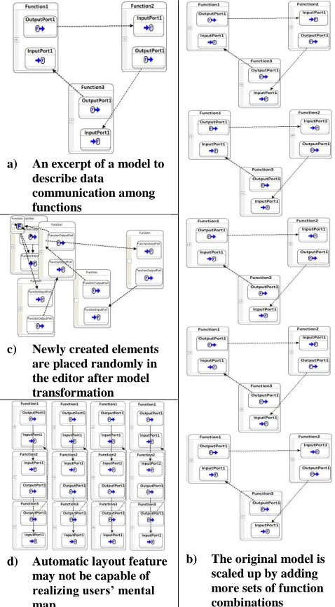
To emphasize the motivation for our approach, we present an endogenous model transformation (i.e., model transformation within the same domain) that illustrates the idea of model scalability and associated challenges with model layout. Figure 1a shows an excerpt of a domain-specific model used to specify the data communication among functions in embedded systems. Functions contain Input / Output Ports, and SignalFlow connects an Input Port with an Output Port. With the growing data communication demands, more functions are required to handle the increasing data transmission and receive requests, such that the model needs to be scaled up by adding more sets of function combinations, as shown in Figure 1b.
Because this is a typical endogenous model transformation scenario, most model transformation languages (e.g., ATL [13], C-SAW [14]) could be used to implement the process by specifying the rules about how to add new Functions, Ports, and SignalFlows, and how many of them are needed. By executing the rules, a transformation can be carried out automatically to scale the selected models. However, although the transformed model contains the semantically correct elements (i.e., the required number of newly added sets of function combinations), the newly created elements might be placed in a random location in the model editor (e.g., all of the elements that are added to a model are placed and overlapped in the upper-left corner in GEMS), so that they could be very difficult to understand without manual rearrangement (as shown in Figure 1c). Manually arranging the additional model elements is usually tedious, time-consuming and error-prone, especially when a large number of elements are involved.
Tools like GEMS and GMF provide auto-layout arrangement features as shown in Figure 1d, but the relocation resulting from the auto-layout algorithm does not consider semantic issues of the domain (e.g., the length of SignalFlow may indicate the amount of cable to be used, and the model in Figure 1d is not as illustrative as Figure 1b), nor a user’s mental map (e.g., users might prefer to have the functions connected in a triangle as in Figure 1b, but all the function combinations are listed vertically in the same y-axis as shown in Figure 1d). It is possible to specify layout information in the model transformation rules (i.e., the <x, y> coordinates of model elements is often an inherent property that can be modified with model transformation languages), but this forces the semantic intent of the model transformation rules to be entangled with layout concerns. Furthermore, even if the layout issue is specified as part of the transformation, the large amount of calculation in the design of a transformation may be overwhelming (e.g., consider the calculation of layout coordinates for 200 different types of new nodes and connections to be added in the model). Additionally, in many cases, when general model users (e.g., domain experts who are not familiar with model transformation languages) encounter the same layout problems, it would be too challenging for them to learn the languages and specify the layout information in transformation rules. Therefore, a new approach is needed to solve the layout problem with the desired features being: 1) capable of considering user preferences, 2) having the layout concern separated from the original model transformation when needed, 3) easy to arrange and specify the layout information, 4) simple to learn and use even by general users who have no programming experience.
a) An excerpt of a model to describe data
communication among functions
b) The original model is scaled up by adding more sets of function combinations c) Newly created elements
are placed randomly in the editor after model transformation
3.
OVERVIEW OF MTBD
Model Transformation By Demonstration (MTBD) [4][5] is a new approach to implement model transformations, with the goal being to enable general users like domain experts or non-programmers to realize the transformation tasks without knowing model transformation languages or metamodel definitions. While it simplifies the implementation of model transformations, it also offers a potential to improve the layout transformation as well. In this section, we first give an introduction to MTBD by explaining how to use MTBD to realize the model scalability transformation example presented in Section 2. We also show how to extend this approach to support layout specification in the next section.
Figure 2 provides an overview of MTBD. The core idea is that instead of manually using transformation languages to specify transformation rules, users are asked to demonstrate how the model transformation should be done by directly editing the source model to simulate the transformation process step-by-step. During the demonstration process, a recording and inference engine captures all the user operations (e.g., add an element, update a property, remove a connection, etc.) and infers
the user’s intention in a model transformation task, generating a
transformation pattern that summarizes the precondition of a transformation (i.e., where a transformation should be done) and the actions needed in a transformation (i.e., how a transformation should be done). This generated pattern can be executed by the engine in any model instance to carry out the same transformation process.
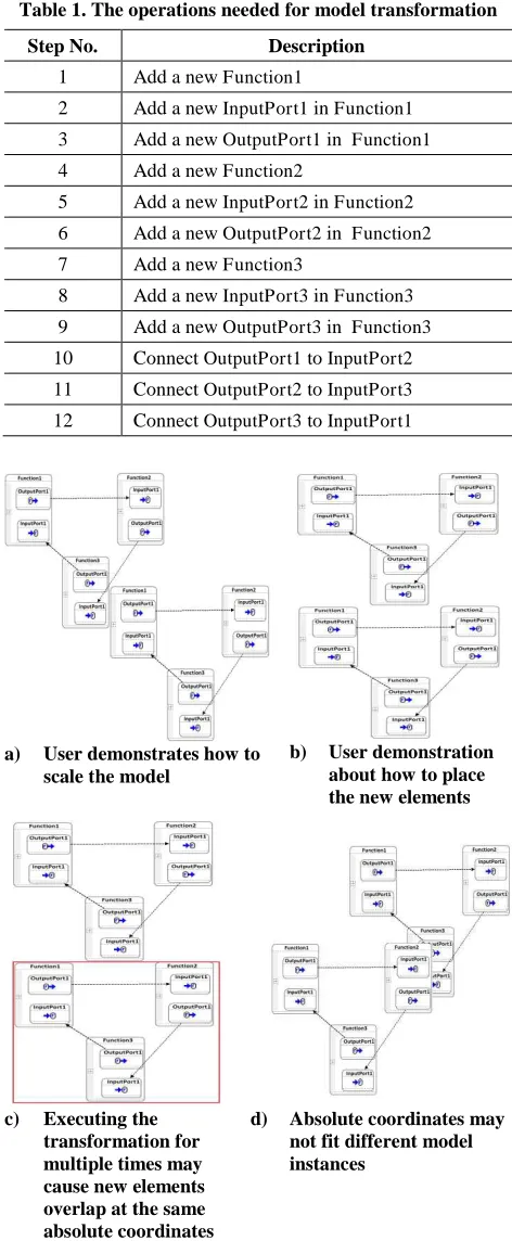
To use MTBD to scale a functional model, a demonstration could be made containing the following operations as listed in Table 1. These operations add another set of function combinations in the model editor, changing the model instance from Figure 1a to Figure 3a. All the operations are recorded by the engine in the process of demonstration. Once it is done, the engine analyzes the information recorded, and infers a generic transformation pattern that could execute the same task in any other model instance when the precondition can be satisfied. Users can also provide more specific constraints on the precondition (e.g., adding the function combination only when each existing function has exactly one input and one output port). However, we skip this step in our example to simplify the explanation and focus on the layout issue.
Figure 2. Overview of MTBD
Table 1. The operations needed for model transformation
Step No. Description
1 Add a new Function1
2 Add a new InputPort1 in Function1
3 Add a new OutputPort1 in Function1
4 Add a new Function2
5 Add a new InputPort2 in Function2
6 Add a new OutputPort2 in Function2
7 Add a new Function3
8 Add a new InputPort3 in Function3
9 Add a new OutputPort3 in Function3
10 Connect OutputPort1 to InputPort2
11 Connect OutputPort2 to InputPort3
12 Connect OutputPort3 to InputPort1
a) User demonstrates how to scale the model
b) User demonstration about how to place the new elements
c) Executing the transformation for multiple times may cause new elements overlap at the same absolute coordinates
d) Absolute coordinates may not fit different model instances
Figure 3. Model instances in demonstration and execution
back-tracking algorithm. If the precondition is satisfied, the transformation actions are carried out to transform the model. The number of execution times can also be controlled. For example, we can execute the generated transformation pattern 4 times to obtain the scaled model as shown in Figure 1c. The execution engine accesses and creates the model elements by applying corresponding APIs provided by the modeling editor. Without manual arrangement, the newly created Functions are placed in the upper-left corner of the editor randomly.
4.
EXTENDING MTBD TO LAYOUT
MTBD enables users to demonstrate the model transformation on a concrete example in the editor. We further extended it to allow users to demonstrate how to place each element in the editor, so that the layout information could be summarized and integrated in the generated transformation pattern. In most modeling tools, the location of a model element is stored in a coordinates property. Whenever model elements are placed or moved in the editor, this property will be changed correspondingly. Therefore, we modified and improved the recording engine in MTBD to be capable of recording those operations concerned with placing or moving model elements in a WYSIWYG manner, so that users can focus on demonstrating the layout without being aware of the low-level information.
4.1 Configuring Absolute Layout
As the first experiment on this approach, the most direct and simplest layout configuration is implemented using absolute coordinates. After users demonstrate their desired model transformation, the user can continue to demonstrate where to place each element in their desired location. Two new operations are added to the editor to support locating and choosing the coordinates of a certain element: 1) Set X as Current: Set X in the current coordinates as the desired X; 2) Set Y as Current: Set Y in the current coordinates as the desired Y.
Considering the motivating example, after demonstrating the 12 operations listed in Table 1, a user may begin to consider where to place each modeling element. A user may move the three new functions from the locations in Figure 3a to a new desired location, as shown in Figure 3b. Then, to confirm their decision, a user may perform the operations as listed in Table 2.
Table 2. Operations needed to set up absolute coordinates
Step No. Description
13 Set X as Current on Function1
14 Set Y as Current on Function1
15 Set X as Current on Function2
16 Set Y as Current on Function2
17 Set X as Current on Function3
18 Set Y as Current on Function3
The recording engine reads the exact values of the coordinates when these operations are performed and stores them together with the operations. The generated transformation pattern will not only contain the generic operations to transform a model at the semantic level (inferred from operations 1 – 12), but also include the operations to set up the coordinates of the elements (inferred from operations 13 – 18).
When this new transformation pattern is executed, new model elements are created and also placed at the desired location corresponding to the user’s mental map (i.e., the absolute coordinates given in the demonstration) as shown in Figure 3b.
4.2 Configuring Relative Layout
Obviously, using the two Set X / Y as Current operations to specify absolute coordinates is not flexible enough in practice. When applying the generated transformation pattern for multiple times, newly created elements will be placed in the same locations. For instance, executing the transformation pattern with the absolute coordinates 4 times will lead to creating 4 sets of function combinations, but being placed and overlapped at the same location as shown in Figure 3c. In some other cases, the absolute coordinates in the demonstration might not fit other model instances in different scenarios. An example is shown in Figure 3d - applying the transformation pattern to a model instance that already has some elements in the desired location. Thus, a more flexible and generic mechanism is needed. Relative coordinates offer a promising solution.
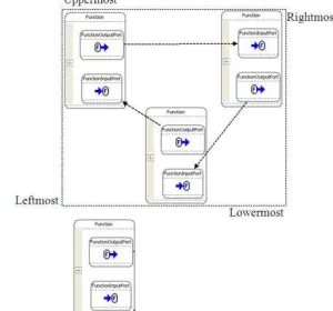
To enable users to specify relative coordinates, four more operations are introduced: 1) Set Y Relative to Uppermost: set the desired Y to be the current Y relative to the uppermost boundary of the current model instance; 2) Set Y Relative to Lowermost: set the desired Y to be the current Y relative to the lowermost boundary of the current model instance; 3) Set X Relative to Leftmost: set the desired X to be the current X relative to the leftmost boundary of the current model instance; 4) Set X Relative to Rightmost: set the desired X to be the current X relative to the rightmost boundary of the current model instance. The boundary of a model instance is specified by the minimum rectangle that includes all the current model elements as shown in Figure 4 (the single Function at the bottom is a newly added element, and the boundary is decided by the original model instance).
Figure 4. The boundary of an existing model instance
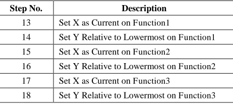
Table 3. Operations needed to set up relative coordinates
Step No. Description
13 Set X as Current on Function1
14 Set Y Relative to Lowermost on Function1
15 Set X as Current on Function2
16 Set Y Relative to Lowermost on Function2
17 Set X as Current on Function3
18 Set Y Relative to Lowermost on Function3
Similarly to processing the absolute coordinates, the recording engine calculates the distance from the current Function to the lowermost boundary of the model instance, and stores it in the generated transformation pattern.
Finally, when the transformation pattern is executed, the execution engine will read the boundary of the specific model instance and calculate the new coordinates during transformation-time. Figure 1b shows the model after executing the transformation for 4 times. In this way, the new elements created from each execution will be placed separately by the relative distance from each other, so the overlapping problem when using absolute coordinates will be prevented. Moreover, even applying the transformation pattern to a totally different model instance, the new elements can still be added at the desired relative location, rather than altering the original model in Figure 3d.
5.
DISCUSSION AND FUTURE WORK
In our initial implementation, although only simple layout operations are supported, we observed several advantages to aid model users in configuring the layout needed in model transformations. According to the criteria proposed in Section 2, the extended MTBD satisfies these very well.
Foremost, the layout is specified by users rather than applying fixed automatic layout algorithms, so that it can truly reflect a user’s desire and preserve a user’s mental map. Furthermore, the separation of the layout concern from semantic model transformations can be realized by first demonstrating the model transformation process at the semantic level and then focusing on arranging the location of the models and configuring the desired coordinates. In addition, the configuration of the coordinates is simplified through the WYSIWYG approach. Users can set up the layout by dragging and moving model elements without having to do any calculation on the X or Y coordinates. Finally, because the approach is based on MTBD, it extends the advantages of MTBD to enable general model users (including domain experts and non-programmers) to specify the layout they need without using any model transformation languages or knowing metamodel definitions.
However, some limitations also exist in the current implementation which we plan to address in the future. For instance, the relative coordinate configuration currently can only be based on the outside of the model instance boundary, rather than inside. Also, it is not yet possible to choose a certain model element as the relative center, or set up the new coordinates according to multiple relative elements.
In future work, we will tackle these limitations by introducing further layout operations allowing new elements to be positioned
relatively to existing elements, as well as to be placed inside container elements (e.g., internal states within a function block). Furthermore, we also plan to provide operations to configure layout properties other than coordinates (e.g., font styles, background colors, and styles for edges).
It might also be beneficial to enable prioritized and conditional layout operations. This, for instance, facilitates the placement of a new element on the right side of an existing element, only if there is enough space; otherwise, the new element should be placed below the existing element. To enable such operations, we will first have to provide means to query the layout of existing diagrams.
We will also explore recurrently used layout patterns such as vertical or horizontal trees and stacks. Having identified such patterns, we aim to derive configurable layout operations from these patterns enabling, for instance, to automatically position UML classes in a class hierarchy below their super classes. With this, we might be able to leverage the benefits of both approaches, configurable layout operations and automatic diagram layout algorithms.
Finally, we plan to also implement the configuration of model layout also for exogenous model transformations so that the layout of a target model is set up based on the source model’s layout.
6.
RELATED WORK
Handling and preserving model layout in model transformations according to a user’s mental map was first introduced by Pilgrim [3], who proposed to use a separate model transformation to transform the notation model that contains the layout information. Several algorithms were used to scale and adjust the layout afterwards. However, the transformation is explicitly specified and implemented by users, rather than being automatically integrated and generated, as in our approach.
Johannes and Gaul performed similar work on layout composition for domain-specific models [2], which also focuses on endogenous model transformation. In their approach, the layout composition information is delivered through a model composition script, which specifies how the source models should be composed. They also applied some algorithms to adjust the final layout to remove overlaps. Compared with our approach, the relative layout is not supported in the composition script, which is not generic enough to support the addition of layout properties.
Automatic model layout arrangement is already provided by a number of modeling tools such as MetaCase+ [9], GME [12], GMF [11], and GEMS [10]. They usually arrange the layout based on fixed algorithms. For example, such algorithms may always place children elements directly under their parent elements. However, as mentioned in Section 1, such fixed approaches do not take into consideration the domain concept or a user’s mental map.
7.
CONCLUSION
In this paper, we presented an innovative approach to configure the layout of models in a model transformation process. By using MTBD, users are enabled to demonstrate the layout information in the model editor by dragging and moving elements, while the engine will record the detailed information and generate the transformation pattern. Our initial implementation and experiments show a great improvement over the current practice in terms of the simplicity and effort in specifying the layout in model transformations. The current limitations were identified as well, which will be our future work.
8.
ACKNOWLEDGEMENT
This work is supported by NSF CAREER award CCF-0643725.
9.
REFERENCES
[1] Czarnecki, K., Helsen, S.: Feature-based survey of model transformation approaches. IBM Systems Journal 45(3), 2006, pp. 621–645.
[2] Johannes, J., Gaul, K.: Towards a generic layout composition framework for domain specific models. In Proceedings of the 9th OOPSLA Workshop on Domain-Specific Modeling, Orlando, FL, October 2009, 6 pages. [3] Pilgrim, J.: Mental map and model driven development. In
Proceedings of the 1st Workshop on the Layout of Software Engineering Diagrams. Coeur d'Alene, Idaho, September 2007, 16 pages.
[4] Sun, Y., White, J., Gray, J.: Model transformation by demonstration. In Proceedings of International Conference on Model Driven Engineering Languages and Systems, Denver, CO, October 2009, pp. 712-726.
[5] Langer, P., Wimmer, M., Kappel, G.: Model-to-Model Transformations By Demonstration. In Proceedings of International Conference on Model Transformation, Malaga, Spain, June 2010, pp. 153-167.
[6] Balogh, Z., Varró, D.: Model transformation by example using inductive logic programming. Software and Systems Modeling, 8(3), 2009, pp. 347-364.
[7] Strommer, M., Wimmer, M.: A framework for model transformation by-example: Concepts and tool support. In Proceedings of the 46th International Conference on Technology of Object-Oriented Languages and Systems, Zurich, Switzerland, July 2008, pp. 372–391.
[8] Brosch, P., Langer, P., Seidl, M., Wieland, K., Wimmer, M., Kappel, G., Retschitzegger, W., Schwinger, W.: An Example is Worth a Thousand Words: Composite Operation Modeling By-Example. In Proceedings of International Conference on Model Driven Engineering Languages and Systems, Denver, CO, October 2009, pp. 271-285.
[9] MetaCase+. http://www.metacase.com/, 2010
[10]Generic Eclipse Modeling System (GEMS). http://www.eclipse.org/gmt/gems/, 2010.
[11]Graphical Modeling Framework (GMF), http://www.eclipse.org/modeling/gmf/, 2010.
[12]Lédeczi, A., Bakay, A., Maróti, M., Völgyesi, P., Nordstrom, G., Sprinkle, J., Karsai, G.: Composing domain-specific design environments. IEEE Computer, vol. 34, no. 11, 2001, pp. 44-51.
[13]Jouault, F., Allilaire, F., Bézivin, J., Kurtev, I.: ATL: A model transformation tool. Science of Computer Programming, vol. 72, nos. 1/2, 2008, pp. 31-39.
[14]Gray, J., Lin, Y., Zhang, J.: Automating change evolution in model-driven engineering. IEEE Computer, Special Issue on Model-Driven Engineering, vol. 39, no. 2, 2006, pp. 51-58.