On the Reduction of Interference Effect Using Power
Control for Device-to-Device Communication
Underlying Cellular Communication Network
Misfa Susanto, Helmy Fitriawan,
Andri Abadi, HerlinawatiElectrical Engineering Department, University of Lampung, Jl Prof. Sumantri Brojonegoro No 1, Bandar Lampung 35145, Indonesia
Abstrac—Device-to-Device (D2D) communication has currently been emerging as a promising technology to increase capacity and to extend coverage area in cellular communication network. D2D communication allows direct communication between two or more devices such as mobile user equipments without any base station help as a relay. However, enabling D2D features in cellular communication network will reveal more complex interference problems, because D2D communication could share the same frequency resources as its underlain cellular communication network. This paper analyzes the interference problems in such D2D communications underlying cellular communication network for downlink transmission. This paper explores the use of power control methods to reduce the effect of interference. The decision whether to increase or to decrease the power level on base station (evolved Node B/eNB in Fourth Generation/4G Cellular Networks) or on the transmitter of D2D pair (Transmitter of D2D User Equipment/TUE) is based on the estimated current Signal to Interference plus Noise Ratio (SINR). First method of power control (PC-1) uses a fixed value to control the power level of the transmitter. Another one (PC-2) uses moving average of interference power values. The simulation was carried out to evaluate those two power control methods and its results in term of Cumulative Distribution Function (CDF) of SINR are compared to the system without power control method. The simulation results show that both power control methods contribute the improvement of performances; for one cellular equipment (CUE) and 100 pairs of D2D it achieved the improvement of SINR distribution at 5% with PC-1 and at 4% with PC-2 compared to the system without powr control, meanwhile for 1 D2D pair and 100 CUEs the CDF of SINR at 0 dB achieves 40%, 3%, and 0% for the systems without power control, with PC-1, and PC-2 methods, accordingly.
Keywords—D2D Communication; Cellular Communication Network; Downlink Cellular Network; Interference Problem; Power Control; Constant Step Power Control; Moving Average Based Power Control.
I. INTRODUCTION
Device-to-Device (D2D) communication is a promising solution to increase capacity and to extend the coverage area when it is applied in cellular communication network. D2D has been considered as one of emerging technologies for 5G wireless communication networks. However, enabling D2D communications in cellular networks will face more complex interference problems, because D2D communication could
shares the same frequency resources as its underlain cellular network. Therefore, the interference management to reduce its effects is important to be addressed.
One obvious solution to the interference problems caused by enabling D2D communications in cellular communication network is separating the frequency spectrums allocated for D2D communications and cellular communications as in [1-3]. However, one can argue that this solution can somehow less effective, because in the area that D2D is less used the frequency spectrum allocated for D2D communication will be wasted. There are other solutions to reduce the interference effects for D2D communication underlying cellular communication network. One of the solutions is using the power control method.
In this paper D2D and cellular communication are sharing the same frequency resources and then this paper proposes the use of power control methods to reduce the interference effects in D2D communications deployed in cellular communication network. Two power control methods are considered in this paper. One power control called as PC-1 has been applied for the interference management in femtocell-macrocell cellular networks in [4-5]. Another power control method called as PC-2 is our new proposal discussed in this paper.
Following this introduction, this paper is organised as the following. Section 2 describes the system model considered in this paper. Section 3 presents the simulation setting and parameters and discusses the simulation results. Section 4 concludes the paper and discusses likely further outlook of this work.
II. SYSTEM DESCRIPTION AND MODELS
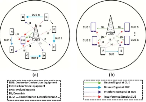
frequency resources used for the cellular communication network. In this first scenario, this paper investigates the effect of interferences caused a number of D2D communications on one CUE1 being served by eNB in the cellular network and the SINR distribution on RUE will be analyzed. This first scenario is shown on Fig. 1 (a). The second scenario analyze the interference effects on the receiver of D2D communication (RUE) caused by eNB. On the single cell of cellular network, it is deployed a number of CUEs and one pair of D2D communication. In this second scenario it is observed the interference effect on RUE caused by eNB and the SINR distribution on the CUEs is also analyzed through simulation. For the first scenario, let Ptx_eNB indicate the transmit power on the transmitter (eNB). Thus, the received power, Prx_MUE1_eNB, at the receiver side (at the CUE1 that desires to receive the signal) can be calculated as below [6].
_ _ = _ . _ (1)
where
Ptx_eNB : Transmit power of eNB (in the power unit);
GeNB_CUE1 : the channel gain from eNB to CUE1.
GeNB_CUE1 can be calculated by the following equation.
GeNB_CUE1 = PLeNB_CUE1.heNB_CUE1 (2)
where PLeNB_CUE1 denotes the path loss between eNB to CUE1 dan heNB_CUE1 is the small scale fading factor for the channel from eNB to CUE1. This paper does not take the small scale fading effect into account, so GeNB_CUE1 characterizes the path loss caused by just the distance. In this case, Ptx_eNB .GeNB_CUE1 denotes the received power at the distance d. By not considering the small scale fading effects,
GeNB_CUE1 can be denoted as a propagation model. Many
propagation models have been proposed in the literatures. The one that is adopted in this paper is the propagation model presented in [7]. That propagation model in decibel (dB) unit is stated as follow.
For the cellular links (between user equipments (D2D User Equipment/DUE and CUE) to eNB or vice versa):
( ) = 128.1 + 37.6 ( ( )) (3) For D2D links that is the link between Transmitter of D2D User Equipment (TUE) to Receiver of D2D User Equipment (RUE):
= 148 + 40 ( ( )) (4)
where
PLcellular links : path loss from User Equipments (DUE or
CUE) to eNB or vice versa;
PLD2D links : path loss for the D2D communication pairs
from TUE to RUE;
d : the distance between the transmitter and receiver in km.
On the observed CUE1, the Signal to Interference Noise plus Noise Ratio (SINR) at CUE1 can be calculated as below.
, = ( ) ,_ ._ , (5) resources, 0 and 1 are for the different and same resource used, resperctively;
, : the channel gain between TUE that
interferes and CUE1; N : the power of system noise.
_ _ can be calculated using Eq. 1 and the interference
power caused by TUEk that uses the same resource as the cellular system can be found using Eq. 1 by replacing the indices eNB with TUEk as the transmitter and the indices for CUE1 remains the same as the receiver that is the terminal being observed. As it is mentioned early that this paper does not consider the small scale fading factor and the same assumption applies for the link from TUEk to CUE1.
2.1 Proposed Power Control Method
This paper applies power control methods to reduce the interference effects on the downlink transmission in D2D communication underlying the cellular communication networks. The power control method is applied on both sides; on sides of the D2D and cellular communications. Suppose we consider the interference effects on the cellular communication first. For the case of observing D2D communication, the all equations in the following descriptions are applied by replacing the indices accordingly. In order to reduce the effect of interferences, it can be performed by adjusting the transmit power of the desired transmitter, i.e. eNB in this case. The transmit power of eNB, Ptx_eNB is contained in the numerator of Eq. 5. The transmit power of desired transmitter at the current time of frame transmission,
Ptx_eNB(ti), will be adjusted that is increased or decreased or
kept the same at the next time of frame transmission producing a new value of the transmit power, Ptx_eNB(ti+1). This paper introduces γ as a parameter of power control to increase or to decrease the transmit power. The γ will increase or decrease the transmit power at the next time of frame transmission based on the estimated value of current time of SINR (SINRest(ti)). SINRest(ti) will be compared to the pre-determined SINRtarget. Based on this argument, this paper introduce an indicator parameter, k, to indicate whether the value of γ will increase the transmit power or decrease the transmit power or keep the same of transmit power for the next time of frame transmission. The general expression of Ptx_eNB(ti+1) can be written as below.
Ptx_eNB(ti+1) = Ptx_eNB(ti) + k.γ (6)
The value of k will be determined according to the value of SINR(ti). In this case, there are three likely conditions of
SINRest(ti). Those conditions are: (1) if SINRest is same as
SINRtarget, then k will be equal to 0; (2) if SINRest is smaller
control methods namely Power Control 1 (PC-1) and Power Control 2 (PC-2). How the values of k and γ influence the two power controls are explained later on in this section.
Another condition has to be met by the power control method is that the value of _ ( ) in Eq. 6 must not exceed the value of maximum and not be lower than the minimum transmit powers of eNB, Pmax and Pmin, respectively. Then, the final value of _ ( ) at the next time of frame transmission as the output of power control method will determined based on the below expression. To avoid the confusion, _ ( ) that is calculated in Eq. 6 is re-denoted as _ ( ) in the below expression.
_ ( ) =
_ ( ), ; if ( )
_ ( ); if ( ) =
_ ( ), ; if ( )
(7)
The functions of max{a,b} and min{a,b} are the functions that return the maximum and minimum values, respectively, among the given set in the function arguments, it is a and b. Eq. (7) will guarantee that the power output of power control methods within the limits of allowed transmit powers of user equipments (CUE and TUE) and eNB.
2.1.1 Power Control Method 1 (PC-1)
This paper mean Power Control Method 1 (PC-1) as controlling the transmit power with a fix value to increase or
to decrease the transmit power. The way of this power control method is simple and practically can be implemented easily. As in [4] and [5], we have applied this power control method for two-tier femtocell-macrocell cellular network. PC-1 uses a fixed value of the multiplication of k and γ. The value of γ is set to be a constant which is to be a simulation parameter. Whereas, the values of k according the values of SINRest(ti) which is explained early can be expressed as below.
=
+1; if ( ) 0; if ( ) =
1; if ( )
(8)
2.1.2 Power Control Method 2 (PC-2)
This paper uses the different values of multiplication between k and γ to increase or to decrease the transmit power in power control method 2 (PC-2). It is depicted in the expression below.
=
+2; if ( ) 0; if ( ) =
1; if ( )
(9)
The different values of k when SINRest(ti) is less than
SINRtarget and SINRest(ti) is greater than SINRtarget are purposed
to take the different effects to the controlled transmit power when it is increased or decreased.
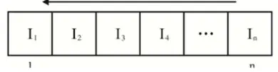
The value of γ in PC-2 is based on the average received interference powers at the observed terminal (UE1). The calculation of average interference powers is based on the moving average method as illustrated in Fig. 2. The shift register is used to store the interference powers detected at the observed terminal (UE1). Then the average value of interference powers is calculated using Eq. 10.
̅ = ∑ (10) Then, the value of γ is calculated using the expression below.
= ( ) ̅ (11)
The SINR distributions at the Cellular User Equipment and Receiver of D2D User Equipments are analyzed through simulation.
III. SIMULATION SETTING,RESULTS, AND DISCUSSIONS Extensive simulation experiment has been carried out. This paper considers the network scenorios as shown in Fig. 1 and was discussed in the previous section. A single cell cellular network is considered with the position of eNB at the center of cell and the maximum and minimum transmit powers of eNB are set to be 46 dBm and 10 dBm, respectively [8]. The transmit power of eNB without power control as well as the initial value of eNB’s transmit powe is set to be 34 dBm. The cell radius of cellular network is set to be 2000 meters which is according to the cell in the rural area. Both CUE and DUE pairs are randomly deployed in the coverage area of cell of cellular network. The transmittiong range of TUE of D2D pairs is set to 1000 meters [9]. The RUEs of D2D pairs are guaranteed to be deployed within the transmitting range of its corresponding TUEs. The maximum and minimum of tranmit powers of user equipments (CUE and TUE) are 23dBm and -40 dBm, respectively [9]. The transmit power of TUE for the system without power control is set to 17 dBm as well as for the initial transmit power of TUEs when power control methods are not applied. The system bandwidth is set to 20 MHz [8] and the system noise is set to -174 dBm/Hz [10]. The value of γ for PC-1 is set to be 2 dB and we set the SINRtarget to 0 dB which is according to the SINR value for the voice and audio traffics [11]. Note that all simulation experiments were repeated for 100 times of simulation experiments and the collected simulation results were averaged. Table 1 summaries the values of simulation parameter mentioned above.
To determine the number of D2D pairs, we were carried out the scenario on Fig. 1 first with one CUE and D2D pairs are increased. And then, we plot the SINR results with respect to the number of D2D pairs and it is shown on Fig. 3. It is noticed in Fig. 3 that as the number of D2D pairs id increased, the SINR at CUE1 is decreased and it achieves below the
SINR target of 0 dB for 100 D2D pairs without power control method. Fig. 3 plots the SINR results at CUE1 with PC-1 and PC-2 methods as well. It is noticed that PC-1 and PC-2 methods improve SINR performances in Fig. 3 by 9.75 dB and 11 dB, respectively. It because as PC-1 and PC-2 methods work by adjusting the transmit power according to the estimated SINR and interference values. Based on this result of Fig. 3, we found that 100 D2D pairs are enough to evaluate further the system performances in terms of the SINR distribution.
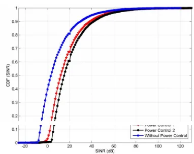
The second simulation experiment was carried out for the scenario in Fig. 1 (a) with 1 CUE and 100 D2D pairs. The Cumulative Distribution Function (CDF) of SINR for RUE of D2D pairs and it is plotted in Fig. 4 and also the SINR at CUE1 was measured. The SINR at CUE1 was found at 1.7087 dB, 12.4687 dB, and 13.5887 dB for without power control, with PC-1, and with PC-2, accordingly. It can be noticed in Fig. 4 that at SINR of 0 dB the CDF of SINR at RUEs achieves 87%, 82%, and 83% for the systems without power control, with PC-1, and with PC-2 methods, respectively. It achieved the improvement of SINR distribution at 5% with PC-1 and at 4% with PC-2. The reasons for this improvement is power control effectively adjusting the transmit power when the SINR was lower than SINR target of 0 dB.
TABLE I. SIMULATION PARAMETERS
No. Parameter Value
1. Number of Cell of Cellular Network 1
2. Radius of Cell of Cellular Network 2000 meters 3. Transmit power of eNB without Power Control 34 dBm 4. Initial transmit power of eNB with Power
Control
34 dBm
5. Maximum Transmit Power of eNB 46 dBm
6. Minimum Transmit Power of eNB 10 dBm 7. TUE Transmission Range 1000 meters 8. Transmit power of TUE withour Power Control 17dBm
Initial transmit power of TUE with Power Control
17 dBm
9. Maximum Transmit Power of TUE 23 dBm 10. Minimum Transmit Power of TUE -40 dBm
11. γfor PC-1 2 dB
12. Noise Power Density -174 dBm/Hz
13. System Bandwidth 20 MHz
14. Simulation Time (Number of Iterations) 100
Third simulation experiment was performed for the scenario in Fig. 1 (b) with 1 D2D pair and 100 CUEs. In this third simulation scenario, the CDF of SINR for CUEs was measured and it was plotted in Fig. 5. Also, in this third simulation experiment the SINR on RUE of D2D pair was determined. The SINR value at RUE in this scenario was found at -16.4954 dB, -11.0754 dB, and -14.4052 dB for the systems of without power control, with PC-1, and with PC-2, respectively. The CDF of SINR in Fig. 5 shows that the CDF of SINR at 0 dB achieves 40%, 3%, and 0% for the systems without power control, with PC-1, and PC-2 methods, accordingly. It can be noticed that PC-1 and PC-2 methods significantly improve the SINR performances. Power control methods worked well to reduce the interference effects at RUE, because the transmit power of eNB was solely interference factor for the considered scenarios.
IV. CONCLUDING REMARKS
This paper has analyzed the fundamental scenario for the interference problems in D2D communication underlying cellular communication network. The interference effects were considered at both sides of D2D communication and cellular communication. On the purpose to reduce the interference effects, this paper uses power control methods. Two power control methods, namely PC-1 and PC-2, have been studied on the downlink transmission for the single cell of cellular network. The extensive simulation has been carried out for single cell of cellular network having a number of D2D pairs deployed. The SINR distributions have been learnt at both sides of cellular user equipments and D2D receiver user equipments. The simulation results show that both power control methods work well to reduce the interference effects at CUEs and RUEs. It was depicted that large gain of power control has been achieved to reduce the interference effects at RUEs. For one cellular equipment (CUE) and 100 pairs of D2D it achieved the improvement of SINR distribution at 5% with PC-1 and at 4% with PC-2 compared to the system without power control, meanwhile for 1 D2D pair and 100 CUEs the CDF of SINR at 0 dB achieves 40%, 3%, and 0% for the systems without power control, with PC-1, and PC-2 methods, accordingly. The simulation results can be extended to collect the Bit Error Rate (BER) performance as well as the throughput performance. It is planned as the near future plan for this paper.
ACKNOWLEDGMENT
Authors would like to thank for the anonymous reviewers for reviewing this paper to have better presentations.
REFERENCES
[1] Y. Zhang, C. Y. Wang, and H. Y. Wei, “Incentive compatible mode selection and spectrum partitioning in overlay D2D-enabled network”, in the proceeding of 2015 IEEE Globecom Workshops (GC Wkshps), pp. 1-6, December 2015.
[2] F. Jiang, X. C. Wang, C. B. Li, and B. Y. Shen, “Dynamic power control based on FFR for D2D communication underlaying cellular networks”, in the proceeding of 2016 8th International Conference on Wireless Communications & Signal Processing (WCSP), pp. 1-6, October 2016. [3] Z. Dai, J. Liu, and C. Wang, “QoS-based device-to-device
communication schemes in heterogeneous wireless networks”, IET Communications, Vol. 9, No. 3, pp. 335-341, February 2015.
[4] M. Susanto, R. Hutabarat, Y. Yuniati, and S. Alam, “Interference management using power control for uplink transmission in femtocell-macrocell cellular communication Network”, 15th International Conference on Quality in Research (QiR) 2017, 24 – 27 July 2017, Bali – Indonesia.
[5] M. Susanto, D. Fauzia, Melvi, S. Alam, “Downlink power control for interference management in femtocell-macrocell cellular communication network”, 15th International Conference on Quality in Research (QiR) 2017, 24 – 27 July 2017, Bali – Indonesia.
[6] B. Guo and S. Sun, “Interference Management for D2D Communications Underlying Cellular Networks at Cell Edge”, in the proceeding of ICWMC 2014: The Tenth International Conference on Wireless and Mobile Communications, pp. 118-123, IARIA, 2014. [7] S. Hakola, T. Chen, J. Lehtomaki, and T. Koskela, 2010.
“Device-to-Device (D2D) communication in cellular network – performance analysis of optimum and practical communication mode selection”, in the proceeding of 2010 IEEE Wireless Communication and Networking Conference, pp. 1-6, April 2010.
[8] 3GPP TR 36.942 version 10.2.0 Release 10, “LTE; Evolved UniversalTerrestrial Radio Access (E-UTRA); Radio Frequency (RF)
System Scenarios”, European Telecommunications Standards Institute, May 2011.
[9] S. Mumtaz, K. M. S. Huq, and J. Rodriguez, 2014. “Direct Mobile-to-Mobile communication: paradigm for 5G” IEEE Wireless Communication, Vol. 21, No. 5, pp. 13-23, October 2014.
[10] 3GPP TR 36.814 version 10.2.0 Release 10, “3rd Generation Partnership Project; Technical Specification Group Radio Access Network; Evolved Universal Terrestrial Radio Access (E-UTRA); Further Advancements for E-UTRA Physical Layer Aspects (Release 9)”, European Telecommunications Standards Institute, March 2010.
[11] U. Kolger, G. D. Galdo, A. Grosch, and M. Haardt, “Quality of Services oriented spatial processing in the Manhattan grid”, 2008 International ITG Workshop on Smart Antennas, pp. 362-369, February 2008.
Fig. 3 SINR values as the number of increased D2D pairs under single cell scenario of cellular network with one cellular user equipment without power control and with power control methods 1 and 2 (PC-1 and PC-2)
Fig. 5 CDF of SINR at RUE for Scenario Fig. 1 (b) without power control, with PC-1 (power control 1), and with PC-2 (power control 2) Fig. 4 CDF of SINR at CUE for Scenario Fig. 1 (a) without power control,