Karakteristik Aerodinamika Flying Boat pada Ketinggian Ground Effect (Studi Kasus Model Remote
Control Flying Boat Pada Ketinggian 0,2 m dan 1 m), (Sayuti Syamsuar)
139
WARTA ARDHIA
Jurnal Perhubungan Udara
Karakteristik Aerodinamika
Flying Boat
pada Ketinggian
Ground Effect
(Studi Kasus
Model
Remote Control Flying Boat
Pada Ketinggian 0,2 m dan 1 m)
The Aerodynamic Characteristics of A Flying Boat on the Ground Effect Altitude (Case
Study: A Flying Boat Remote Control Model at 0,2 m and 1 m altitute)
Sayuti Syamsuar
Pusat Teknologi Industri dan Sistem Transportasi, Badan Pengkajian dan Penerapan Teknologi Email: sayutisyamsuar@yahoo.com
INFO ARTIKEL ABSTRACT / ABSTRAK
The paper presents an analysis of the flight performance and stability and control of a Flying Boat remote control model on the ground effect altitude. It begins with a three dimensional measurement of a Flying Boat remote control model by using a laser tracking photo camera and a drawing software. The 3 D model was drawn by solid drawing on the CATIA software. The 3 D model was analyzed by using computational fluid dynamics CFx AnSys due to the rectangular wing with dihedral configuration with NACA 23012 airfoil. The maximum takeoff weight is around 25.0 kg powered with a single engine propeller, 5.5 HP. The surface effect phenomena of the Flying Boat remote control model was simulated by using CFx Computational Fluid Dynamics software, AnSys with the airspeed, V = 35.0 knots and shows a good results at the altitude of 20.0 cm. The longitudinal static stability analysis provides a good result at 1.0 meter altitude. Simulations were performed to the PUNA “Alap alap” flight performance test during cruise at 7800 feet as data verification. The adaptive ground effect control system is solved by transfer function equation matrix.
Makalah ini berisikan analisis prestasi terbang dan kestabilan dari pesawat remote control model jenis Flying Boat pada ketinggian terbang ground effect. Pada awalnya, dilakukan pemotretan 3 D terhadap pesawat model Flying Boat menggunakan kamera laser beserta piranti lunak pendukung dan kemudian menggunakan solid drawing pada program CATIA. Model 3D dianalisis dengan menggunakan piranti lunak CFx AnSys untuk keseluruhan badan dan sayap dengan airfoil jenis NACA 23012. Karakteristik dinamik dari pesawat model dengan MTOW = 25.0 kg dengan power 5.5 HP terlihat dengan baik pada ketinggian terbang 20.0 cm dengan kecepatan, V = 35.0 knots. Sedangkan, analisis kestabilan statik matra longitudinal terlihat dengan respons waktu (t) yang baik pada ketinggian terbang 1.0 meter. Simulasi terbang menampilkan uji prestasi terbang pesawat nir awak PUNA “Alap alap” saat cruise pada ketinggian 7800 feet sebagai data verifikasi. Model matematika sistem Kendali Terbang Adaptif Ground Effect dianalisis dengan matriks persamaan fungsi transfer.
Histori Artikel: Diterima: 10 Juni 2015 Direvisi: 11 Agustus 2015 Disetujui: 29 September 2015
Keywords:
Flying Boat, remote control model, ground effect altitude
Kata kunci:
140
Warta Ardhia, Volume 41 No. 3 September 2015, hal. 139-146INTRODUCTION
Nowadays, Unmanned Aerial Vehicles (UAV’s) are used widely in civil and military applications. New generations of UAV’s will be much more advanced, completely autonomous and independent from being controlled by the Pilot. On this study, the Remote Control model Flying Boat is used to determine the ground effect characteristics at the 0.20 meter altitude using CFx AnSys analysis and the longitudinal stability at the 1.0 meter altitude with the Matlab software.
The simulation of the numerical analysis has been done on the full configuration of Flying Boat remote control model during hydro planing and airborne from the water surface. The hydro planing airspeed on the water surface, V is around 25.0 knots. The aim of this study is to known the aerodynamic characteristics and the longitudinal static stability at the ground effect altitude.
The analysis of the aero- and hydrodynamics characteristics of the full configuration model are calculated by using CFx AnSys software and Matlab software. The surface effect phenomenon of the Flying Boat remote control model occurs from the wing tip vortex at 20.0 cm altitude height within airspeed of V = 35.0 knots. The purpose of the computational fluid dynamics analysis of the three dimensional model are to known the downwash effect, flow visualization and to known the thrust per weight ratio effect.
An autonomous controller has to guarantee the accuracy of the tracking part, and the robustness with respect to environmental disturbances (A. Sarhan, 2013). The system simulation technology could do the argumentation and feasibility analysis for the unfounded system, and do the basic work for system design (Chao Yun et al., 2013).This paper is a part of the author research study during Ph. D program at the Faculty of Technology, Institute Technology of Sepuluh Nopember, Surabaya.
LITERATURE REVIEW
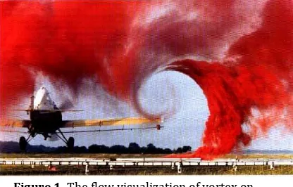
The history of Wing in Surface Effect craft The wing In Surface effect is a phenomenon that affects all aircraft in some way, due to vortices of air that become trapped between the wings of an aircraft and the ground (when the aircraft is near to the ground). It is important to note that ‘ground’ may refer to not only land, but also water, ice, snow and sand. The effects of the wing in surface effect can be beneficial or detrimental to the aircraft. Various craft have been designed on the world, specifically to utilize the benefits of this surface effect, and hence are not actually regarded as ‘aircraft’. Although development of Wing in Surface Effect craft has taken place over many decades, the technology has not progressed to the point where such craft can become a mainstream commercial success, due in part to early design inefficiencies and a lack of government funding for research and development in this area worldwide. However, it is still widely believed that the potential exists for Wing in Surface Effect craft to have practical applications. The topics or research of Surface Effect craft are founding in Taiwan, South Korea, China, Malaysia and Indonesia also. This paper investigates the applications of the Wing in Surface Effect craft C type by using Flying Boat remote control model simulation. The phenomenon of surface effect can be seen as vortices on the wing tip of aircraft are shown in Figure 1.
Figure 1. The flow visualization of vortex on wingtip.
Karakteristik Aerodinamika Flying Boat pada Ketinggian Ground Effect (Studi Kasus Model Remote
Control Flying Boat Pada Ketinggian 0,2 m dan 1 m), (Sayuti Syamsuar)
141
There are many different shaped bodieswhich can produce lift; however the most efficient design so far is wing. Wings generate lift because the movement of the wing through air results in a higher static pressure on the lower surface than on the upper surface. This difference in pressure results in an upwards force known as lift which allows the aircraft to overcome its weight force acting downwards. The flight performance about the aero and hydrodynamics characteristics of Flying Boat remote control model during hydro planing were analysis by CFD on this paper.
The Wingtip vortex
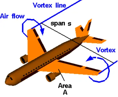
For a lifting wing, the air pressure on the top of the wing is lower than the pressure below the wing. Near the tips of the wing, the air is free to move from the region of high pressure into the region of low pressure. The resulting flow at the left by the two circular blue lines with the arrowheads showing the flow directions shown in Figure 2.
Figure 2. Wingtip vortex theories. (Source: Benson. T, 2005)
As the aircraft moves to the lower left, a pair of counter-rotating vortices is formed at the wing tips. The lines marking the center of the vortices are shown as blue vortex lines leading from the wing tips. If the atmosphere has very high humidity, you can sometimes see the vortex lines on an airliner during landing as long thin "clouds" leaving the wing
tips. The wing tip vortices produce a downwash of air behind the wing which is very strong near the wing tips and decreases toward the wing root. The effective angle of attack of the wing is decreased by the flow induced by the downwash, giving an additional, downstream-facing, component to the aerodynamics force acting over the entire wing (Benson, T. 2005). The downstream component of the force is called induced drag because it faces downstream and has been "induced" by the action of the tip vortices. The lift near the wing tips is defined to be perpendicular to the local flow (Benson, T, 2005). The local flow results in a lower effective angle of attack than the free stream flow because of the induced flow. Resolving the tip lift back to the free stream reference produces a reduction in the coefficient of the entire wing.
METHODOLOGY
The research begins with a three dimensional measurement of a Flying Boat remote control model by using a laser tracking photo camera and a drawing software. The 3 D model was drawn by solid drawing on the CATIA software. The 3 D model was analyzed by using computational fluid dynamics CFx AnSys due to the rectangular wing with dihedral configuration with NACA 23012 airfoil. The maximum takeoff weight is around 25.0 kg powered with a single engine propeller, 5.5 HP.
NACA 23012 airfoil
NACA 23012 airfoil was developed by E. Lasauskas, et al., 2007, the Reynolds number, Re and amplification ratio was varied to achieve good comparison of calculated and measured drag polar. Figure 3 shows the original NACA 23012 airfoil for the wing.
142
Warta Ardhia, Volume 41 No. 3 September 2015, hal. 139-146 Figure 4 shows the aerodynamiccharacteristics of the NACA 23012 airfoil, with trailing edge short tab and long tab.
Figure 4. The aerodynamics characteristic of NACA 23012 airfoil (original and
modification). (Source: E. Lasauskas, 2007)
The comparison of the calculated and measured data of the original NACA 23012 airfoil and an airfoil with a trailing edge tab (long tab) at Re 2.0 x 10⁶ and n = 0.1 full turbulence flow is shown in Figure 5.
Figure 5. The drag polar of NACA 23012 airfoil.
(Source: E. Lasauskas, 2007)
The verification of flight control system The system verification of Adaptive Control Ground Effect is based on the flight performance criteria as shown in Figure 6. The Thrust per Weight (T/W) ratio is around 0.4 for the three configurations. While the Aspect Ratio, ARPUNAof PUNA “Alap-alap” is
around 10.0, and the ARFLYING BOAT of RC model Flying Boat is around 5.0 and then the ARLIPPISCH of RC model NA-4 Lippisch configurations is around 3.5.
Figure 6. The verification method of Ground Effect Adaptive control
The adaptive control design
In Figure 7, yv is the output signal contaminated by noise and ye are the output signal modified by Kalman Filter. The input signal is a step signal. The w (t) is amplitudes of the interference controlling signal and v (t) is noise measurement signal. It can eliminate the static error by combination of Kalman Filter and Proportional Integrator Differentiator (PID) controller. It can ensure the system design is simple, robustness is strong and reliable. Kalman Filter is used to filter the detected signal noise and extract the true signal as a feedback. The PID controller calculates error as the difference between a measured process variable and the desired set point. PID can solve the existing problems and improve the dynamic response of the UAV.
Karakteristik Aerodinamika Flying Boat pada Ketinggian Ground Effect (Studi Kasus Model Remote
Control Flying Boat Pada Ketinggian 0,2 m dan 1 m), (Sayuti Syamsuar)
143
The mathematical model for adaptive controldesign is shown on below:
Jacklin, et al., 2008 on Figure 8.
Figure 8 The Linear Quadratic Gaussian (LQG) controller on the aircraft. (Source: Stephen A. Jacklin, et al., 2008)
DISCUSSION
The aero and hydrodynamic computational results by using CFx AnSys software are presented on Figure 9 to Figure 13.
Figure 9 shows the meshing of the Flying Boat remote control model with airspeed, V = 25.0 knots and angle of attack, α = 50 during hydro planing on the water surface.
Figure 9. Meshing of the model with angle of attack, α = 50, airspeed, V = 25.0 knots. Figure 10 shows the Pressure Distribution with airspeed, V = 25.0 knots and angle of
attack, α = 50 during hydro planing on the water surface.
Figure 10. Pressure Distribution of the model with angle of attack, α = 50, airspeed, V = 25.0
Figure 11. Air Velocity Vector of the model with angle of attack, α = 50, airspeed, V = 25.0 knots.
Figure 12 shows the Force – Z (lifting) distribution of the model with airspeed, V = 25.0 knots and angle of attack, α = 50 during hydro planing on the water surface.
Figure 12. Force – Z (lifting) Distribution of the model with angle of attack, α = 50, airspeed, V =
25.0 knots.
144
Warta Ardhia, Volume 41 No. 3 September 2015, hal. 139-146 Figure 13 Water volume fraction of the FlyingBoat model with angle of attack, α = 00, airspeed, V = 35.0 knots
The results of the longitudinal static stability parameters, such as acceleration, ax, pitch presented in the same chart in Figure 14.
Figure 14. The longitudinal static stability parameters response.
Some results of adaptive ground effect control design of Flying Boat remote control model and PUNA “Alap alap” flight performance testing are presented in Figure 15, Figure 16 and Figure 17.
The state space of longitudinal equation in the model transfer function of aircraft is presented on below:
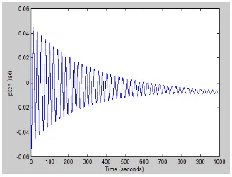
around 0.91 with transfer function on below:
Figure 15. The pitch angle, θ response on the closed loop with PID controller.
Karakteristik Aerodinamika Flying Boat pada Ketinggian Ground Effect (Studi Kasus Model Remote
Control Flying Boat Pada Ketinggian 0,2 m dan 1 m), (Sayuti Syamsuar)
145
Figure 16. The pitch angle, θ response on the closed loop with Kalman Filter.
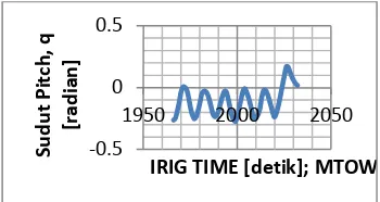
The pitch angle, θ during cruise at 7800 feet altitude of PUNA “Alap alap” flight testing is shown in Figure 17.
Figure 17. The pitch angle, θ during cruise at
7800 feet altitude of PUNA “Alap alap” flight testing.
CONCLUSIONS
The ground effect phenomena of RC model Flying Boat were successfully presented in two cases. The first case was in the fluid dynamics analysis CFx AnSys. The second case was calculated by Matlab for the longitudinal static stability and control analysis. The adaptive ground effect control design was successfully performed by tuning the PID controller analysis and Kalman Filter in Matlab with the closed loop transfer function method. The pitch angle, θ parameters from model and flight testing data are comparable. The aerodynamic characteristics of Flying Boat remote control model is satisfied due to the CFD computational.
ACKNOWLEDGEMENTS
The authors would like to thank the Head of the Agency for the Assessment and Application of Technology for the financial support to conduct the study.
The authors also express their earnest gratitude to the head and staffs of the Transportation System Technology Division, the Head and staffs of the MEPPO Laboratory, Puspiptek, Serpong, the Director of PTIM and
staffs on the Drawing and Computational Rooms, Puspiptek, Serpong, the Head and staffs of the Indonesia Hydrodynamic Laboratory, Surabaya, and, to thank the director of PTIPK-TIRBR, and staffs.
REFERENCES
Sarhan, M. Ashry, (2013), Self Tuned PID controller for the Aerosonde UAV Autopilot, International Journal of Engineering Research and Technology (IJERT) ISSN: 2278-0181, Vol. 2.
M Albaker, N. A Rahim, (2011), Flight PID controller for propeller driven fixed wing unmanned aerial vehicles, International Journal of the Physical Sciences, Vol 6 (8), pp. 1947-1964, ISSN 1992 1950 Academic Journals.
Benson. T, (2005), Downwash effect on Lift, Glenn Research Center, NASA
Chao Yun, Xiao Min Li, (2013), Aerodynamic Model Analysis and Flight Simulation Resarch of UAV Based on Simulink, Journal of Software Engineering and Applications, Published online February 2013, Scientific Research
David L. Kohlman, (1989), Flight Test Principles and Practices, The University of Kansas, Canada.
E. Lasauskas, Th. Lutz, M. Dietz. (2007), Influence of trailing edge tab on moment characteristics of NACA 23012 airfoil, ISSN 1648-7788, AVIATION, vol. XI no. 4.
Gerald G. G, et al, (1992), Fixed Wing Performance, US Naval Test Pilot School, Flight Test Manual, USA.
Nilar L Win, Hla Myo Tun, Implementation Flight Control System Based on Kalman and PID controller for UAV, International Journal for Scientific and Technology Research, Volume 3 Issue 4, ISSN 2277-8616.
-0.5 0 0.5
1950 2000 2050
S
u
d
u
t
Pi
tc
h
,
q
[r
ad
ian
]
146
Warta Ardhia, Volume 41 No. 3 September 2015, hal. 139-146 S. Syamsuar, E. B Djatmiko, A. S Mujahid,Erwandi, Subchan, Computational Fluid Dynamics Investigation on the Outer Wing of Flying Boat remote control model, Journal UTM, Malaysia, 2015
Stephen A. Jacklin, Closing the Certification Gaps in Adaptive Flight Control Software, NASA Ames Research Center, Guidance,
Navigation, and Control Conference,