Kriging-based Timoshenko Beam Element for Static and Free
Vibration Analyses
Wong, F.T.1 and Syamsoeyadi, H.2
Abstract: An enhancement of the finite element method using Kriging interpolation (K-FEM) has been recently proposed and applied to solve one- and two- dimensional linear elasticity problems. The key advantage of this innovative method is that the polynomial refinement can be performed without adding nodes or changing the element connectivity. This paper presents the development of the K-FEM for static and free vibration analyses of Timoshenko beams. The transverse displacement and the rotation of the beam are independently approximated using Kriging interpolation. For each element, the interpolation function is constructed from a set of nodes within a prescribed domain of influence comprising the element and its several layers of neighbouring elements. In an attempt to eliminate the shear locking, the selective-reduced integration technique is utilized. The developed beam element is tested to several static and free vibration problems. The results demonstrate the excellent performance of the developed element.
Keywords: Finite element, kriging, Timoshenko beam, shear locking, selective-reduced
integration.
Introduction
In an attempt to improve the element-free Galerkin method with Kriging interpolation [1], Plengkhom and Kanok-Nukulchai [2] presented a new class of FEM by introducing Kriging shape functions in the conventional FEM. In this method, Kriging interpolation (KI) is constructed for each element using a set of nodes in a domain of influencing nodes (DOI) composed of several layers of elements (the DOI is in the form of polygon for 2D problems). Combining the KI of all elements, the global field variable is thus approximated by piecewise KI. For evaluating the integration in the Galerkin weak form, the elements are employed as integration cells. The method subsequently referred to as Kriging-based FEM (K-FEM) [3].
The advantages of the K-FEM are: (1). Highly-accurate field variables and their gradients can be obtained even using the simplest form of elements (triangles in the 2D domain and tetrahedrons in the 3D domain). (2). The polynomial refinement can be achieved without any change to the element or mesh structure. (3). Unlike the moving Kriging element-free Galerkin method [1], the formulation and coding of the K-FEM are very similar to the conventional FEM
1 Department of Civil Engineering, Petra Christian University, Surabaya, INDONESIA
Email: [email protected]
2 PT. Hakadikon Pratama, Surabaya, INDONESIA
Note: Discussion is expected before June, 1st 2011, and will be published in the “Civil Engineering Dimension” volume 13, number 2, September 2011.
Received 9 April 2010; revised 6 November; accepted 28 November 2010.
so that any existing general-purpose FE program can be easily extended to incorporate the enhanced method. Thus, the K-FEM has a high chance to be accepted in real engineering practices.
In the pioneering work [2], the K-FEM was developed for static analyses of 1D bar and 2D plane-stress/plane-strain solids. Subsequently, it was developed for analyses of Reissner-Mindlin plates [3, 4] and improved through the use of adaptive correlation parameters and by introducing the quartic spline correlation function. A drawback of the K-FEM is that the interpolation function is discontinuous at the inter-element boundaries (except in 1D problems). In spite of this discontinuity, using appropriate choice of shape function parameters, the K-FEM passes weak patch tests and therefore the convergence is guaranteed [5]. The basic concepts and advances of the K-FEM have been presented in several papers [6-8]. The current development is the extension and application of the K-FEM to different problems in engineering, such as general plate and shell structures [9, 10] and multi-scale mechanics [11].
In attempt to invent the method to eliminate the drawback of shear locking in shear-deformable plate and shell problems, it is instructive to study the K-FEM in the simpler context of the Timoshenko beam since this problem can be considered as a 1D degeneration from the Reissner-Mindlin plate. It is the aim of this paper to present the development and testing of the K-FEM for analyses of static and free vibration of Timoshenko beams. The developed element is tested to several beam problems and its performance is compared with high performance Timoshenko beam element developed by Friedman and Kosmatka [12].
Kriging Interpolation in the K-FEM
Named after Danie G. Krige, a South African mining engineer, Kriging is a well-known geostatistical technique for spatial data interpolation in geology and mining [13, 14]. Using this interpolation, every unknown value at a point can be interpolated from known values at scattered points in its specified neighborhood. Here the concepts of the KI in the context of K-FEM are briefly reviewed.
Consider a continuous field variable u(x) defined in a domain Ω. The domain is represented by a set of properly scattered nodes xi, i=1, 2, …, N, where N is
the total number of nodes in the whole domain. Given N field values u(x1), …, u(xN), the problem of
interest is to obtain an estimated value of u at a point x0 ∈Ω.
The Kriging estimated value uh(x0) is a linear combination of u(x1), …, u(xn), i.e.
the number of nodes surrounding point x0, inside and on the boundary of a DOI Ωx0 ⊆Ω.. Considering each
The Kriging weights are determined by requiring the estimator Uh(x0) unbiased, i.e.
h
0 0
E
⎣
⎡
U
(
x
)
−
U
(
x
)
⎤
⎦
=
0
(3)where E[•] is the expected value operator, and by minimizing the variance of estimation error, var[Uh(x0)–U(x0)]. Using the method of Lagrange [13, 14] for the constraint optimization problem, the requirements of minimum variance and unbiased estimator lead to the following Kriging equation system (see Wong [10] for the complete derivation):
PTλ = p(x0) (4) x l vector of covariance between the nodes and the node of interest, x0; and p(x0) is an m x l vector of polynomial basis at x0. While C(hij) = cov[U(xi), U(xj)]
is the covariance between U(x)at node xi and U(x) at
node xj. The unknown Kriging weights λ and
Lagrange multipliers µ are obtained by solving the Kriging equations, Eqs. (4).
The expression for the estimated value uh, Eq. (1), can be rewritten in matrix form
uh (x0) = λTd (5)
where d = [u(x1) … u(xn)]T is an n x l vector of nodal
values. Since the point x0 is an arbitrary point in the DOI, the symbol x0 can be replaced by symbol x. Thus, using the usual finite element symbol, Eq. (5) can be expressed as
h
In order to construct Kriging shape functions in Eq. (6), a polynomial basis function and a correlation function should be chosen. Basis functions ranging from polynomial of the degree one up to four have been utilized in the past works on the K-FEM [2-11]. In the problems of shear deformable plates and shells, it is necessary to use cubic or quartic polynomial basis in order to alleviate the shear and membrane lockings [4, 9, 10].
The correlation function ρ(h) is defined as:
ρ( h ) = C(h)/σ2 (7)
Following the previous works [3-10], Gaussian and Quartic Spline correlation function (QS) were chosen. Gaussian correlation function is defined as
ρ(h) = ρ(h) = exp(-(θ h/d)2) (8)
In these equations, θ>0 is the correlation parameter,
h = ||h||, i.e. the Euclidean distance between points x
and x+h, and d is a scale factor to normalize the distance. Factor d was taken to be the largest distance between any pair of nodes in the DOI.
For each aforementioned correlation function, appropriate values for the correlation parameter should be chosen so that the K-FEM will give reasonable results. Plengkhom dan Kanok-Nukulchai [2] proposed a rule of thumb for choosing the parameter as follows: Correlation parameter, θ,
should be selected so that it satisfies the lower bound condition,
and also satisfies the upper bound condition,
det(R) < 1 x 10-b (10b)
where a is the order of basis function and b is the dimension of problem (1, 2, or 3).
Variational Form of Timoshenko Beam Governing Equations
The basic assumption of Timoshenko beam theory is that a plane normal to the beam axis in the undeformed state remains plane in the deformed state but it does not necessarily in normal direction to the neutral axis [16]. The theory accounts for both the transverse shearing strain and the rotary inertia in a dynamic analysis. This section presents the variational formulation of Timoshenko beam following that given by Friedman and Kosmatka [12].
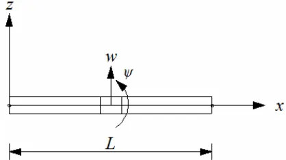
Fig. 1 shows the coordinate system used in the following formulation. The displacement components in x and z directions can be respectively written as a function of coordinate x and time t as
u = - zψ (x,t) (11a)
w = w(x,t) (11b)
where u is the axial displacement of a material point at coordinate (x, z), w is the transverse displacement (deflection) of the neutral axis and ψ is the rotation of the cross-section.
Figure 1. Coordinate system, deflection and rotation of the beam
Using the small-strain and displacement equations for general solids, Eqs. (11a) and (11b) give the nonzero strain components:
εxx = - zψ,x (12a)
γxz = w,x - ψ (12b)
where εxx is the normal strain in x direction and γxz is
the transverse shearing strain. The commas denote the first partial derivatives with respect to the variable next to it (i.e. x).
The variational equation of motion of the beam can be derived using Hamilton’s principle [12], viz.
(
)
strain energy, the kinetic energy, and the work of external forces, respectively. The strain energy is given as sectional area of the beam respectively, and
xx
is the vector of normal and shearing stresses, and
xx
The kinetic energy of the beam is given as beam material. The dots signify the first partial derivatives with respect to the time variable t. Substituting Eqs. (11a) and (11b) and integrating over the cross-section, Eq. (17) can be expressed as
2 2
Finally, the work of external forces is given as.
0 0
L L
W =
∫
w q dx+∫
ψ m dx (19)in which q and m are the distributed forces and moments along the length of the beam.
Substituting Eq. (16), Eq. (18) and Eq. (19) into Eq. (13), applying the variational operations, and applying Hamilton’s principles lead to the variational equation (or the weak form) for the Timoshenko beam as follows,
The double dots signify the second derivatives with respect to time t.
The bending moment and shear force along the beam can be calculated from the deflection w and rotation ψ as follows:
,x
M =EIψ (21)
(
,x)
Q=kGA w −ψ (22)
Formulation of Kriging-based Timoshenko Beam Element
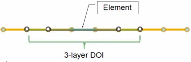
Suppose a beam is divided into a number of finite elements. For each element, KI is constructed based upon a set of nodes in a DOI including the element itself and a predetermined number of neighboring elements (see Wong and Kanok-Nukulchai [8] for detailed explanations). Consider now an element with its DOI including n nodes. The displacement components over the element are approximated by KI as follows:
shape functions, which are obtained by solving Kriging equations, Eqs. (4).
Entering the approximated displacement functions Eqs. (23a) and (23b) into the variational equation, Eq. (20), leads to the discrete equation of motion for Timoshenko beam element, i.e.
( )
t kd( ) ( )
t f tis the element consistent mass matrix,d&& is the element nodal acceleration vector,
dx
is the element stiffness matrix, and
0 0
L L
q dx ψm dx
=
∫
w +∫
f N N (24d)
is the element equivalent nodal force vector. Note that the size of the matrices m and k, d, and f depends on the number of nodes in the DOI, n. For static problems, Eq. (24a) simply reduces to
kd = f (25)
The integrations in Eqs. (24b), (24c), and (24d) are evaluated using Gauss quadrature. It is well known in the conventional FEM that if the stiffness matrix, Eq. (24c), is evaluated using full integration, then the element becomes too stiff for thin beams (shear locking phenomenon, see e.g. Hughes et al. [15] and Reddy [16]). One of the techniques to overcome the shear locking is the selective-reduced integration (SRI), in which the stiffness matrix is evaluated using full integration for the bending term (the first term in the right-hand side of Eq. (24c)) and using reduced integration for the shearing term (the second term in the right-hand side of Eq. (24c)). The effectiveness of the SRI technique to eliminate the shear locking in the Kriging-based Timoshenko beam is investigated in this study through a series of numerical tests.
Using the finite element assembly procedure, one can obtain the global discretized equation for the beam vibration as follows:
( )
t KD( ) ( )
t Ft DM&& + = (26)
where M and K are the global mass and stiffness matrices, respectively, D is the global nodal displacement vector, D&& is the global nodal acceleration vector, and F is the global nodal force vector. The equations for static and undamped free-vibration problems can be respectively written as
K D = F (27)
The free vibration of a structure with the natural frequency
ω
can be written as( )
= sin(
ωt+ϕ)
0D t
D (29)
where D0 is the amplitude of the vibration and φ is the phase angle. Entering Eq. (29) into Eq. (28) leads to the eigen equation
(K ―ω2M)D0 = 0 (30)
where D0 is a vector of eigenvalues, which is the mode shape of vibration, corresponding to an eigenvector ω2.
Numerical Results
The performance of the developed Kriging-based Timoshenko beam element was tested using a number of different static and free-vibration problems. In the following, for the sake of brevity, only the results for the beam element with the K-FEM options of the cubic basis, three-layer DOI (Fig. 2), and Gaussian correlation function (P3-3-G) are presented (see Syamsoeyadi [17] for the compre-hensive results). The issues considered include the shear locking phenomenon, the accuracy and the convergence of the displacements, bending moments, shear forces, and natural frequencies.
Firstly, the appropriate range for the correlation parameter θ and the efficient number of Gaussian sampling points for evaluating the integrations in Eqs. (24b), (24c) and (24d) were determined by conducting a series of numerical tests. The tests for finding the lower bound and the upper bound of θ satisfying Eqs. (10a) and (10b) revealed that for the beam element with Kriging option P3-3-G, the lower and upper bound values for θ are 10-4 and 1.9, respectively. In the subsequent analyses the parameter θ was taken to be equal to 1, which was nearly the mid-value between the lower and upper bounds.
To obtain an accurate yet efficient number of the integration sampling points, a cantilever beam subjected to triangular-distributed load as shown in Fig. 3 was analyzed using different number of sampling points for evaluating the stiffness matrices,
Nsamp. Subsequently, it was analyzed with different number of sampling points for evaluating the force vector, Nbody,. The free-end deflection of the beam was observed and compared to the exact solution [12], viz.
Figure 2. Three-layer DOI of a typical 1D element
4 0 t
5 1
12 q L w
EI φ
⎛ ⎞
= ⎜ + ⎟
⎝ ⎠ (31a)
2
1
(12 11 ) 5
h L φ= + ν ⎛ ⎞⎜ ⎟
⎝ ⎠ (31b)
Where qo, L, E, I, φ, v, and h are respectively the
value of the triangular load at the clamped end, the length, the modulus of elasticity, the moment of inertia, the ratio of bending stiffness to shearing stiffness, Poisson’s ratio and the thickness of the beam.
The results were presented in Tables 1 and 2. The tables show that at least two sampling points are needed to yield accurate integrations. In the subsequent analyses Nsamp was taken to be equal to 3 while Nbody was taken to be equal to 2. In the case where the SRI technique was employed, the number of sampling points for the bending term was 3 while that for the shearing term was 1.
Shear Locking
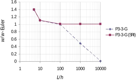
Shear locking is a phenomenon where the beam element is excessively stiff for the range of very small thickness (or the length-to-thickness ratio, L/h, is very large). To observe this phenomenon, a clamped-clamped beam with L = 10 m, E = 2000 kN/m2, k = 0.84967, v = 0.3, subjected to uniformly-distributed load, q=1 kN/m, was analyzed using eight elements. The height of the beam was varied from thick, L/h=5, up to extremely thin, L/h=10000.
Figure 3. Cantilever beam (E=2000 kN/m2, k=0.84967, v=0.3) subjected to unit triangular distributed load (kN/m), divided into eight equal finite elements
Table 1. Relative displacement errors for different number of sampling points on stiffness matrix (in this case Nbody = 2)
Nsamp Relative error (%)
1 2.23034 2 0.96674 3 0.96674 4 0.96674
Table 2. Relative displacement errors for different number of sampling points on equivalent nodal force vector (in this case Nsamp = 2)
Nbody Relative error (%)
0
1 10 100 1000 10000
L/h
Figure 4. Normalized deflection at the mid-span of the beam for different length-to-thickness ratios
The deflection at the mid-span was observed and normalized to the Euler-Bernoulli beam solution, i.e.
wEuler =
384EI
qL4
(32)
Theoretically, as the beam becomes very thin, the solution of Timoshenko beam theory will converge to the solution of Euler-Bernoulli beam theory. The results of the analyses were presented in Fig. 4 for the cases of using full integration, P3-3-G, and selective-reduced integration, P3-3-G (SRI). The figure shows that the element with full integration suffers shear locking while the element with SRI indicates no locking. Thus, the SRI technique is effective to eliminate the shear locking. This finding confirms the conclusion in the previous study [18]. Note that the SRI technique is also applicable for Kriging-based rectangular Reissner-Mindlin plate elements [18] but it is not applicable for triangular elements [10].
Accuracy and Convergence
To study the accuracy and convergence of the static solutions of the beam elements using 3-G and P3-3-G SRI, the beam subjected to triangular-distributed load (Fig. 3) was analyzed with the parameter E=1000 kN/m2, I=0.020833 m4, A=1 m2,
G=384.61 kN/m2, k=0.84967, v=0.3, L=4 m, L/h=8. The beam was divided into 2, 4, 8, and 16 elements. The deflections at the free end, the bending moments and the shearing forces at the clamped end were observed. The results were normalized with respect to their respective exact solutions and presented in Tables 3-5 together with the results of the superconvergent beam element of Friedman and Kosmatka (F&K) [12]. The tables show that both P3-3-G and P3-P3-3-G (SRI) can produce very accurate displacements and reasonably accurate moments. The element with P3-3-G gives slightly better results than the element with SRI. The shearing forces directly calculated from the shearing strains (Eq. 22), however, cannot produce accurate results. The use of SRI worsen the shearing forces. It is worthy to note
that this fact is also true for the traditional Timoshenko beam element [19]. It is interesting to notice that the results using full integration for the displacement and moment, converge from below, while those using SRI converge from above. This is because the use of SRI makes the stiffness matrix becomes ‘less stiff’ than the actual.
Free Vibration
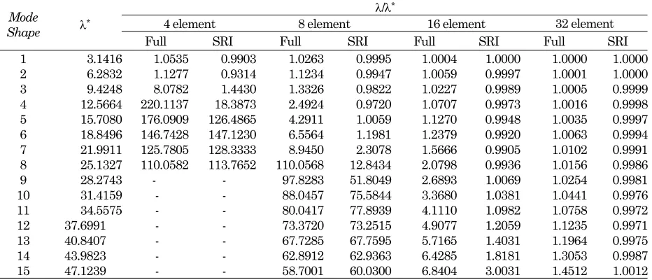
To investigate the accuracy and convergence of the natural frequency solutions from the beam element with P3-3-G and P3-3-G (SRI), free vibrations of a thick and a very thin simply-supported beams were considered. The beam parameters are L=10 m, the width b=1 m, E= 2x10⁹ N/m2, ν=0.3, ρ=10 kg/m3,
L/h=5 for the thick beam and L/h=1000 for the very thin beam. The beams were divided into 4, 8, 16, and 32 elements. The resulting natural frquencies were expressed in the form of non-dimensional frequency parameter, i.e.
where λi is the non-dimensional frequency parameter,
ωi is the angular natural frequency of the vibration
mode-i and m is the mass per unit length. For the thick beam, the convergent solutions of the pseudospectral method [20] were taken to be the reference solutions to assess the accuracy. Whilst for the very thin beam, the exact solutions of the Euler-Bernoulli beam [18] were used as the reference solutions. The normalized results of the analyses using full integration and SRI were presented in Tables 6 and 7 together with the reference solutions.
Table 3. Deflections at the free end normalized to the deflection of exact solution
Number of
elements P3-3-G P3-3-G (SRI) F&K
4 0.9998 1.0042 1
8 0.9999 1.0005 1
16 0.9999 1.0000 1
Table 4. Bending moments at the clamped end normalized to the bending moment of exact solution
Number of
elements P3-3-G P3-3-G (SRI) F&K
4 0.9350 1.0778 0.96
8 0.9924 1.0441 1
16 0.9993 1.0217 1
Table 5. Shearing forces at the clamped end normalized to the shearing force of exact solution
Number of
elements P3-3-G P3-3-G (SRI) F&K
4 1.6338 4.1432 0.8
8 1.1146 1.8706 0.9
The tables demonstrate that for the case of thick beam the performance of the elements is excellent, both with full and reduced integrations. For very thin beams, a very fine mesh is needed to achieve good accuracy for high mode frequencies. The element with SRI outperforms the element with full integration for the case of thin beam.
Conclusions
Kriging-based Timoshenko beam elements have been developed and tested in the static and free vibration problems. The test results show that the shear locking can be eliminated using the SRI technique. The elements, both with full and reduced integrations, can produce accurate displacement, bending moment, and natural frequencies. For thick
and not very thin beams, the element with full integration gives better overall results while for very thin beams, the element with SRI is better. The shearing forces directly calculated from the shearing strains, however, are not accurate. While the SRI technique works well for eliminating the shear locking, the use of this technique worsen the shearing force results. Alternative methods to eliminate the shear locking needs to be studied in the future research.
References
1. Gu, L., Moving Kriging Interpolation and Element-Free Galerkin Method, International Journal for Numerical Methods in Engineering, John Wiley and Sons, 56 (1), 2003, pp. 1-11.
Table 6. Normalized frequency parameter for the thick beam (L/h=5)
λ/λ*
4 element 8 element 16 element 32 element Mode
Shape λ
*
Full SRI Full SRI Full SRI Full SRI 1 3.0453 1.0080 0.9949 1.0047 1.0041 1.0047 1.0046 1.0047 1.0047 2 5.6716 1.0697 0.9485 1.0144 1.0086 1.0139 1.0134 1.0139 1.0138 3 7.8395 1.1472 1.1091 1.0263 1.0050 1.0224 1.0211 1.0224 1.0222 4 9.6571 1.4321 1.4186 1.0436 0.9973 1.0294 1.0264 1.0293 1.0289 5 11.2220 1.2654 1.2406 1.0682 1.0079 1.0352 1.0292 1.0347 1.0342 6 12.6022 1.1991 1.1673 1.0945 1.0666 1.0402 1.0295 1.0390 1.0382 7 13.0323 1.3375 1.2409 1.0612 1.0649 1.0612 1.0603 1.0612 1.0608 8 13.4443 1.3814 1.3005 1.0562 1.0556 1.0562 1.0480 1.0562 1.0555 9 13.8433 - - 1.0916 1.0915 1.0452 1.0355 1.0425 1.0413 10 14.4378 - - 1.0830 1.1217 1.0467 1.0421 1.0467 1.0460 11 14.9766 - - 1.0859 1.1063 1.0506 1.0333 1.0453 1.0436 12 15.6676 - - 1.1166 1.1104 1.0380 1.0339 1.0380 1.0373 13 16.0241 - - 1.1747 1.1640 1.0570 1.0378 1.0476 1.0453 14 16.9584 - - 1.2066 1.1752 1.0310 1.0279 1.0310 1.0304 15 17.0019 - - 1.4033 1.3669 1.0644 1.0489 1.0495 1.0465 Note: * Convergent solution from the the pseudospectral method [20]
Table 7. Normalized frequency parameter for the very thin beam (L/h=1000)
λ/λ*
4 element 8 element 16 element 32 element Mode
Shape λ
*
2. Plengkhom, K. and Kanok-Nukulchai, W., An Enhancement of Finite Element Method with Moving Kriging Shape Functions, International
Journal of Computational Methods, World
Scientific, 2 (4), 2005, pp. 451-475.
3. Wong, F.T. and Kanok-Nukulchai, W., Kriging-based Finite Element Method for Analyses of Reissner-Mindlin Plates, Proceedings of the Tenth East-Asia Pacific Conference on Structural
Engineering and Construction, Emerging
Trends: Keynote Lectures and Symposia, 3-5 August 2006, Bangkok, Thailand, Asian Institute of Technology, pp. 509-514.
4. Wong, F.T. and Kanok-Nukulchai, W., On Alleviation of Shear Locking in the Kriging-based Finite Element Method, Proceedings of International Civil Engineering Conference “Towards Sustainable Engineering Practice”, 25-26 August 2006, Surabaya, Indonesia, Petra Christian University, pp. 39-47.
5. Wong, F.T. and Kanok-Nukulchai, W., On the Convergence of the Kriging-based Finite Element Method, International Journal of Computational Methods, World Scientific, 6 (1), 2009, pp. 93-118.
6. Kanok-Nukulchai, W. and Wong, F.T., A Finite Element Method using Node-based Interpolation,
Proceedings of the Third Asia-Pacific Congress on Computational Mechanics and the Eleventh International Conference on Enhancement and Promotion of Computational Methods in Engineering and Sciences, 3-6 December 2007, Kyoto, Japan, APACM and EPMESC, Paper No. PL3-3.
7. Kanok-Nukulchai, W. and Wong, F.T., A Break-Through Enhancement of FEM using Node-based Kriging Interpolation, IACM Expressions, International Association for Computational Mechanics, 23, June 2008, pp. 24-29.
8. Wong, F.T. and Kanok-Nukulchai, W., Kriging-based Finite Element Method: Element-by-Element Kriging Interpolation, Civil Engineering Dimension, Petra Christian University, 11(1), 2009, pp. 15-22.
9. Wong, F.T. and Kanok-Nukulchai, W., A Kriging-based Finite Element Method for Analyses of Shell Structures, Proceedings of the Eighth World Congress on Computational Mechanics and the Fifth European Congress on Computational
Methods in Applied Sciences and Engineering, 30 June-4 July 2008, Venice, Italy, IACM and ECCOMAS, Paper No. a1247.
10. Wong, F.T., Kriging-based Finite Element Method for Analyses of Plates and Shells, Asian Institute of Technology Dissertation No. St 09 01, Asian Institute of Technology, Bangkok, Thailand, 2009.
11. Sommanawat, W. and Kanok-Nukulchai, W., Multiscale Simulation Based on Kriging-Based Finite Element Method, Interaction and Multiscale Mechanics, Techno Press, 2 (4), 2009, pp. 387-408.
12. Friedman, Z. and Kosmatka, J.B., An Improved Two-node Timoshenko Beam Finite Element,
Computers & Structures, 47(3), 1993, pp. 473-481.
13. Olea, R.A., Geostatistics for Engineers and Earth Scientists, Kluwer Academic Publishers, Boston, USA, 1999.
14. Wackernagel, H., Multivariate Geostatistics, 2nd edition, Springer, Berlin, Germany, 1998.
15. Hughes, T.J.R., Taylor, R.L. and Kanok-Nukulchai, W., A Simple and Efficient Finite Element for Plate Bending, International Journal for Numerical Methods in Engineering, John Wiley and Sons,11, 1977, pp. 1529-1543.
16. Reddy, J. N., An Introduction to the Finite Element Method., 3th edition, McGraw-Hill, Singapore, 2006.
17. Syamsoeyadi, H., Development of Kriging-based Timoshenko Beam Element for Static and Free Vibration Analyses (in Indonesian language), Petra Christian University Undergraduate Thesis No. 11011660/SIP/2009, Petra Christian University, Surabaya, Indonesia, 2009.
18. Wicaksana, C., Dynamic Analysis using Kriging-based Finite Element Methods,Asian Institute of Technology Thesis No. St 06 15, Asian Institute of Technology, Bangkok, Thailand, 2006.
19. Prathap, G., The Finite Element Method in
Structural Mechanics, Kluwer Academic
Publisher, Dordrecht, Netherlands, 1993.
20. Lee, J. and Schultz, W.W., Eigenvalue Analysis of Timoshenko Beams and Axisymmetric Mindlin Plates by the Pseudospectral Method,