6JG&GXGNQRGTŏU)WKFG
(QWTVJ'FKVKQP
,CP#ZGNUQP
Copyright 1999-2009 by Janet L. Axelson
All rights reserved. No part of the contents of this book, except the program code, may be reproduced or transmitted in any form or by any means without the written permission of the publisher. The program code may be stored and executed in a computer system and may be incorporated into computer pro-grams developed by the reader.
The information, computer programs, schematic diagrams, documentation, and other material in this book are provided “as is,” without warranty of any kind, expressed or implied, including without limitation any warranty concerning the accuracy, adequacy, or completeness of the material or the results obtained from using the material. Neither the publisher nor the author shall be responsible for any claims attributable to errors, omissions, or other inaccuracies in the material in this book. In no event shall the publisher or author be liable for direct, indi-rect, special, incidental, or consequential damages in connection with, or arising out of, the construction, performance, or other use of the materials contained herein.
Many of the products and company names mentioned herein are the trademarks of their respective holders. PIC and MPLAB are registered trademarks of Micro-chip Technology Inc. in the U.S.A. and other countries. PICBASIC PRO is a trademark of Microchip Technology Inc. in the U.S.A. and other countries.
Published by Lakeview Research LLC, 5310 Chinook Ln., Madison WI 53704 www.Lvr.com
Distributed by Independent Publishers Group (ipgbook.com). 14 13 12 11 10 9 8 7 6 5 4 3 2 1
+
PVTQFW
E
VKQP
Z
XKK
75$
$
C
UK
E
U
7UGUCPF.KOKVU
Benefits for Users . . . 2
Benefits for Developers . . . 5
What USB Can’t Do . . . 7
USB versus Ethernet . . . 10
USB versus IEEE-1394. . . 11
'XQNWVKQPQHCP+PVGTHCEG USB 1.0 . . . 11
USB 1.1 . . . 12
USB 2.0 . . . 12
USB 3.0 . . . 13
USB On-The-Go . . . 14
Bus Speed Considerations . . . 16
Terminology . . . 18
&KXKUKQPQH.CDQT The Host’s Duties . . . 20
The Device’s Duties. . . 22
Bus Speeds and Data Throughput . . . 24
&GXGNQRKPIC&GXKEG Components . . . 25
Tools for Developing. . . 25
Steps in Developing a Project . . . 25
75$(TGSWGPVN[#UMGF3WGUVKQPU Features . . . 27
Compatibility . . . 28
Cables . . . 29
Power . . . 30
+
PUKFG
75$
6T
C
PU
H
GTU
6TCPUHGT$CUKEU The Essentials . . . 31Purposes for Communication . . . 32
Managing Data on the Bus . . . 33
'NGOGPVUQHC6TCPUHGT Endpoints: the Source and Sink of Data . . . 34
Transaction Types . . . 35
Pipes: Connecting Endpoints to the Host . . . 36
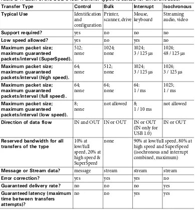
Types of Transfers . . . 36
Stream and Message Pipes . . . 38
Initiating a Transfer. . . 39
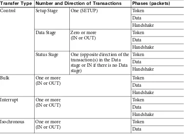
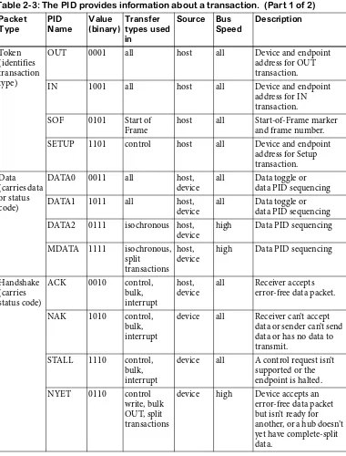
75$6TCPUCEVKQPU Transaction Phases . . . 41
Packet Sequences . . . 44
Timing Constraints and Guarantees . . . 45
Reporting the Status of Control Transfers. . . 49
Error Checking . . . 50
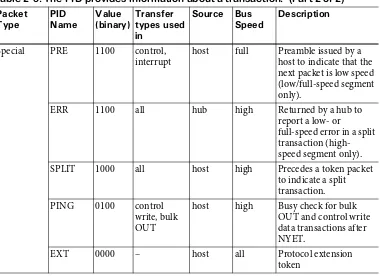
5WRGT5RGGF6TCPUCEVKQPU Packet Types. . . 53
Transferring Data . . . 54
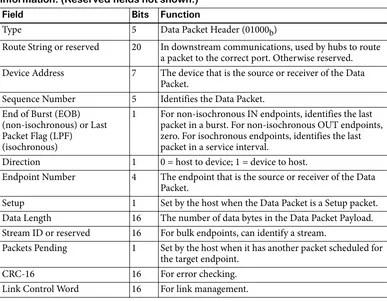
Link Management Packets . . . 59
#
6T
C
PU
H
GT
6
[
RG
H
QT
'XGT
[2
WTRQUG
%QPVTQN6TCPUHGTU Availability . . . 61Structure. . . 62
Data Size . . . 68
Speed . . . 68
Detecting and Handling Errors. . . 69
Device Responsibilities . . . 70
$WNM6TCPUHGTU Availability . . . 71
Structure. . . 71
Data Size . . . 74
Speed . . . 74
Detecting and Handling Errors. . . 75
Device Responsibilities . . . 75
+PVGTTWRV6TCPUHGTU Availability . . . 76
Structure. . . 76
Data Size . . . 77
Speed . . . 78
Detecting and Handling Errors. . . 79
Device Responsibilities . . . 80
+UQEJTQPQWU6TCPUHGTU Availability . . . 80
Structure. . . 80
Data Size . . . 83
Speed . . . 84
Detecting and Handling Errors. . . 85
Device Capabilities . . . 86
Host Capabilities . . . 87
Host Latencies . . . 88
'PWOGT
C
VKQP
*
Q
Y
VJG
*
QUV
.
G
C
TPU
CD
QWV
&GXK
E
GU
6JG2TQEGUU Enumeration Steps . . . 90Device Removal. . . 96
Tips for Successful Enumeration . . . 96
&GUETKRVQTU Types. . . 97
Device . . . 99
Device_Qualifier . . . 102
Configuration . . . 103
Other_Speed_Configuration . . . 105
Interface Association . . . 105
Interface . . . 107
Endpoint . . . 110
SuperSpeed Endpoint Companion . . . 112
String . . . 113
Binary Object Store and Device Capability . . . 114
Other Standard Descriptors . . . 115
Microsoft OS Descriptors . . . 116
Updating Descriptors to USB 2.0 . . . 116
%QPVTQN
6T
C
PU
H
GTU
5VTW
E
VWTGF
4
G
S
WGUVU
H
QT
%TKVK
EC
N
&
C
V
C
'NGOGPVUQHC%QPVTQN6TCPUHGT Setup Stage . . . 118Data Stage . . . 119
Status Stage . . . 121
Handling Errors. . . 122
Clear Feature . . . 127
Set Feature . . . 128
Set Address . . . 129
Get Descriptor . . . 130
Set Descriptor. . . 131
Get Configuration . . . 132
Set Configuration . . . 132
Get Interface. . . 133
Set Interface . . . 133
Synch Frame. . . 134
Set SEL. . . 135
Set Isochronous Delay . . . 135
1VJGT4GSWGUVU Class-Specific Requests . . . 136
Vendor-Defined Requests . . . 136
%JKR
%JQK
E
GU
%QORQPGPVUQHC75$&GXKEG Inside a USB 2.0 Controller . . . 138Other Device Components . . . 139
5KORNKH[KPI&GXKEG&GXGNQROGPV Device Requirements . . . 142
Chip Documentation . . . 143
Driver Choices . . . 144
Debugging Tools . . . 144
75$/KETQEQPVTQNNGTU Microchip PIC18F4550 . . . 148
Cypress EZ-USB. . . 152
ARM . . . 156
%QPVTQNNGTUVJCV+PVGTHCEGVQ%27U ST-NXP Wireless ISP1582. . . 157
PLX Technology NET2272 . . . 157
Approved Specifications. . . 164
Elements of a Class Specification . . . 164
&GHKPGF%NCUUGU Audio . . . 165
Communications . . . 169
Content Security . . . 176
Device Firmware Upgrade . . . 177
Human Interface . . . 180
IrDA Bridge. . . 183
Mass Storage . . . 184
Personal Healthcare . . . 189
Printer . . . 190
Smart Card . . . 192
Still Image Capture . . . 194
Test and Measurement . . . 197
Video. . . 198
+ORNGOGPVKPI0QPUVCPFCTF(WPEVKQPU Choosing a Driver . . . 203
Using a Generic Driver . . . 203
Converting from RS-232 . . . 204
Converting from the Parallel Port . . . 204
PC-to-PC Communications . . . 205
*
Q
Y
VJG
*
QUV
%QOOWPK
EC
VGU
&GXKEG&TKXGTU The Layered Driver Model . . . 209User and Kernel Modes . . . 210
+PUKFGVJG.C[GTU Applications. . . 212
User-mode Client Drivers . . . 213
Kernel-mode Client Drivers. . . 213
User-mode Drivers . . . 218
Testing Tools . . . 218
7UKPI)7+&U Device Setup GUIDs . . . 219
Device Interface GUIDs . . . 220
/C
V
E
JKP
IC
&TKXGT
VQ
C
&GXK
E
G
7UKPIVJG&GXKEG/CPCIGT Viewing Devices . . . 224Property Pages . . . 225
&GXKEG+PHQTOCVKQPKPVJG4GIKUVT[ The Hardware Key . . . 227
The Class Key. . . 229
The Driver Key. . . 231
The Service Key . . . 231
+PUKFG+0((KNGU Structure and Syntax. . . 232
Device-specific Values. . . 235
7UKPI&GXKEG+FGPVKHKECVKQP5VTKPIU Finding a Match . . . 238
When to Provide an INF File . . . 239
6QQNUCPF&KCIPQUVKE#KFU Tips for Using INF Files. . . 240
What the User Sees. . . 241
&GVG
E
VKP
I
&GXK
E
GU
#$TKGH)WKFGVQ%CNNKPI#2+(WPEVKQPU Managed and Unmanaged Code. . . 244Managing Data. . . 248
(KPFKPI;QWT&GXKEG Obtaining the Device Interface GUID . . . 252
Requesting a Pointer to a Device Information Set. . . 254
Identifying a Device Interface . . . 255
Requesting a Structure with the Device Path Name . . . 258
Extracting the Device Path Name . . . 261
Closing the Handle . . . 264
&GVGEVKPI#VVCEJOGPVCPF4GOQXCN About Device Notifications . . . 265
Registering for Device Notifications . . . 265
Capturing Device Change Messages . . . 269
Reading Device Change Messages . . . 270
Retrieving the Device Path Name in the Message . . . 271
Stopping Device Notifications . . . 275
*
WO
C
P
+
PVGT
HCE
G
&GXK
E
GU
7UKP
I
%QPVTQN
C
PF
+
PVGTTWRV
6T
C
PU
H
GTU
9JCVKUC*+&! Hardware Requirements . . . 279Firmware Requirements. . . 280
&GUETKRVQTU The HID Interface . . . 285
HID Class Descriptor . . . 286
Report Descriptors. . . 286
*+&URGEKHKE4GSWGUVU Get Report . . . 290
Get Idle . . . 290
Get Protocol . . . 291
Set Report . . . 291
Set Idle . . . 292
Set Protocol . . . 292
6TCPUHGTTKPI&CVC Writing Firmware . . . 293
Tools . . . 293
*
WO
C
P
+
PVGT
HCE
G
&GXK
E
GU
4
GRQTVU
4GRQTV5VTWEVWTG Using the HID Descriptor Tool . . . 296Control and Data Item Values. . . 296
Collections . . . 302
6JG)NQDCN+VGO6[RG Identifying the Report . . . 303
Describing the Data’s Use. . . 304
Converting Units . . . 306
Converting Raw Data . . . 307
Describing the Data’s Size and Format . . . 311
Saving and Restoring Global Items . . . 311
6JG.QECN+VGO6[RG Physical Descriptors . . . 314
Padding . . . 314
*
WO
C
P
+
PVGT
HCE
G
&GXK
E
GU
*
QUV
#
RRNK
EC
VKQP
*++(WPEVKQPU Requesting Information about the HID . . . 317Sending and Receiving Reports. . . 317
Providing and Using Report Data. . . 318
Managing HID Communications. . . 319
+FGPVKH[KPIC&GXKEG Reading the Vendor ID and Product ID. . . 321
Getting a Pointer to Device Capabilities . . . 323
Getting the Device’s Capabilities . . . 324
Getting the Capabilities of the Buttons and Values. . . 327
5GPFKPICPF4GEGKXKPI4GRQTVU Sending an Output Report to the Device . . . 328
Reading an Input Report from the Device . . . 330
Writing a Feature Report to the Device . . . 339
Reading a Feature Report from a Device. . . 341
%CRCDKNKVKGUCPF.KOKVU
Device Requirements. . . 345
Host Requirements . . . 346
Device Firmware . . . 346
Assigning the WinUSB Driver. . . 349
#EEGUUKPIVJG&GXKEG Obtaining a WinUSB Handle . . . 350
Requesting an Interface Descriptor . . . 352
Identifying the Endpoints . . . 354
Setting Pipe Policies. . . 359
Writing Data via Bulk and Interrupt Transfers . . . 364
Reading Data via Bulk and Interrupt Transfers . . . 366
Using Vendor-defined Control Transfers. . . 368
Closing Communications . . . 371
#
NN
#D
QWV
*
W
D
U
75$ The Hub Repeater. . . 376The Transaction Translator . . . 377
The Hub Controller . . . 383
Speed. . . 383
Maintaining Active Links . . . 385
75$ Bus Speeds. . . 386
Components . . . 386
Managing Traffic. . . 387
6JG*WD%NCUU Hub Descriptors . . . 388
Hub Class Requests . . . 388
Voltages . . . 390
Using Bus Power . . . 390
Power Needs. . . 392
Informing the Host. . . 393
Battery Charging . . . 393
*WD2QYGT Power Sources. . . 396
Over-current Protection . . . 397
Power Switching . . . 399
5CXKPI2QYGT USB 2.0 Link Power Management . . . 399
Suspend State . . . 400
Sleep State . . . 401
SuperSpeed Power Management. . . 402
Power Management under Windows . . . 407
6GUVKP
IC
PF
&G
D
W
II
KP
I
6QQNU Hardware Protocol Analyzers . . . 410Software Protocol Analyzers . . . 412
Traffic Generators. . . 414
6GUVKPI Compliance . . . 415
Windows Logo . . . 422
2CEM
GVU
QP
VJG
$WU
75$ Low Speed and Full Speed Bus States . . . 425High Speed Bus States . . . 428
Data Encoding . . . 430
Staying Synchronized . . . 431
Timing Accuracy . . . 432
Packet Format. . . 433
Inter-Packet Delay . . . 434
Encoding . . . 436
Link Layer . . . 437
Reset . . . 438
6JG
'NG
E
VTK
EC
N
C
PF
/
G
E
J
C
PK
EC
N
+
PVGT
HCE
G
75$6TCPUEGKXGTU Cable Segments . . . 440Low- and Full-Speed Transceivers . . . 441
High-speed Transceivers . . . 444
Signal Voltages . . . 448
75$%CDNGU Conductors . . . 450
Connectors . . . 451
Detachable and Captive Cables . . . 453
Cable Length . . . 454
Bus Length . . . 455
Inter-Chip Connections. . . 455
75$ Transmitters and Receivers . . . 457
Cables . . . 457
'PUWTKPI5KIPCN3WCNKV[ Sources of Noise . . . 462
Balanced Lines. . . 462
Twisted Pairs . . . 463
Shielding . . . 464
Edge Rates . . . 464
Isolated Interfaces . . . 465
)QKPI9KTGNGUU Certified Wireless USB . . . 466
Cypress WirelessUSB. . . 466
Capabilities and Limits . . . 472
The OTG Connector . . . 472
The A-Device and B-Device . . . 472
Requirements for an OTG Device . . . 473
The OTG Descriptor . . . 479
Feature Codes for HNP . . . 480
1VJGT*QUV1RVKQPU Requirements . . . 481
Device Ports . . . 481
%QPVTQNNGT%JKRU Microcontrollers . . . 483
Interface Chips . . . 484
This book is for developers who are involved with designing or programming devices that use the Universal Serial Bus (USB) interface. If you are a hardware designer, if you write firmware that resides inside USB devices, or if you write applications that communicate with devices, this book is for you.
USB is versatile enough to serve a multitude of device functions. Familiar USB peripherals include mice, keyboards, drives, printers, speakers, and cameras. USB is also suitable for data-acquisition units, control systems, and other devices with specialized functions, including one-of-a-kind designs. The right choices of device hardware, software drivers and development tools and tech-niques can ease the path to designing devices that perform their functions with-out error or user aggravation. This book will guide you along the way.
9JCVŏU+PUKFG
These are some of the questions this book answers:
• How do USB devices communicate? I don’t attempt to restate everything in the USB specifications. Instead, my focus is on what you need to know to develop devices that communicate efficiently and reliably.
• How can I decide if my device should use a USB interface? Find out whether your device should use USB or another interface. If the choice is USB, you’ll learn how to decide which of USB’s four speeds—including USB 3.0’s SuperSpeed—and which of USB’s four transfer types are appropriate for your application.
• What controller chip should my device use? Every USB device contains an intelligent controller to manage USB communications. Dozens of silicon providers offer controller chips with different architectures and abilities. This book will help you select a controller based on your project’s needs, your budget, and your preferences for chip architecture, programming lan-guages, and tools.
• How can applications communicate with my devices? On a PC, an application accesses a USB device by communicating with a driver the operating system has assigned to the device. You’ll learn if your device can use a class driver provided by the host’s operating system. For devices that don’t fit a sup-ported class, you can explore options such as Microsoft’s WinUSB driver, other generic drivers, and custom drivers. Example code shows how to detect and communicate with devices from Visual Basic and Visual C# applications.
• What firmware does my device need to support USB communications? Find out how to write firmware that enables your device to respond to USB requests and events and exchange data for any purpose.
• Does my device need its own power supply? The USB interface can provide power to devices, including charging current for battery-powered devices. Learn how to determine if a design can obtain all of its power from the bus, how to meet USB’s requirements for conserving power, and how to charge battery-powered devices from the bus.
both a USB device and a limited-capability host that accesses other USB devices.
• How can I ensure reliable communications? All devices must respond to requests and other events on the USB port. The host computer must detect attached devices, locate appropriate drivers, and exchange data with the devices. This book provides tips, example code, and information about debugging software and hardware to help with these tasks.
To understand the material in the book, it’s helpful to have some experience with digital logic, application programming for PCs and writing embedded code for peripherals. You don’t have to know anything about USB.
9JCVŏU0GY
The core of USB has remained much the same since the release of USB 1.0 in 1996. But the interface has expanded to support faster bus speeds, improved power management, more device classes, wireless communications, dual-role devices (device and host), and more. Plus, new and improved chips and devel-opment tools have eased the task of developing devices and software to access them.
This edition is revised and updated throughout. All new in the Fourth Edition is an introduction to USB 3.0 and the SuperSpeed bus. You’ll also learn how to use Microsoft’s WinUSB driver to access devices that perform vendor-specific functions. Topics with major updates include device-controller chips, technolo-gies for wireless USB communications, protocols for conserving power, and USB device classes.
I provide example code for applications in both Visual Basic and Visual C#. For device firmware, I discuss using both microengineering Labs’ PICBASIC PRO™ and Microchip Technology’s MPLAB® C compiler.
7RFCVGUCPF/QTG
To find out more about developing USB devices and the software that commu-nicates with them, I invite you to visit my USB Central page at www.Lvr.com. You’ll find code examples and links to articles, products, tools, and other infor-mation related to developing USB devices.
At the start of each code example, a sidehead indicates the programming lan-guage:
The .NET code is compatible with the .NET Framework Version 2.0 and later. Example applications are available for free download from www.Lvr.com.
5KFGJGCF 2TQITCOOKPI.CPIWCIG 2TQXKFGT
VB Visual Basic .NET Microsoft VC# Visual C# .NET Microsoft
PBP PICBASIC PRO microEngineering Labs, Inc. C18 MPLAB C compiler for
PIC18 CPUs
This book uses the abbreviations and symbols below to express quantities and units:
/WNVKRNKGTU
'NGEVTKECN
6KOG
5[ODQN &GUETKRVKQP /WNVKRNKGT
p pico 10-12
n nano 10-9
µ micro 10-6
m milli 10-3
k kilo 103
K kilo 210 (1024)
M mega 106 or 220 depending on context
G giga 109 or 230 depending on context
5[ODQN &GUETKRVKQP
A ampere
F farad
Ω ohm
V volt
5[ODQN &GUETKRVKQP
s second
&CVC
0WODGT5[UVGOU
Binary values have a trailing subscript “b”. Example: 10100011b. An exception is when it’s clear from the context that the values are binary. Example: Set bits 6..5 to 01.
Hexadecimal values have a trailing “h”. Example: A3h. All other values are decimal. Example: 163.
5[ODQN &GUETKRVKQP
in. inch
ft foot
m meter
5[ODQN &GUETKRVKQP
b bit
B byte
thank.
My technical reviewers provided feedback that helped make the book as com-plete and accurate as possible. With that said, every error in this book is mine and mine alone. A big thanks to Paul E. Berg, Greg Burk, Robert Dunstan, John Garney, Bill Jacobus, Kosta Koeman, and Matt Leptich.
Others I want to thank for their support are Phyllis Brown of J. Gordon Elec-tronic Design, Michael DeVault of DeVaSys Embedded Systems, Traci Donnell of the USB-IF, David Flowers of Microchip Technology, Inc., Laurent Guin-nard of Ellisys, Tim Harvey of CWAV, Inc., Blake Henry of Bitwise Systems, John Hyde of usb-by-example.com, Rahman Ismail and Jeff Ravencraft of Intel Corporation, Dr. Bob Miller of Trace Systems, Inc., and Jeff Schmoyer of microEngineering Labs, Inc.
For their help with the previous editions this edition builds on, thanks to Joshua Buergel, Gary Crowell, Fred Dart, Wendy Dee, Lucio DiJasio, Keith Dingwall, Dave Dowler, Mike Fahrion, David Goll, John M. Goodman, Lane Hauck, David James, Christer Johansson, Geert Knapen, Alan Lowne, Jon Lueker, Brad Markisohn, Rich Moran, Bob Nathan, Walter Oney, Amar Rajan, Marc Reinig, Rawin Rojvanit, Glenn M. Roberts, Robert Severson, Craig R. Smith, and Dave Wright.
I hope you find the book useful and welcome your comments at[email protected].
75$
$CUKEU
At over two billion new installed units per year, USB is the most successful per-sonal-computer interface ever. Every recent PC has USB ports that can connect to keyboards, mice, game controllers, scanners, cameras, printers, drives, and more. USB is reliable, fast, versatile, power-conserving, inexpensive, and sup-ported by major operating systems. USB 3.0’s new SuperSpeed bus means USB is likely to continue to dominate as the interface of choice for an ever-expand-ing selection of peripherals.
This chapter introduces USB, including its advantages and limits, some history about the interface and recent enhancements to it, and a look at what’s involved in designing and programming a device with a USB interface.
7UGU
CPF
.KOKVU
To be successful, an interface has to please two audiences: the users who want to use the devices and the developers who design the hardware and write the code that communicates with the devices. USB has features to please both groups.
$GPG
H
KVU
H
QT
7UG
T
U
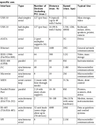
From the user’s perspective, the benefits of USB are ease of use, fast and reliable data transfers, low cost, and power conservation. Table 1-1 compares USB with other interfaces.
'CU[VQ7UG
Ease of use was a major design goal for USB, and the result is an interface that’s a pleasure to use for many reasons:
One interface for many devices. USB is versatile enough for just about any standard PC peripheral function. Instead of having a different connector and cable type for each peripheral function, one interface serves many.
Automatic configuration. When a user connects a USB device to a PC, the operating system detects the device and loads the appropriate software driver. The first time the device connects, the operating system may prompt the user to insert a disc with driver software, but other than that, installation is automatic. Users don’t need to reboot before using the device.
Easy to connect. A typical PC has multiple USB ports, and hubs make it easy to add ports without opening up the PC.
Convenient cables. USB connectors are small and compact compared to con-nectors used by other interfaces such as RS-232. To ensure reliable operation, the USB specification defines electrical requirements for cables. A cable seg-ment can be as long as 5 m depending on bus speed. With hubs, again depend-ing on bus speed, a device can be as far as 30 m from its host PC.
Wireless options. USB originated as a wired interface, but technologies are now available for wireless communications with USB devices.
Hot pluggable. Users can connect and disconnect a USB device whenever they want, whether or not the system and device are powered, without damaging the PC or device. The operating system detects when a device is attached and read-ies it for use.
Table 1-1: USB is more flexible than other interfaces, which often target a
USB 3.0 dual simplex serial
USB 2.0 half duplex serial
eSATA serial 2 (port
multiplier supports 16)
6 3G Drives
Ethernet serial 1024 1600 10G General network
communications IEEE-1394b
(FireWire 800)
serial 64 300 3.2G Video, mass
storage IEEE-488
(GPIB)
parallel 15 60 8M Instrumentation
I2C synchronous
serial
40 18 3.4M Microcontroller
communications Microwire synchronous
serial
8 10 2M Microcontroller
communications
50 31.5k Music, show
control
4000 10M Data acquisition and control systems
SPI synchronous
serial
8 10 2.1M Microcontroller
No power supply required (sometimes). The USB interface includes power-supply and ground lines that provide a nominal +5V from the PC or a hub. A device that requires up to 500 mA (USB 2.0) or 900 mA (USB 3.0) can draw all of its power from the bus instead of using a dedicated power supply. In contrast, devices that use other interfaces may have to provide a power supply inside the device or an external supply.
/WNVKRNG5RGGFU
USB supports four bus speeds: SuperSpeed at 5 Gbps, high speed at 480 Mbps, full speed at 12 Mbps, and low speed at 1.5 Mbps. SuperSpeed requires a USB 3.0 host controller in the host PC. USB 2.0 host controllers support low, full, and high speeds.
The bus speeds describe the rate that information travels on the bus. In addi-tion to applicaaddi-tion data, the bus must carry status, control, and error-checking information. Plus, multiple devices can share a bus. Thus, the data throughput for an individual device’s data is less than the bus speed. The USB protocols support data transfers at around 400 MB/s for SuperSpeed, 53 MB/s for high speed, 1.2 MB/s for full speed, and 800 B/s for low speed. Hardware and soft-ware limitations can result in lower real-world rates, however.
The USB 1.0 specification defined low and full speeds. Full speed was intended for most peripherals that had been using RS-232 (serial) and parallel ports. Full-speed data-transfer rates are comparable to the speeds of these earlier inter-faces. Mice tend to use low speed because the less stringent cable requirements allow flexible cables. Low-speed devices may have lower manufacturing cost due in part to cheaper cables. High speed became an option with the release of USB 2.0, and USB 3.0 defined SuperSpeed.
4GNKCDNG
+PGZRGPUKXG
Because the host computer provides most of the intelligence to control the interface, components for USB devices are inexpensive. A device with a USB interface is likely to cost the same or less than an equivalent device with a differ-ent interface.
2QYGT5CXKPI
Power-saving circuits and protocols reduce a device’s power consumption while keeping the device ready to communicate when needed. Reducing power con-sumption saves money, helps the environment, and for battery-powered devices, allows a longer time between recharges.
$GPG
H
KVU
H
QT
&
G
X
G
NQR
G
T
U
Many of the user advantages described above also make things easier for opers. For example, USB’s cable standards and error checking mean that devel-opers don’t have to worry about specifying cable characteristics or providing error checking in software.
Other advantages help the hardware designers who select components and design the circuits in devices and the programmers who write firmware embed-ded in the devices and software to communicate with devices.
The benefits result from the flexibility built into the USB protocol, the support in the controller chips and operating system, and the support available from the USB Implementers Forum.
8GTUCVKNG
USB’s four transfer types and four speeds make the interface feasible for many types of peripherals. USB has transfer types suited for exchanging large and small blocks of data, with and without time constraints. For data that can’t tol-erate delays, USB can guarantee bandwidth. These abilities are especially wel-come under Windows where accessing peripherals in real time is often a challenge. Although the operating system, device drivers, and application soft-ware can introduce unavoidable delays, USB makes it as easy as possible to achieve transfers that are close to real time even on desktop systems.
intention of communicating with line printers. USB makes no such assump-tions and is suitable for just about any peripheral type.
For communicating with common peripherals such as printers, keyboards, and drives, USB classes specify device requirements and protocols. Developers can program a device to conform to a class specification instead of having to rein-vent everything from the ground up.
1RGTCVKPI5[UVGO5WRRQTV
This book focuses on Windows programming for PCs, but other computers and operating systems also have USB support, including Linux and Apple Computer’s Macintosh. Some real-time kernels also support USB.
At the most basic level, an operating system that supports USB must do three things:
• Detect when devices are attached to and removed from the system.
• Communicate with newly attached devices to find out how to exchange data with them.
• Provide a mechanism that enables software drivers to pass communications between the USB hardware and applications that want to access USB peripherals.
At a higher level, operating-system support may also mean the inclusion of class drivers that enable applications to access specific types of devices. If the operat-ing system doesn’t include a driver appropriate for a specific device, the device vendor must provide the driver.
Microsoft continues to improve and add to the class drivers included with Win-dows. Supported device types include human interface devices (keyboards, mice, game controllers), speakers and other audio devices, modems, drives, still-image and video cameras, scanners, printers, and smart-card readers. Filter drivers can support device-specific features and abilities within a class. Applica-tions use Application Programming Interface (API) funcApplica-tions or other software components to access devices via their drivers.
Writers of USB device drivers for Windows can use Microsoft’s Windows Driver Foundation (WDF) model. The WDF provides a framework that sim-plifies the task of writing drivers.
&GXKEG5WRRQTV
On the device side, the hardware must include a controller chip that manages USB communications. The device is responsible for responding to requests that identify and configure the device and for reading and writing other data on the bus. Some controllers perform some functions entirely in hardware.
Many USB controllers are based on popular microcontroller architectures such as Intel Corporation’s 8051 or Microchip Technology’s PIC® with added hard-ware support for USB communications. Other controllers don’t contain a CPU but instead provide a serial or parallel interface to an external microcontroller. If you’re already familiar with a chip architecture that has a USB-capable variant, you don’t need to learn a new architecture. Most chip companies provide exam-ple code to help you get started.
75$+ORNGOGPVGTU(QTWO
The USB Implementers Forum, Inc., or USB-IF (www.usb.org), is the non-profit corporation founded by the companies that developed the USB specification.
The USB-IF’s mission is to support the advancement and adoption of USB technology. To that end, the USB-IF offers information, tools, and testing sup-port. The information includes the specification documents, white papers, FAQs, and a Web forum. The tools include software and hardware to help in developing and testing products. The support for testing includes compliance tests to verify proper operation and compliance workshops where developers can have their products tested and certified to display a USB logo.
9
J
C
V
75$
%
C
P
ŏ
V
&Q
All of USB’s advantages mean that it’s a good candidate for many devices. But a single interface can’t handle every task.
+PVGTHCEG.KOKVU
Distance. USB was designed as a desktop-expansion bus where devices are rela-tively close at hand. Other interfaces, including RS-232, RS-485, IEEE-1394b, and Ethernet, allow much longer cables. To extend the distance between a device and its host computer, an option is to use USB to connect to a nearby device that functions as a bridge to a long-distance interface to the end circuits.
Peer-to-Peer Communications. Every USB communication is between a host computer and a device (except for one option introduced with USB 3.0). The host is a PC or other computer with host-controller hardware. The device con-tains device-controller hardware. Hosts can’t talk to each other directly, and devices can’t talk to each other directly. Other interfaces, such as IEEE-1394, allow direct device-to-device communication.
USB provides a partial solution with the USB On-The-Go option. An On-The-Go device can function as both a device and a limited-capability host that communicates with other devices.
Two USB hosts can communicate with each other via a bridge cable that con-tains two USB devices with a shared buffer. USB 3.0 defines a new host-to-host cable for SuperSpeed. With driver support, this cable can support host-to-host communications.
Broadcasting. USB doesn’t support sending data simultaneously to multiple devices (except for USB 3.0 timestamp packets). The host must send the data to each device individually. If you need broadcasting ability, use IEEE-1394 or Ethernet.
Legacy Hardware. Older “legacy” computers and peripherals don’t have USB ports. The issue of supporting legacy equipment has faded, however, as older systems are retired.
If you need to connect a legacy peripheral to a USB port, a solution is an intel-ligent adapter that converts between USB and the older interface. Several sources have adapters for use with peripherals with RS-232, RS-485, and paral-lel ports. An adapter is useful only for devices that use protocols supported by the adapter’s device driver. For example, most parallel-port adapters support communications only with printers, not with other parallel-port peripherals. RS-232 adapters work with most RS-232 devices.
replacement motherboard. For Windows systems, the edition must be Win-dows 98 or later.
If upgrading the PC to support USB isn’t feasible, you might think an adapter would be available to translate a peripheral’s USB interface to the PC’s RS-232, parallel, or other interface. An adapter is rarely an option when the computer has the legacy interface because an adapter that contains host-controller hard-ware and code is too expensive to design and manufacture for its limited mar-ket.
Even on new systems, users may occasionally run applications on older operat-ing systems such as DOS. Without a driver, the operatoperat-ing system can’t access a USB device. Although it’s possible to write a USB driver for DOS, few device vendors provide one. An exception is mice and keyboards, which the system BIOS typically supports to ensure that the devices are usable any time, includ-ing from within DOS and from the BIOS screens that you can view on boot-up.
&GXGNQRGT%JCNNGPIGU
For developers, challenges to USB are the complexity of the protocols, operat-ing-system support for some applications, and for small-scale developers, the need to obtain a Vendor ID.
Protocol Complexity. A USB device is an intelligent device that must respond to requests and other events on the bus. Controller chips vary in how much firmware support they require to perform USB communications. In most cases, to program a USB device, you need to be familiar with the USB protocols for exchanging data on the bus. On the host-computer side, device drivers insulate application programmers from having to know many of the low-level details about the protocols and hardware interface. Device-driver writers need to be familiar with USB protocols.
com-municates with the lower-level USB drivers that manage communications on the bus. Devices must support protocols that enable the PC to detect, identify, and communicate with the device.
Evolving Support in the Operating System. The class drivers included with Windows enable applications to communicate with many devices. Often, you can design a device to use one of the provided drivers. If not, you may be able to use or adapt a driver provided by a chip company or other source. If you need to provide your own driver, a third-party driver toolkit can help in developing the driver.
Fees. The USB-IF’s website provides the USB specifications, related docu-ments, software for compliance testing, and much more at no charge. Anyone can develop USB software without paying a licensing fee.
Every USB device contains a Vendor ID and a Product ID that identify the device to the operating system. At this writing, the USB-IF charges a $2000 administrative fee for the rights to a Vendor ID. The owner of the Vendor ID assigns Product IDs. Joining the USB-IF (at $4000/year) gets you a Vendor ID along with other benefits such as admittance to compliance workshops. Devices that don’t undergo compliance testing and don’t display the USB-IF logo have lower-cost options. Some chip companies, including Future Technol-ogy Devices International Limited (FTDI) and Microchip TechnolTechnol-ogy, will assign a range of Product IDs to a customer for use in products with the com-pany's Vendor ID, typically at no charge. Chips that perform all of their USB communications in hardware can use a Vendor ID and Product ID embedded in the hardware. An example is FTDI's USB device controllers.
Companies that sell products that implement a USB specification must sign an adopters agreement. The agreement grants a royalty-free, non-exclusive patent license to implement the specification. You must submit a signed agreement within the later of one year after first sale of a product or one year after the spec-ification’s release. See the agreements (at www.usb.org) for the legal specifics.
75$
X
G
T
U
W
U
'
V
J
G
T
PGV
75$
X
G
T
U
W
U
+
'''
Another interface option for some devices is IEEE-1394. Apple Computer’s implementation of the interface is called Firewire. Advantages to IEEE-1394 are support for peer-to-peer communications and broadcasting and more bus power available to devices (up to 1.5A at 30V).
Compared to USB, where a host computer manages the interface, IEEE-1394 devices have more responsibilities and thus tend to be more complex and expensive to implement. SuperSpeed USB exceeds IEEE-1394b’s bus speed of 3.2 Gbps. While every new PC has USB ports, IEEE-1394 ports are less com-mon and thus may require adding ports on expansion cards. For some devices, such as drives, either interface works well, and some devices support both inter-faces.
'X
QNWVKQP
QH
CP
+
PVGTHCEG
The main reason why new interfaces don’t appear very often is that existing interfaces have the advantage of all of the peripherals that users don’t want to scrap. By choosing compatibility with the existing Centronics parallel interface and RS-232 serial-port interface, the developers of the original IBM PC sped up the design process and enabled users to connect to printers and modems already on the market. These interfaces proved serviceable for close to two decades. But as computers became more powerful and the number and kinds of peripherals increased, the older interfaces became a bottleneck of slow commu-nications with limited options for expansion.
A break with tradition makes sense when the desire for enhancements is greater than the inconvenience and expense of change. This is the situation that prompted the development of USB.
75$
The Universal Serial Bus Specification Revision 1.0 was released in January 1996. USB capability first became available on PCs with the release of Windows 95’s OEM Service Release 2, available only to vendors installing Windows 95 on PCs they sold. The USB support in these versions was limited and buggy, and there weren’t many USB peripherals available, so use of USB was limited in this era.
take hold as a popular interface. Windows 98 Second Edition (SE) fixed bugs and further enhanced the USB support. The original edition of Windows 98 is called Windows 98 Gold to distinguish it from Windows 98 SE.
This book concentrates on PCs running Windows XP and later. Much of the information also applies to Windows 98, Windows 2000, and Windows Me. Windows NT never supported USB except via third-party software. However, all of the editions mentioned above except Windows 95/98/Me are considered NT-based Windows editions because they build on the Windows NT kernel. In this book, the term PC encompasses all of the various computers that share the common ancestor of the original IBM PC. A host computer is any com-puter that can communicate with USB devices.
75$
The Universal Serial Bus Specification Revision 1.1 (September 1998) added one new transfer type (interrupt OUT). In this book, USB 1.x refers to USB 1.0 and 1.1.
75$
As USB gained in popularity and PCs became more powerful, demand grew for a faster bus speed. Investigation showed that a bus speed 40× faster than full speed could remain backwards-compatible with the low- and full-speed inter-faces. April 2000 saw the release of the Universal Serial Bus Specification Revision 2.0, which added high speed at 480 Mbps. High speed made USB more attrac-tive for peripherals such as printers, disk drives, and video cameras. Windows added support for USB 2.0 in Windows XP SP2. The USB 2.0 specification replaced USB 1.1.
Except for hubs, a USB 2.0 device can support low speed, full speed, or high speed, and a high-speed-capable device can support full speed when connected to a USB 1.x bus. A USB 2.0 hub must support all three USB 2.0 speeds. The ability to communicate at any speed increases the complexity of the hubs but conserves bus bandwidth and eliminates a need to use different hubs for differ-ent speeds.
When USB 2.0 devices first became available, there was confusion among users about whether all USB 2.0 devices supported high speed. To reduce confusion, the USB-IF released naming and packaging recommendations that emphasize speed and compatibility rather than USB version numbers. A product that sup-ports high speed should be labeled “Hi-Speed USB,” and messages on the pack-aging might include Fully compatible with Original USB and Compatible with the USB 2.0 Specification. For products that support low or full speed only, the recommended messages on packaging are Compatible with the USB 2.0 Specifi-cation and Works with USB and Hi-Speed USB systems, peripherals and cables. The recommendations advise avoiding references to low or full speed on con-sumer packaging.
To use high speed, a high-speed-capable device must connect to a USB 2.0 or USB 3.0 host computer with only USB 2.0 or USB 3.0 hubs between the host and device. USB 2.0 and USB 3.0 hosts and hubs can also communicate with USB 1.x devices.
The USB-IF releases revisions and additions to the USB specification via Engi-neering Change Notices (ECNs). Table 1-2 lists ECNs to the USB 2.0 specifi-cation.
75$
The Universal Serial Bus 3.0 Specification Revision 1.0 was released in November 2008, with the first USB 3.0 device-controller hardware expected to follow about a year later. Windows will likely support USB 3.0 sometime after the release of Windows 7, the successor to Windows Vista.
USB 3.0 defines a new dual-bus architecture with two physical buses that oper-ate in parallel. USB 3.0 provides a pair of wires for USB 2.0 traffic and addi-tional wires to support the new SuperSpeed bus at 5 Gbps. SuperSpeed offers a more than 10× increase over USB 2.0’s high speed. Plus, unlike USB 2.0, SuperSpeed has a pair of wires for each direction and can transfer data in both directions at the same time. USB 3.0 also increases the amount of bus current devices can draw and defines protocols for more aggressive power saving and more efficient transfers.
USB 3.0 is backwards compatible with USB 2.0. USB 3.0 hosts and hubs sup-port all four speeds. USB 2.0 cables fit USB 3.0 receptacles.
75$
1
P
6JG
)
Q
As USB became the interface of choice for all kinds of peripherals, developers began to ask for a way for USB peripherals to access other USB devices. For example, a user might want to attach a printer to a camera or a keyboard to a PDA. The On-The-Go (OTG) Supplement to the USB 2.0 Specification defines a limited-capability host function that devices can implement to enable commu-nicating with USB peripherals.
9
K
TG
N
GUU
75$
Developers who want to design devices with wireless interfaces have several choices. The Wireless USB Promoter Group’s Wireless Universal Serial Bus Spec-ification defines the Certified Wireless USB (WUSB) interface for communi-cating at up to 480 Mbps. Cypress Semiconductor's WirelessUSB enables
Table 1-2: Engineering change notices (ECNs) correct, add to, and clarify the USB 2.0 specification.
6KVNG &CVG
Mini-B Connector 10/2000
Errata 12/2000
Pull-up/Pull-Down Resistors (loosened tolerances) 05/2002
Interface Association Descriptor 05/2003
Rounded Chamfer for the Mini-B Plug (recommendation) 10/2003
Unicode UTF-16LE for String Descriptors 02/2005
Inter-Chip USB Supplement (chip-to-chip interconnects without external cables) 03/2006 USB On-The-Go V1.3 (defines devices that can also function as hosts) 12/2006
Micro-USB connector 04/2007
Link Power Management (optional power saving capabilities) 07/2007 Hi-Speed Interchip Electrical Specification (chip-to-chip interconnects without
external cables)
09/2007
Suspend Current Limit Changes 04/2008
USB 2.0 Phase-locked SOFs 12/2008
5V Short Circuit Withstand Requirement Change 12/2008
Device Capacitance 12/2008
Material Change 12/2008
implementing wireless devices that function as low-speed USB devices. Another option is to use an adapter that converts between USB and a wireless interface such as Zigbee, Bluetooth, or WiFi.
$WU
%QORQPGPVU
USB communications require a host computer with USB support, one or more devices with USB ports, and hubs, connectors, and cables as needed to connect the devices to the host computer.
The host computer is a PC or other computer that contains a USB host con-troller and a root hub. The host concon-troller formats data for transmitting on the bus and translates received data to a format that operating-system components understand. The host controller also helps manage communications on the bus. The root hub has one or more connectors for attaching devices. The root hub and host controller together detect attached and removed devices, carry out requests from the host controller, and pass data between devices and the host controller. In addition to the root hub, a bus may have one or more external hubs.
Each device has hardware and firmware as needed to communicate with the host computer. The USB specifications define the cables and connectors that connect devices to their hubs.
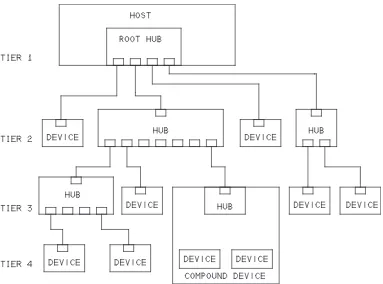
6QRQNQ
I[
The topology, or arrangement of connections, on the bus is a tiered star (Figure 1-1). At the center of each star is a hub, and each connection to the hub is a point on the star. The root hub is in the host. An external hub has one upstream (host-side) connector for communicating with the host and one or more downstream (device-side) connectors or internal connections to embed-ded devices. A typical hub has two, four, or seven ports. When multiple hubs connect in series, you can think of the series as a tier, one above the next. The tiered star describes only the physical connections. In programming, all that matters is the logical connection. Host applications and device firmware don’t need to know or care whether the communication passes through one hub or five.
devices. To increase the available bandwidth for USB devices, many PCs have multiple host controllers, each controlling an independent bus.
$WU
5
RGG
F
%
Q
P
U
KF
G
T
C
V
K
Q
P
U
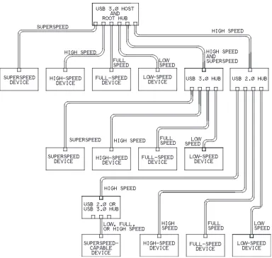
A USB 3.0 host supports all four speeds. A USB 2.0 host supports low, full, and high speed. A USB 1.x host supports low and full speeds only. Exceptions include On-The-Go devices and other special-purpose hosts in embedded sys-tems, which may support only the speeds needed to access specific peripherals. A USB 3.0 hub contains both a USB 2.0 hub and a SuperSpeed hub and han-dles traffic at any speed. SuperSpeed traffic uses the SuperSpeed hub’s circuits and wires, and other traffic uses the USB 2.0 hub’s circuits and wires.
A SuperSpeed-capable device communicates at SuperSpeed only if the host and all hubs between the host and device are USB 3.0 (Figure 1-2). Otherwise the device must use a slower speed. For compatibility with USB 2.0 hosts and hubs,
a SuperSpeed device that doesn’t fully function at a lower speed must at least respond to bus resets and standard requests at another speed to inform the host that the device requires SuperSpeed to perform its function.
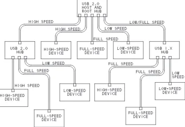
A non-SuperSpeed, high-speed-capable device communicates at high speed if the host and all hubs between are USB 2.0 or higher (Figure 1-3). For compati-bility with USB 1.x hosts and hubs, a high-speed device that doesn’t fully func-tion at full speed must at least respond to bus resets and standard requests at full speed to inform the host that the device requires high speed to perform its func-tion. Many high-speed devices function, if more slowly, at full speed because
adding support for full speed is generally easy and is required to pass USB IF compliance tests.
A device that supports full or low speed communicates with its nearest hub at that speed. For any segments upstream from that hub, if all upstream hubs are USB 2.0 or higher, the device’s traffic travels at high speed.
6
G
T
O
K
P
Q
N
Q
I[
In the world of USB, the words function and device have specific meanings. Also important is the concept of a USB port and how it differs from other ports such as RS-232.
(WPEVKQP
A USB function is a set of one or more related interfaces that expose a capabil-ity. Examples of functions are a mouse, a set of speakers, a data-acquisition unit, or a hub. A single physical device can contain multiple functions. For example,
a device might provide both a printer and a scanner function. A host identifies a device’s functions by requesting a device descriptor and one or more interface descriptors from the device. The descriptors are data structures that contain information about the device.
&GXKEG
A device is a logical or physical entity that performs one or more functions. Hubs and peripherals are devices. The host assigns a unique address to each device on the bus. A compound device contains a hub with one or more perma-nently attached devices. The host treats a compound device in much the same way as if the hub and its functions were separate physical devices. The hub and embedded devices each have a unique address. A USB 3.0 hub is a special case. The hub contains both a USB 2.0 hub function and a USB 3.0 hub function. A composite device has one bus address but multiple, independent interfaces that each provide a function. Each interface can use a different driver on the host. For example, a composite device could have interfaces for mass storage and a keyboard.
2QTV
In general terms, a hardware computer port is an addressable location that can connect to peripheral circuits. A port’s circuits can terminate at a cable connec-tor or be hard-wired to peripheral circuits. For USB, each downstream-facing connector on a hub represents a USB port. Host applications can’t access USB ports directly but instead communicate with drivers assigned to the devices attached to ports. A USB host controller may reside at a series of port addresses the system’s CPU accesses, but these ports are distinct from the ports on the bus.
&
K
X
K
U
K
QP
QH
.CDQT
6JG
*
Q
U
Vŏ
U
&
WV
K
G
U
To communicate with USB devices, a computer needs hardware and software that support the USB host function. The hardware consists of a USB host con-troller and a root hub with one or more USB ports. The software support is typically an operating system that enables device drivers to communicate with lower-level drivers that access the USB hardware.
A typical PC has one or more hardware host controllers that each support mul-tiple ports. The host is in charge of the bus. The host has to know what devices are on the bus and the capabilities of each device. The host must also do its best to ensure that all devices on the bus can send and receive data as needed. A bus may have many devices, each with different requirements, all wanting to trans-fer data at the same time. The host’s job isn’t trivial.
Fortunately, the host-controller hardware and drivers in Windows and other operating systems do much of the work of managing the bus. Each device attached to the host must have an assigned device driver that enables applica-tions to communicate with the device. System-level software components man-age communications between the device driver and the host controller and root hub.
Applications don’t have to know the hardware-specific details of communicat-ing with devices. All the application has to do is send and receive data uscommunicat-ing standard operating-system functions or other software components. Often the application doesn’t have to know or care whether the device uses USB or another interface.
The host performs each of the tasks described below.
&GVGEV&GXKEGU
On power-up, hubs make the host aware of all attached USB devices. In a pro-cess called enumeration, the host determines what bus speed to use, assigns an address, and requests additional information. After power-up, whenever a device is removed or attached, a hub informs the host of the event, and the host enumerates any newly attached device and removes any detached device from its list of devices available to applications.
/CPCIG&CVC(NQY
and gives each transmission a portion of the available time. A USB 3.0 host can simultaneously transmit SuperSpeed data, receive SuperSpeeed data, and trans-mit or receive data at a USB 2.0 speed. A USB 2.0 bus carries data at one speed at a time and in one direction at a time.
During enumeration, a device’s driver requests bandwidth for transfers that must have guaranteed timing. If the bandwidth isn’t available, the driver can request a smaller portion of the bandwidth or wait until the requested band-width is available. Transfers that have no guaranteed timing use the remaining bandwidth and must wait if the bus is busy.
'TTQT%JGEMKPI
When transferring data, the host adds error-checking bits. On receiving data, the device performs calculations on the data and compares the result with received error-checking bits. If the results don’t match, the device doesn’t acknowledge receiving the data and the host knows it should retransmit. In a similar way, the host error-checks data received from devices. USB also supports a transfer type without acknowledgments for use with data such as real-time audio that tolerates errors to enable a constant transfer rate.
If a transmission attempt fails after multiple tries, the host can inform the device’s driver of the problem, and the driver can notify the application so it can take action as needed.
2TQXKFGCPF/CPCIG2QYGT
In addition to data wires, a USB cable has wires for a +5V supply and ground. Some devices draw all of their power from the bus. The host provides power to all devices on power up or attachment and works with the devices to conserve power when possible. A high-power USB 2.0 device can draw up to 500 mA from the bus. A high-power SuperSpeed device can draw up to 900 mA from a USB 3.0 bus. Ports on some battery-powered hosts and hubs support only low-power devices, which are limited to 100 mA (USB 2.0) or 150 mA (Super-Speed). To conserve power when the bus is idle, a host can require devices to enter a low-power state and reduce their use of bus current.
'ZEJCPIG&CVCYKVJ&GXKEGU
or receive data at defined intervals, while in others the host communicates only when an application or other software component requests a transfer.
6JG
&
G
X
K
E
Gŏ
U
&
WV
K
G
U
In many ways, a device’s duties are a mirror image of the host’s. When the host initiates communications, the device must respond. But devices also have duties that are unique. The device-controller hardware typically handles many respon-sibilities. The amount of firmware support varies with the chip architecture. Devices must perform all of the tasks described below.
&GVGEV%QOOWPKECVKQPU&KTGEVGFVQVJG%JKR
Devices must detect communications directed to the device’s address on the bus. The device stores received data in a buffer and returns a status code or sends requested data from a buffer or a status code. In almost all chips, these functions are built into the hardware and require no support in code beyond preparing the buffers to send or receive data. The firmware doesn’t have to take other action or make decisions until the chip has detected a communication intended for the device’s address. SuperSpeed devices have less of a burden in detecting communications because the host routes SuperSpeed communica-tions only to the target device.
4GURQPFVQ5VCPFCTF4GSWGUVU
On power up or when a device attaches to a powered system, a device must respond to standard requests sent by the host computer during enumeration. The host may also send requests any time after enumeration completes.
All devices must respond to these requests, which query the capabilities and sta-tus of the device or request the device to take other action. On receiving a request, the device places data or status information in a buffer to send to the host. For some requests, such as selecting a configuration, the device takes other action in addition to responding to the host computer.
The USB specification defines requests, and a class or vendor may define addi-tional requests. On receiving a request the device doesn’t support, the device responds with a status code.
'TTQT%JGEM
error-check-ing calculations. The device’s response or lack of response tells the host whether to re-transmit. The device also detects the acknowledgement the host returns on receiving data from the device. The device controller’s hardware typically performs these functions.
/CPCIG2QYGT
A device may have its own power supply, obtain power from the bus, or use power from both sources. A host can request a device to enter the low-power Suspend state, which requires the device to draw no more than 2.5 mA of bus current. Some devices support remote wakeup, which can request to exit the Suspend state. USB 3.0 hosts can place individual functions within a USB 3.0 device in the Suspend state. With host support, devices can use additional, less restrictive low-power states to conserve power and extend battery life.
'ZEJCPIG&CVCYKVJVJG*QUV
All of the above tasks support the main job of a device’s USB port, which is to exchange data with the host. For most transfers where the host sends data to the device, the device responds to each transfer attempt by sending a code that indi-cates whether the device accepted the data or was too busy to accept it. For most transfers where the device sends data to the host, the device must respond to each attempt by returning data or a code indicating the device has no data to send. Typically, the hardware responds according to firmware settings and the error-checking result. Some transfers don’t use acknowledgements, and the sender receives no feedback about whether the receiver accepted transmitted data.
Devices send data only when the host requests data. SuperSpeed devices can send a packet that causes the host to request data from the device.
The controller chip’s hardware handles the details of formatting the data for the bus. The formatting includes adding error-checking bits to data to transmit, checking for errors in received data, and sending and receiving the individual bits on the bus.
$W
U
5RGGF
U
C
P
F
&
C
V
C
6J
T
Q
W
I
JRWV
The data throughput, or rate of transfer of application data, between a device and host is less than the bus speed and isn’t always predictable. Some of the transmitted bits identify, synchronize, and error-check the data, and the throughput also varies with the transfer type and how busy the bus is.
For time-sensitive data, USB supports transfer types that have a guaranteed rate or guaranteed maximum latency. Isochronous transfers have a guaranteed rate, where the host can request a specific number of bytes to transfer at defined intervals. The intervals can be as short as 1 ms at full speed or 125 µs at high speed and SuperSpeed. Isochronous transfers have no error correcting, however. Interrupt transfers have error correcting and guaranteed maximum latency. The device specifies a maximum interval, and when a driver has requested a data transfer, the host allows no more than the specified interval, or maximum latency, to elapse between transfer attempts. The requested maximum interval can have a range of 10–255 ms at low speed, 1–255 ms at full speed, and 125 µs to 4.096 s at high speed and SuperSpeed.
Because all devices share the bus, a device has no guarantee that a particular rate or maximum latency will be available on attachment. If the bus is too busy to allow a requested transfer rate or maximum latency, the host refuses to complete the configuration process that enables the host to schedule transfers. The device’s driver can then request a configuration or interface that requires less bandwidth. To take full advantage of reserved bandwidth, the device driver and application software and device firmware must eliminate retries as much as pos-sible. The device should have data ready to send when the host requests it and should be ready to accept data when the host sends it.
Of USB’s four transfer types, the fastest on an otherwise idle bus are bulk trans-fers, with theoretical maximums of around 1.2 MB/s at full speed, 53 MB/s at high speed, and 400 MB/s at SuperSpeed. Isochronous transfers can request the most bandwidth (1.023 MB/s at full speed, 24.576 MB/s at high speed, and 393 MB/s at SuperSpeed). Low speed doesn’t support bulk or isochronous transfers, and the maximum guaranteed bandwidth for a single low-speed trans-fer is 800 bytes per second.
&
GXGN
Q
RK
P
IC
&
GXKEG
%
Q
OR
Q
P
G
P
V
U
A USB device needs the following:
• A device-controller chip with a USB interface and a CPU or other intelli-gent hardware that communicates with the controller. The CPU can be in the same chip as the controller or in a different chip.
• Program code, hardware, or a combination of these to carry out the USB communications in the device.
• Hardware and code to carry out the device’s function (processing data, reading inputs, writing to outputs).
The host that communicates with the device needs the following:
• Host controller hardware and software (typically included with the operat-ing system).
• Device-driver software on the host to enable applications to communicate with the device. The driver may be included with the operating system or provided by the vendor, the chip company, or another source.
• Application software to enable users to access the device. For standard device types such as a mouse, keyboard, or disk drive, you don’t need cus-tom application software, though you may want to write a test application.
6
N
U
H
Q
T
&
G
X
G
N
Q
R
K
P
I
To develop a USB device, you need the following tools:
• An assembler or compiler to create the device firmware (the code that runs inside the device’s controller chip).
• Device-programmer hardware that enables storing the assembled or com-piled code in the controller’s program memory.
• A compiler for writing and debugging host software, which may include a combination of a device driver, filter driver, and application code.
Also recommended are a monitor program for debugging the device firmware and a protocol analyzer for viewing USB traffic.
5VGR
U
K
P
&
G
X
G
N
Q
R
K
P
IC2
T
Q
L
G
E
V
+PKVKCN&GEKUKQPU
Before you can begin programming, you need to select device hardware and a host driver:
1. Specify the device’s requirements. For the USB interface, define the required rate of data transfer and timing or bandwidth requirements. Consider what else your device needs to carry out its function. For example, a data logger might need an analog input. Chapter 3 has more about the capabilities of the different transfer types and how they relate to device requirements.
2. Decide whether the PC can access the device using a driver included with the operating system or a driver you provide. Chapter 7 has more about drivers. 3. Select a device controller chip. Chapter 6 has more about selecting chips.
'PWOGTCVKPI
To enable a host to enumerate your device, do the following:
1. Write or obtain device firmware to respond to standard USB requests from the host and other events on the bus. The requests ask for a series of descriptors, which are data structures that describe the device’s USB capabilities. Chip com-panies generally provide example code that you can modify for a specific appli-cation. A few controllers can enumerate with no device firmware required. 2. For a Windows host, identify or create a device driver and INF (information) file to enable identifying the device and assigning a driver. The INF file is a text file that names the driver the device will use on the host computer. If your device fits a class supported by Windows, you may be able to use an INF file included with Windows. Other operating systems use different methods to match a driver to a device.
3.Build or obtain a development board or other circuit to test the chip and your firmware. Chip companies typically offer development boards for their chips. 4. Load the code into the device and attach the device to the bus. A Windows host will enumerate the device and add it to the Device Manager.