FAKULTET STROJARSTVA I BRODOGRADNJE
PAUL JURIŠIĆ
UTJECAJ STARENJA NA
GRANIČNU ČVRSTOĆU BRODSKOG TRUPA
DOKTORSKI RAD
FACULTY OF MECHAICAL ENGINEERING
AND NAVAL ARCHITECTURE
PAUL JURIŠIĆ
ULTIMATE HULL GIRDER STRENGTH
OF AN AGING SHIP
DOCTORAL THESIS
FAKULTET STROJARSTVA I BRODOGRADNJE
PAUL JURIŠIĆ
UTJECAJ STARENJA NA
GRANIČNU ČVRSTOĆU BRODSKOG TRUPA
DOKTORSKI RAD
Mentor:
Prof. dr. sc. Joško Parunov
FACULTY OF MECHAICAL ENGINEERING
AND NAVAL ARCHITECTURE
PAUL JURIŠIĆ
ULTIMATE HULL GIRDER STRENGTH
OF AN AGING SHIP
DOCTORAL THESIS
Supervisor:
Prof. Joško Parunov, Ph.D.
PODACI ZA BIBLIOGRAFSKU KARTICU
UDK: 629.5.024:629.5.018.4
Ključne riječi: tanker za prijevoz nafte, korozijska istrošenja,
zamorne pukotine, inspekcijski pregledi, ukrepljeni
panel, kolapsna čvrstoća, nelinearna analiza metodom konačnih elemenata, granična čvrstoća
brodskog trupa Znanstveno područje: Tehničke znanosti
Znanstveno polje: Brodogradnja
Institucija u kojoj je rad izrađen: Fakultet strojarstva i brodogradnje
Sveučilišta u Zagrebu
Mentor rada: Dr. sc. Joško Parunov, izvanredni profesor
Broj stranica: 130 Broj slika: 122 Broj tablica: 24 Broj bibliografskih jedinica: 53
Datum obrane: 29. lipnja 2012.
Povjerenstvo: Akademik Ivo Senjanović, prof. emeritus, predsjednik
Dr. sc. Joško Parunov, izv. prof., mentor Dr. sc. Ivan Juraga, redoviti prof.
Dr. sc. Kalman Žiha, redoviti prof.
Dr. sc. Yordan Garbatov, redoviti prof., Instituto
Superior Técnico, Universidade Técnica de Lisboa, Portugal
Institucija u kojoj je rad pohranjen: Fakultet strojarstva i brodogradnje
ZAHVALA
Želim se zahvaliti svom mentoru, prof. dr. Jošku Parunovu, voditelju ovog rada, koji mi je pružio nesebičnu podršku i pomoć oko definiranja zadatka, kao i tijekom izrade ovog
rada. Cijelo me vrijeme vodio i usmjeravao svojim preciznim primjedbama i savjetima.
Dugujem mu stoga neizmjernu zahvalnost i na njegovoj ukupnoj podršci, koju mi je pružio tijekom mog znanstvenog usavršavanja, od samog početka postdiplomskog doktorskog studija na zagrebačkom Fakultetu strojarstva i brodogradnje.
Zahvaljujem se članovima povjerenstva za ocjenu i obranu ovog rada na korisnim sugestijama i komentarima koji su rad učinili boljim.
Želim se posebno zahvaliti gospođi Silvani Škoko Gavranović koja mi je pomogla oko uređivanja teksta, tablica i slika. Hvala također dragim kolegama asistentu Mari Čorku, dipl.ing. i Damiru Rogulju, dipl.ing. na pomoći pri izvođenju složenih proračuna u 3.
poglavlju rada.
Posebno hvala rukovodstvu i svim kolegama Hrvatskog registra brodova, na
odobrenju mog rada, kao i dopuštenju za korištenjem naše baze podataka brodova, te
pruženoj podršci mom stručnom usavršavanju.
Hvala mojoj sestri na pomoći oko prijevoda teksta na engleski jezik, kao i roditeljima
na iskazanom povjerenju u mene. Na kraju veliko hvala mojoj supruzi Adriani, kćeri Paoli i
sinu Fabianu na strpljenju, razumijevanju i odricanjima tijekom proteklih godina.
U Splitu,lipanj 2012. god.
S A D R Ž A J
PREDGOVOR ... v
SAŽETAK ... vi
EXTENDED SUMMARY Ultimate Hull Girder Strength of an Aging Ship ... vii
KLJUČNE RIJEČI ... xx
POPIS OZNAKA I KRATICA ... xxi
POPIS SLIKA ... xxv
POPIS TABLICA ... xxix
1. UVOD ... 1
1.1. Opis problema ... 1
1.2. Hipoteza rada ... 2
1.3. Pregled literature ... 3
1.4. Metodologija istraživanja i struktura doktorskog rada ... 4
2. DUGOROČNO PREDVIĐANJE KOROZIJSKIH ISTROŠENJA BRODSKE KONSTRUKCIJE ... 6
2.1. Propadanje brodske konstrukcije uslijed starenja ... 7
2.2. Općenito o koroziji na brodovima ... 9
2.2.1. Mehanizmi korozijskih procesa ... 9
2.2.2. Pojavni oblici korozije ... 11
2.2.3. Korozija palubne konstrukcije naftnih tankera ... 14
2.3. Metode sprječavanja korozije ... 18
2.4. Pregledi, otkrivanje i mjerenje korozije u brodograđevnoj praksi ... 19
2.5. Vrste pregleda brodskog trupa ... 19
2.5.1. Otkrivanje oštećenja i metode mjerenja ... 21
2.6. Statističko modeliranje korozije ... 22
2.6.1. Modeliranje globalne korozije ... 26
2.6.2. Modeliranje lokalne korozije ... 33
3. ČVRSTOĆA UKREPLJENIH PANELA OSLABLJENIH DJELOVANJEM KOROZIJE I ZAMORNIH PUKOTINA ... 47
3.1. Značajke kolapsa ploča i ukrepljenih panela ... 48
3.1.1. Kolaps neukrepljenih jednoosno opterećenih ploča ... 48
3.1.2. Kolaps ukrepljenih panela palubne konstrukcije ... 49
3.1.3. Metode proračuna kolapsa ukrepljenih panela ... 51
3.1.4. Usporedba metoda ... 65
3.2. Primjena metoda na provjeru nosivosti ukrepljenih panela i ploča sa zamornim pukotinama, te rupičastom korozijom i korozijom u žlijebu zavarenog spoja .... 68
3.2.1. Pukotina ploče ... 69
3.2.2. Pukotina ukrepljenog panela ... 72
3.2.3. Rupičasta korozija ploče (pitting) ... 75
3.2.4. Žljebasta korozija (grooving) ... 78
4. GRANIČNA ČVRSTOĆA KORODIRANE BRODSKE KONSTRUKCIJE... 82
4.1. Kolaps brodskog trupa ... 83
4.2. Proračun graničnog momenta savijanja za slučaj opće (jednolike) korozije brodskog trupa ... 85
4.2.1. Metoda jednog koraka ... 85
4.2.2. Metoda progresivnog kolapsa (PCA) ... 87
4.3. Usporedba rezultata proračuna metode progresivnog kolapsa i metode jednog koraka (program PULS i program MARS) za slučaj opće (jednolike) korozije .. 92
4.4. Granična čvrstoća trupa oslabljenog zamornim pukotinama, rupičastom korozijom i korozijom u žlijebu zavarenog spoja ... 95
5. PRIMJENA REZULTATA ZA UNAPREĐENJE STRATEGIJE INSPEKCIJE, ODRŽAVANJA I POPRAVAKA BRODOVA U SLUŽBI... 99
5.1. Korozijske mape ... 99
5.2. Utjecaj korozijskih istrošenja na kolapsnu čvrstoću ukrepljenih panela ... 102
5.2.1. Jednolika korozijska istrošenja ploča i ukrepljenih panela palube ... 102
5.2.2. Nejednolika korozijska istrošenja (grooving, pitting i pukotine) ploča i ukrepljenih panela palube ... 109
5.3. Provjera granične čvrstoće ... 111
5.3.1. Provjera granične čvrstoće prema pravilima BV-a za jednolika korozijska istrošenja ... 112
5.3.2. Provjera granične čvrstoće prema pravilima BV-a za nejednolika korozijska istrošenja ... 114
5.3.3. Provjera granične čvrstoće prema Usuglašenim Pravilima CSR za tankere s dvostrukom oplatom ... 116
5.4. Primjena korozijskog modela u analizi dinamičke izdržljivosti brodskog trupa ... 118
6. ZAKLJUČAK DOKTORSKOG RADA ... 123
6.1. Zaključna razmatranja i izvorni znanstveni doprinos doktorskog rada ... 123
6.2. Smjernice za daljnja istraživanja ... 124
7. LITERATURA ... 126
ŽIVOTOPIS ... 129
PREDGOVOR
Oštećenja konstrukcije naftnih tankera su relativno učestala unatoč stalnim naporima klasifikacijskih društava i Međunarodne pomorske organizacije (IMO) na povećanju sigurnosti pomorskog transporta. Teške pomorske nesreće u koje spadaju potonuća tankera
imaju za posljedicu gubitke ljudskih života, onečišćenje okoliša i iznimno velike financijske gubitke. Najčešći razlog havarija naftnih tankera je degradacija brodskog trupa i smanjenje
sigurnosti brodske konstrukcije uslijed djelovanja "zuba vremena", u prvom redu kao posljedica korozije i zamornih pukotina. Takva oštećenja smanjuju nosivost konstrukcije i u težim slučajevima mogu dovesti do sloma trupa i gubitka broda, o čemu svjedoče nedavne
havarije tankera "Erica" i "Prestige", koja su donijela izuzetno negativan publicitet
brodogradnji i pomorskom transportu općenito.
Poticaj za izradu ovog rada leži u nastojanju i strateškoj odrednici Hrvatskog registra brodova (HRB) za oplemenjivanjem znanja i unapređenjem spoznaja vezanih za sigurnost
pomorskog transporta. Problematika procjena podobnosti brodskih konstrukcija na isteku
životnog vijeka je svakako jedan od kompleksnijih problema s kojim se susreću klasifikacijska društva u svakodnevnoj praksi. Unatoč regulativi Međunarodne pomorske
organizacije (IMO) koje se potrebno strogo pridržavati, nesumnjivo je da dubinsko i
znanstveno utemeljeno poznavanje problematike sigurnosti brodskih konstrukcija smanjuje
rizik od pogrešne procjene. Za očekivati je da takav pristup doprinese boljoj prepoznatljivosti
HRB-a unutar Međunarodnog udruženja klasifikacijskih društava (IACS). Također je za očekivati poboljšanje interakcije klasifikacijskog društva i brodovlasnika, posebno vezano za procjenu da li brod na isteku životnog vijeka poslati u brodogradilište na izmjenu korozijom oštećene konstrukcije trupa ili je s obzirom na obim potrebnih popravaka za brodovlasnika
isplativije otpisati brod. Također, važna odluka, koja je često vremenski limitirana zbog dokovanja broda, je da li je zamornu pukotinu ili nejednoliko korozijsko oštećenje potrebno
odmah sanirati ili je prihvatljivo popravke odgoditi do sljedećeg periodičnog pregleda broda na suhom. Cilj istraživanja poduzetih u sklopu disertacije je minimiziranje rizika od pogrešne procjene, što se postiže razvojem numeričkih metoda proračuna i njihovom prilagodbom za
SAŽETAK
U radu je provedena analiza korozijskih istrošenja tankera s jednostrukom oplatom na
temelju izmjera debljina elemenata trupa iz baze Hrvatskog registra brodova (HRB) s
periodičnih pregleda brodova u službi nakon 10, 15 i 20 godina. Matematički model koji
opisuje vremensku propagaciju korozije kalibriran je na temelju mjerenja nakon 10 i 15
godina. Predviđanje korozijskih istrošenja na osnovi tako kalibriranog matematičkog modela
vrlo dobro se slaže s izmjerenim korozijskim istrošenjima nakon 20 godina. Istraživanje je
provedeno kako za globalni gubitak momenta otpora glavnog rebra, tako i za lokalna
istrošenja palubne konstrukcije tankera.
Definiran je model jednoosno opterećene ploče i ukrepljenog panela primjenom nelinearne analize metodom konačnih elemenata (NMKE). Model NMKE je provjeren usporedbom s dvije verificirane metode za proračun kolapsa ploča i panela: metodom iz Usuglašenih pravila za projektiranje tankera, te programom PULS klasifikacijskog društva Det Norske Veritas. Na temelju provedene komparativne analize zaključeno je da model
NMKE daje vjerodostojne rezultate pa se primjena modela mogla uzeti u obzir kod daljnjih
analiza čvrstoće panela palubne konstrukcije oslabljene djelovanjem nejednolikih korozijskih
istrošenja i zamornih pukotina. Ovakvi uvjeti, koji odgovaraju realnim uvjetima istrošenja brodskih konstrukcija, mogu se simulirati pomoću NMKE, dok su preostale metode koje propisuju pravila klasifikacijskih društavapogodne samo za jednolika korozijska istrošenja.
Analizirane su dvije metode proračuna granične čvrstoće: metoda jednog koraka uz pomoć programa PULS i metoda progresivnog kolapsa korištenjem programa MARS, klasifikacijskog društva Bureau Veritas. Pokazano je da metoda jednog koraka daje do 2%
niže rezultate proračuna granične čvrstoće u odnosu na metodu progresivnog kolapsa. Predložen je način analize utjecaja nejednolikih korozijskih istrošenja i zamornih pukotina na graničnu čvrstoću trupa inkorporiranjem rezultata kolapsa panela dobivenih NMKE.
U završnom poglavlju rada predložen je niz praktičnih postupaka kao pomoć u proceduri inspekcije i održavanja brodova u službi. Predložene su korozijske mape kojima se vizualno može procijeniti kada će konstrukcijski element trebati zamjenu zbog prekomjernih
korozijskih istrošenja. Predložene su i metode planiranja inspekcijskih pregleda koje kombiniraju degradirajuće učinke napredovanja korozije kroz godine službe s fizikalno utemeljenim proračunskim postupcima određivanja nosivosti oslabljene konstrukcije trupa. Na taj se način međusobno prožimaju metode razvijene u prethodnim poglavljima rada.
EXTENDED SUMMARY
Ultimate Hull Girder Strength of an Aging Ship
Motivation for this thesis lies in the effort and strategic decision of the Croatian Register of Shipping (CRS) for improving knowledge related to the safety of maritime transport. The issue of ship structural assessment at the end of design service life is one of the most complex and important problems faced by the Classification Societies. The scientifically based knowledge of structural behaviour of aged ship may reduce the risk of wrong decisions. Such risk is always present, despite the existing regulations of the International Maritime Organization (IMO).
One of the most important questions imposed to the Classification Societies is to define whether the ship at the end of design service life should be repaired or to be sent to scrap and with that will be taken out of service. Also, another critical decision has to be taken, whether fatigue cracks and non-uniform corrosion degradation should be repaired immediately or it is acceptable to postpone repairs until the next ship periodic survey. This is a time-constrained decision because of the short dry docking period. Both of questions are related to large economic cost from one side and shipping safety and reputation of the Classification Societies from the other side. Development of a new approach dealing with the ultimate hull girder strength analysis of aging ships, adapted for the use in engineering practice, will contribute to the rational decision for maintenance planning, inspection and repair of aging ship.
It is expected that the approach, developed in this thesis, will contribute to a better positioning of the CRS within the International Association of Classification Societies (IACS). It is also expected to improve the interaction between the Classification Societies and ship-owners.
1. INTRODUCTION
The corrosion makes ships prone to structural degradation and the possibility of accidents increases with the aging of ships. Statistical analyses reveal that corrosion degradation is the number one cause for structural casualties in aged ships. The consequences of corrosion wastage can be very serious leading to crack initiation and propagation to such extent to cause the loss of ship.
Hull girder section modulus (HGSM) is a fundamental descriptor of the ship longitudinal strength and can be used to measure how the ship hull deteriorates over time because of corrosion. Traditional strength analysis uses simplified deterministic approaches to account for this time dependent deterioration process. Common practice is that nominal corrosion additions are to be predefined. Thus, the Classification Societies Rules, including the newly developed Common Structural Rules (CSR) for Double-hull Oil Tankers [1], assume constant loss of HGSM during the whole service lifetime of a ship. Ship structural assessment, in the design phase, is performed assuming such "net" HGSM. Although "the Rules" approach is practical, it is obviously conservative one, as HGSM loss is actually a time-dependent non-linear function. Nowadays, there is a clear trend of adopting non-linear models in order to predict the long-term corrosion wastage degradation and the associated HGSM reduction as a function of time. Developing a direct approach accounting for the real corrosion degradation will be a very important and useful tool for the Classification Societies and ship owners in order to predict the long-term hull degradation and to decide whether the renewal of hull structures are necessary and when would be the optimal time for repairs.
The time for repair of aged ships is empirically determined by the Classification Societies, based on existing criteria of damage allowance. One of the most important criteria is the so-called "10% rule", which represents tolerated 10% loss from initial as-built HGSM.
Recently, based on numerous studies and public pressure as well, the approach for longitudinal strength assessment through HGSM of new-built ships started to be complemented based on the hull girder ultimate strength (HGUS) assessment, as a physically justified criterion for entire capacity of the ship hull. The logical continuation of this approach in further research is that for the old ships HGUS is used as a criterion of structural adequacy. The results of such approach were used in this thesis.
Although the longitudinal strength of the hull structure is in focus as the most important component of the ship strength, the results and findings presented in this thesis can be used in the calculations of other components of strength, primarily in the analyses of the primary transversal structure using the finite elements method (FEM).
2. ASSESSMENT OF HGSM LOSS AND THE LOCAL CORROSION WASTAGE One of the principal studies in this thesis is to analyse the practical applicability of the currently used long-term non-linear corrosion wastage models and their predictions. The corrosion degradation of three tanker ships after 20 years in service have been analysed based on the real thickness measurements at 10 and 15 years in service. The actual measurements
after 20 years' service life were then compared to the theoretical model predictions and statistical measures of uncertainty were determined. The assessment of HGSM reduction was performed, followed by the assessment of local corrosion deterioration of main deck plates and longitudinals. For the local corrosion deterioration analysis, total number of 6567 measurements was used. The approach applied here is different comparing to other similar studies, as individual ships are considered, while in other similar studies whole fleets of ships are analysed together. The main goal of the present approach is to fit non-linear corrosion deterioration models to measured corrosion thickness for 10 and 15 years of service life, and then to assess how well the corrosion deterioration after 20 years is predicted.
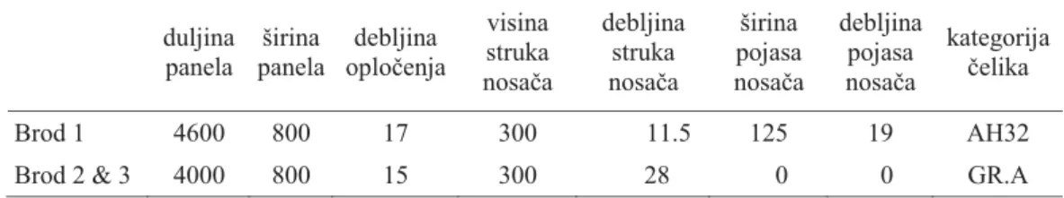
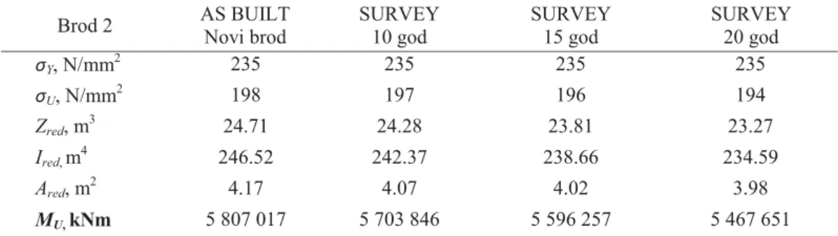
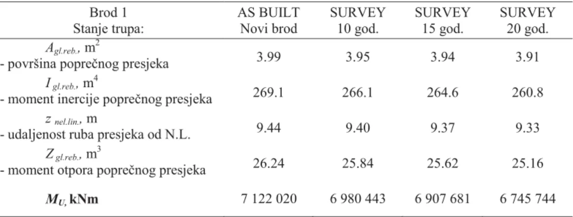
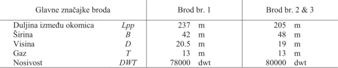
First, this thesis analysis the corrosion wastage of three oil tankers with single-hull structure built in the eighties. The whole cargo area is made of mild steel for the two sister ships, while the third one has high tensile steel in the bottom and deck areas and mild steel in the neutral axis area including the longitudinal bulkheads. Central tanks along the cargo hold areas are cargo oil tanks, while wing tanks are used for ballast or cargo. The main characteristics of the three single-hull tankers are shown in Table 2.2, and the midship section of the first single-hull oil tanker is shown in Figure 2.11. HGSMs in cargo hold area were calculated using MARS, the program for 2D sectional analysis developed by the classification society Bureau Veritas (BV).
The HGSM reduction was defined based on the following procedure. First, the as-built HGSM is calculated. Then, thickness of the structural elements (plates and longitudinals) contributing to the longitudinal strength is modified according to the results of thickness measurements from the Croatian Register of Shipping (CRS) file. Gauging records were obtained during the periodic dry-dockings and close-up surveys of ships in service after 10, 15 and 20 years. Corrosion deterioration models of the ships were determined for the transverse sections considering the central tanks as cargo oil tanks and the wing tanks as ballast tanks.
The aging effect was measured by the HGSM loss R(t), which represents the ratio of as-gauged HGSM and as-built HGSM, as given by eq. (2.7).
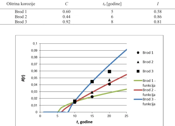
Results for the measured R(t) for the three ships after 10, 15 and 20 years are presented in Table 2.3. HGSM loss is determined as a function of time taking into account the coating lifetime. The equation (2.8) is used to define the HGSM loss as a function of time has been proposed by Wang et al. [9]. The governing parameters of Eq. (2.8), C and index I are defined based on the regression analysis using a data set of real measurements of corrosion
depth that leads to the HGSM loss. The coating life, t0, which represents the time when
HGSM starts to degrade from the as-built condition is assumed.
In order to analyse the accuracy of the HGSM prediction model, Eq. (2.8) is fitted through the calculated points of the HGSM loss at 10 and 15 years. The governing parameters of Eq. (2.8) are presented in Table 2.5, while the corresponding diagrams are shown in Figure 2.14.
It can be seen from Figure 2.14 that the HGSM loss at the 20th year for ship no. 1 is significantly underestimated by the model prediction. The prediction of the HGSM loss at the 20th year for ship no. 2 is satisfactory. The HGSM reduction is almost linear from the time of the coating breakdown at 6th year. The results for ship no. 3 indicate that the coating lifetime is the longest, resulting in 8 years, but after the breakdown of the coating, the corrosion deterioration is very fast. The prediction of the HGSM reduction for that ship overestimates the actual HGSM loss at 20th year.
It should be mentioned that there is a large uncertainty associated to the HGSM loss as the corrosion degradation is different for each transverse section of the ship hull. It is assumed that the measured corrosion depths of the sections are representative (average) of the corrosion losses. Additional analyses are required to reduce the uncertainty of the long-term predictions of corrosion reduction of HGSM.
The local corrosion wastage analysis is performed separately for plates and longitudinals of the main deck in ballast and cargo tanks. For the local corrosion wastage, equation (2.9) is proposed according to Gua et al. 2008 [10].
In equation (2.9) [10] C(t) is the corrosion wastage at age t; t0 is the year when thickness of the plates starts to deviate from the as-built condition; D and E are constants that can be determined according to the measurement data.
The total number of measurements of deck plates and longitudinals (stiffeners) used in the thesis are 6567. 2135 measurements were used for ship no. 1, 2079 for ship no. 2, and 2353 for ship no. 3 respectively. Similarly to the prediction model of HGSM loss, curves are fitted through the real measurements of corrosion depth for deck plates and longitudinals at 10th and 15th years. Since there are three unknown variables in equation (2.9) (t0, D and E),
and only two calibration points (at 10 and 15 years) are available, t0 has to be assumed.
Eq. (2.9) is fitted to the mean value of corrosion depth and also to the value of the 95% confidence level of the corrosion depth, which is related to so-called the extreme corrosion depth. To estimate the extreme corrosion depth, the probability density function of corrosion depth is fitted to the each data set. The Weibull probability density function is
assumed to be the most adequate for representing the corrosion depth at any time during the ship service life (Parunov et al. 2007 [13], Gua et al. 2008 [10]). Such satisfactory fitting of the Weibull probability density function is confirmed also in the present study, as demonstrated in Figure 2.15 and Figure 2.16, for deck plates in cargo tanks at year 15th and 20th for ship no. 2.
The mean value and the extreme corrosion depth of the main deck plates in cargo tanks are presented in Figures 2.17 and 2.18 respectively. It can be seen from Figure 2.17 that the newly developed corrosion model over-predicts the mean value of corrosion depth of ship no. 2 while it underestimates the measured corrosion depth for ship 1 and 3. Coating life is estimated to be 6.5 years.
It is evident, as can be seen from Figure 2.18, that the extreme corrosion depth after 20th year is well estimated for ship no. 3. For ship 1 and 2, the corrosion depth after 20th year is underestimated and overestimated respectively. The corrosion depth trend is almost linear for ship 2 and 3, while the coating life is estimated to 5 years for all three ships.
It is interesting to notice from Figures 2.17 and 2.18 that for ship no. 2, the corrosion depth after 20th year is only slightly higher compared to the corrosion depth after 15th year. For ship no. 1, in contrary, the difference between the corrosion depth at 20th and 15th years is unexpectedly large, indicating that in this case the concave curve is more appropriate for corrosion process modelling, as it is shown in Figure 2.7 for type A curve (Paik [18]).
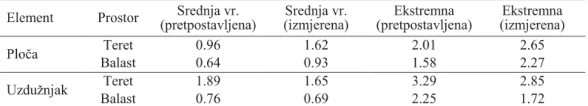
The mean and extreme values of corrosion depth of main deck longitudinals in cargo tanks are presented in Figures 2.19 and 2.20 respectively. All three estimations overestimate the real corrosion depth measurements after 20th year. That is true for both mean and extreme corrosion depth values. It has been noticed that for deck plates, the corrosion rate is reduced between years 15 and 20 for ship no. 2, which is also confirmed for deck longitudinals. Based on the analysis just presented, one may conclude that the corrosion depth of deck longitudinals is larger comparing to deck plates. Thus, for a 20 years' service life, the extreme value of corrosion depth of deck longitudinals is between 3 and 4 mm, while for deck plates it is between 2 and 3 mm. Coating life of deck longitudinals is estimated to be 8 and 5 years for the mean and extreme value of corrosion depth respectively.
The mean and extreme values of the corrosion depth for main deck plates in ballast tanks are presented in Figures 2.21 and 2.22 respectively. For ship no. 1, similar to cargo tank deck plates, the difference between the corrosion depth at 15th and 20th year is quite large, indicating that the type of concave curve should be used for the corrosion model. The tendency of the reduced corrosion rate for the period between 15th and 20th years, which has
been already noticed for the cargo tanks, is evident also for ballast tanks of ship no. 2. Consequently, the corrosion depth after 20 years is systematically overestimated by theoretical prediction for that vessel. For ship no. 3, predicted corrosion depth agrees well with the real measurements for both mean and extreme values of corrosion depth.
By comparing Figures 2.21 and 2.22 with Figures 2.17 and 2.18, it appears that the corrosion depth is higher for deck plates in cargo tanks than in ballast tanks. The coating life is estimated to be the same as for the deck plates in cargo tanks, i.e. 6.5 and 5 years for the mean and extreme values of the corrosion depth respectively.
The mean and extreme values of the corrosion depth of main deck longitudinals in ballast tanks are presented in Figures 2.22 and 2.23 respectively. The estimation for the mean value slightly overestimates the real measurements of corrosion depth after 20th year. For the extreme value prediction, the developed model overestimates the real measurements for ships 1 and 2, while it underestimates the measured corrosion depth for ship no. 3. Generally, measured corrosion depth for deck longitudinals in ballast tanks is approximately the same as for deck plating in ballast tanks. The coating life for deck longitudinals in ballast tanks reads 5 years for the extreme corrosion depth, while between 6.5 and 8 years for the mean corrosion depth wastage.
In order to quantify uncertainty of the new developed corrosion degradation model used in the present study, the predicted and measured mean and extreme corrosion depth values (presented in Tables 2.7-2.9) were subjected to further statistical analysis.
The average ratios of the measured and predicted corrosion depth read 1.01 and 0.96 for the mean end extreme corrosion depth respectively, while the corresponding standard deviations read 0.30 and 0.24. This indicates that the new developed model has almost no bias, but uncertainty of predictions is rather large. If only cargo tanks are considered, then the average ratios of the measured/predicted corrosion depth read 1.01 and 0.92 for the mean end extreme corrosion depth values respectively, while the corresponding standard deviations read 0.38 and 0.23. If only ballast tanks are considered, then, the average ratios measured/predicted corrosion depth read 1.01 and 1.00 for the mean and extreme corrosion values respectively, while the corresponding standard deviations read 0.22 and 0.26. Therefore, it is concluded that the agreement between the predicted and measured corrosion depths is better for the ballast tank structural components than for the cargo tanks.
One of the principal objectives of this thesis is to fit the existing non-linear corrosion depth models to the corrosion measurements at 10th and 15th year and then to compare it with
the measurements at 20th year, aiming to investigate the uncertainty of the long-term corrosion depth prediction. The following conclusions are drawn:
1. The estimation of the ship hull girder section modulus loss after 20th year is satisfactory for 2 out of the 3 studied ships. Coating life is between 5 and 8.5 years.
2. The corrosion depth in cargo tanks is larger than the one in ballast tanks, while deck longitudinals in cargo tanks experienced the largest corrosion wastage of all structural elements analysed.
3. The non-linear long-term local corrosion depth model based on the measurements after the 10th and 15th year in average predicts very well the corrosion depth after the 20th year. However, the uncertainty of that prediction, measured by standard deviation, is rather large.
4. There is no correlation between the corrosion severities of a local deck plates (longitudinals) and that of HGSM loss based on the corrosion models analyses. Deck plate can be severely wasted while the overall wastage of the entire hull section may remain at a very low level. Therefore, corrosion wastage of local plate and HGSM loss are to be treated independently.
5. Also, it was found that the new developed model is more accurate and reliable in ballast than in cargo tanks.
3. COLLAPSE STRENGTH OF PLATES AND STIFFENED PANEL SUBJECTED TO CORROSION AND FATIGUE CRACKS
A model for collapse assessment of uniaxially compressed plates and stiffened panels has been developed and tested employing the non-linear finite element method (NLFEM) using commercial software FEMAP with NX Nastran. The objective was to define a model that is simple enough to be applicable in every-day engineering practice. The principal difficulties are related to the choice of an appropriate definition of the model extent and boundary conditions, especially the mathematical description of the initial imperfections that have dominant influence on final collapse strength.
The model for unstiffened plates is extended between the longitudinals along longitudinal plate edges and between the transverse web frames along transverse plate edges as has been shown in Figure 3.9. The typical element (mesh) size employed is 50 × 50 mm. This corresponds to about 16 elements in the shorter (transverse) direction and to about 80 elements in the longer (longitudinal) direction for an unstiffened plate of large oil tankers.
The boundary condition can affect significantly the plate strength. One bay plate model is used in this thesis, where the plate is simply supported at longitudinal edges and clamped at the transverse ones. This one bay model may be appropriate for uniaxially loaded rectangular plates.
The extent of the model used for stiffened panel is one half of stiffener spacing on each side of the longitudinal in transverse direction and half of web frame spacing on each side of web frame in the longitudinal direction, as shown in Figure 3.10. For the present NLFEA the following boundary conditions are applied where T [x, y, z] indicates translational constraints, and R [x, y, z] indicates rotational constraints; "0" indicates constraints, and "1" indicates no constraints as is presented in Figures 3.13 and 3.14; Symmetric condition at A-A0: R [1,0,0] with all plate nodes and stiffener nodes having an equal x - displacement; Symmetric conditions at B-B0: T [0, 1, 1] and R [1, 0, 0]; Symmetric conditions at B-B0: T [0, 1, 1] and R [1, 0, 0]; Symmetric conditions at A-B and A0-B0: T [1, 0, 1] and R [0, 1, 1]; At transverse floors: T [1, 1, 0] for plate nodes, and T [1, 1, 0] for stiffener web nodes.
Welded metal structures during fabrications always have initial imperfections in the form of initial deformations and residual stresses [38]. The residual stress effect was excluded from the analysis in this thesis. Initial imperfections in elastic buckling mode with suitable magnitudes were chosen in the NLFEM analyses. The plate initial deformation magnitude is calculated by equations 3.3 and 3.4 and the result is presented in Figure 3.15. The shape of the initial deformation is obtained by linear elastic buckling analysis.
For stiffened panels, three types of initial deformation are considered [37]: plate initial deflection, beam-column initial deflection, and sideways initial deflection of stiffener web. Shapes of the initial deformations are assumed to be similar to the stiffened plate buckling modes (equations 3.5 – 3.7). Total initial imperfections of the models are shown in Figures 3.16, 3.17 and 3.18.
The model was tested by comparing NLFEM with two widely recognized methods for calculating the collapse (ultimate compressive strength) of unstiffened plates and stiffened panels. The first one is a simplified formula of harmonized rules for the construction of oil tankers with double hulls (CSR), and the second one is the PULS program of the Classification Society DNV.
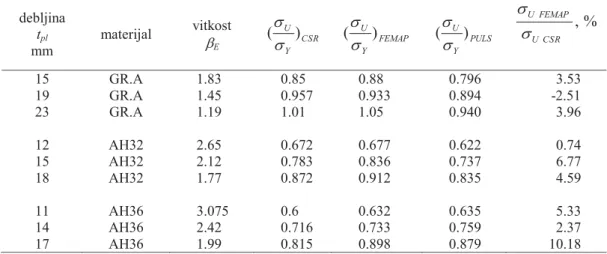
First, nine unstiffened plates made from three different types of materials were analysed and for each material three different thicknesses were chosen, as shown in Table 3.1 [38]. The plate slenderness, EE, was between 1.19 and 3.075, which represents a range of slenderness that usually occurs in practice. The panel dimensions were
4300 × 815 mm. Table 3.1 shows the results of ultimate strength obtained by NLFEM, program PULS, and Frankland's formula (CSR). The comparison between the results obtained by these three methods shows that a good match was achieved. Mean value of discrepancy of NLFEM compared to CSR is 3.9%, while the standard deviation reads 3.6%. The maximal discrepancy reads about 10%. This confirms the reliability of the used finite element model (NLFEM), as shown in Figure 3.23.
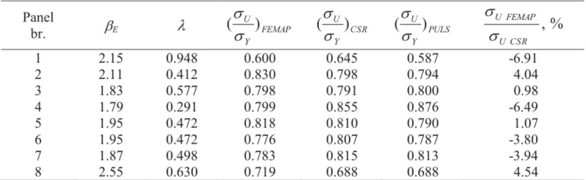
Then, eight stiffened panels were analysed by NLFEM using the program Femap with NX Nastran. Three types of stiffeners were considered: flat profiles, L-profiles, and T-profiles. Geometrical characteristics of the stiffened panels, in millimetres, and the results of NLFEM to assess the ultimate strength are shown in Table 3.2. The ultimate strength σU for eight stiffened panels were in the range from 0.60 σY to 0.83 σY.
The comparison of the results obtained using NLFEM, program PULS and the formula from CSR, for the above-mentioned eight stiffened panels is presented in Table 3.3. There is a very good agreement of results obtained by the different methods. Mean value of the model uncertainty of NLFEM compared to CSR is -0.33%, while the standard deviation reads 4.52%. The largest difference between the results obtained using NLFEM and CSR reads about 7%, which is satisfactory. It is interesting to notice that the maximal difference between the two rule methods, PULS and CSR, is larger than the maximal discrepancy between proposed NLFEM and CSR. That is another favourable indicator of appropriateness of the NLFEM model proposed in the thesis.
To conclude, it was shown that the proposed NLFEM model is effective, applicable, and that it can be used in practice for an evaluation of non-corroded, and uniformly corroded plates and stiffened panels. Advantages of NLFEM model in comparison with the analytical formulas of CSR rules and program PULSE is its ability to change a number of parameters and load conditions that occur during ship's service life. The cracks of plates, cracks of stiffened panels, corrosion in weld joints (grooving), and pitting corrosion often appear in the structure after several years of ship in service. These conditions can be simulated using NLFEM, and then analysed, which for the other two methods is not the case.
Figures 3.26 to 3.47 present some of these phenomena and their effect on the strength of the panel deck structure. Differences in "load–end shortening curves” as a result of non -uniform corrosion and cracks are presented in figs. 3.31, 3.36, 3.41 and 3.47.
Definition of the simple structural model that is applicable in every-day engineering
practice, its boundary conditions and initial deformations as well as verification of such model represents a contribution of the present thesis. Furthermore, there are no references in
the available literature describing the application of the FE software Femap with NX Nastran in collapse strength assessment of plates and stiffened panels.
4. HULL GIRDER ULTIMATE STRENGTH OF CORRODED SHIP STRUCTURE In this thesis, two methods for the assessment of the ultimate longitudinal capacity of hull structure are used. Both methods are in accordance with the requirements of CSR: the one-step method where PULS is used and the progressive collapse method using program MARS. The HGUS of three oil tankers is studied. The analysis is performed firstly for the initial as-built HGSM and then for reduced HGSM subjected to uniform corrosion, measured at 10th, 15th and 20th year of service. It was shown (Tables 4.7, 4.8 and 4.9 as well as in Figures 4.7, 4.8 and 4.9) that considering uniform corrosion wastage, the one-step method gives a 2% lower ultimate strength in comparison to the method of progressive collapse. The reason for this is that the method of progressive collapse gradually (in steps) calculates the limit of HGUS. It is assumed that once HGUS of individual deck stiffened panel is reached, loaded panel can still carry some load, before it comes to the point of the hull structure collapse. While the one-step method calculates HGUS from one step assuming that the collapse of the hull occurs as soon as bending moment reaches the limit value of the deck panels' strength.
Also, based on the comparison of the effect of general (uniform) corrosion for all three models (ship 1, ship 2, ship 3), it can be concluded that after the hull surveys at 10, 15 and 20 years there was not any reduction in the longitudinal strength of more than 10%, that is acceptable reduction in accordance with the IMO requirements. In all three ships this 10% reduction could happen between 25 to 30 years, i.e. later than designed ship lifetime. The achieved results of collapse strength of plates and stiffened panels, described in chapter 3 of the thesis, are incorporated in the calculation of HGUS. The results presented in Figures 4.10 to 4.13 confirmed that the degradation effects, such as uneven corrosion wastages (grooving and pitting) and cracks, could significantly reduce the ultimate strength of hull structure.
Research is performed within the present work in order to find appropriate way to incorporate aging effects in HGUS calculation. For the case of non-uniform corrosion and
fatigue cracks it is proposed to combine the methods for HGUS with NLFEM of single deck
5. STRATEGIES FOR SURVEY, MAINTENANCE AND REPAIR IMPROVEMENT OF AGING SHIPS IN SERVICE
In the last chapter of this thesis several practical approaches are proposed to assist the process of survey and maintenance of ships in service. First, the method for predicting the corrosion degradation can be presented in the form of corrosion maps, allowing surveyors to facilitate the practice of making costly repairs and detailed examinationof the hull structure, as presented in Figures 5.1 to 5.4. The allowable thickness reduction for deck structures of oil tankers reads 4 mm, with the reference to CSR. This value is the margin of the comparison considering actual corrosion wastages. In a current research project within the IACS harmonization project team on CSR corrosion addition, a value of 4 mm is also considered as acceptable [12].
Then the increase of deck stress due to the loss of HGSM was analysed and at the same time the reduction of the collapse strength of deck structure due to the negative effects of corrosion was determined. This simple method (see Figures from 5.5 to 5.16) shows the point in time when it is expected that the applied stress will exceed the strength of stiffened panels of the main deck. Classifications societies then suggest replacement of the corroded plating with a new one in order to avoid an unsafe zone for the aging ships. This approach is for the first time proposed by Gua et al. [10] for unstiffened deck plates, while it is extended in the present thesis to the stiffened panels including the effect of uneven corrosion (grooving
and pitting) and cracks (presented in Figures 5.17 to 5.20). These calculations are based on
methods and results developed in the 3. chapter of this thesis.
The vertical bending moment, as one of the most important criteria for longitudinal strength, must be controlled during the ship's service. However, such calculations are subjected to uncertainty regarding the unpredictability of the corrosion processes and wave loads. To account for uncertainties, the classification societies use partial safety factors. These factors are determined using probabilistic methods and practical experience from the past and their values can vary significantly. To demonstrate these large differences, in this thesis two "sets" of partial safety factors were used according to the rules of BV and CSR. Comparing the results, it was observed that in all three ships and their respective hull conditions (after 10, 15 and 20 years) HGUS is in accordance with the requirements of BV rules for the uniform corrosion, while the CSR results are considerably worse (presented in Figures 5.20 to 5.30). In calculation of HGUS, results obtained in the 4. chapter of the thesis are employed.
Finally, an improved method for estimating the fatigue strength of deck structure of oil tanker is shown. The employed fatigue calculation is similar to the CSR method. The main
difference from the CSR approach, where the constant wastage is used from the beginning to the end of the ship's life, is that the realistic corrosion degradation mode, developed in the 2.
chapter, was used in the present study. The accumulated damage is calculated for each year of
service individually, taking into account the actual stress of HG, determined based on the measured HGSM loss. The results of these calculations, for three ships, are shown in Figure 5.31, and Tables 5.1-5.3. The tables also show the results for a constant HGSM loss over the entire lifetime according to the fatigue requirements from CSR rules (25% of the maximum corrosion of particular hull elements) and also for longitudinal strength requirements (50% of the maximum corrosion of particular elements). The a.m. tables show that the calculated lifetime according to the measured corrosion wastage may give better insight into the hull girder fatigue behavior compared to the rule approach.
6. CONCLUSION AND GUIDELINES FOR FURTHER RESEARCH
The researches which are described in this thesis are aimed to improve the application of direct calculations in the planning of survey and repairs of ship's structure. Further research in this area can be recommended within two fields:
x Development and practical implementation of crack propagation methods to the ship's structure;
x Development and application of reliability and risk-based methods for maintenance of ship structures.
Crack propagation methods based on fracture mechanics are currently being developed Benefit of using these methods is that small fatigue cracks that appear around the welds can be tolerated and analysed. The crack propagation methods have still not found appropriate place in the shipbuilding industry because of the inherent complexity of welded ship structures. Consequently, there are a number of uncertainties related to the determination of their load and capacity and also regarding the variability of the effects of corrosion. Especially important are the effects of various parameters that can affect determination of the stress intensity factor. A typical example is the uncertainty in calculation of the stress concentration factors in presence of the cracks. Regarding fatigue load of ship structures, the greatest difficulty is the unpredictability of random wave loading, which is a major factor in fatigue loading and crack propagation. The prediction of crack growth under conditions of random loading is a challenging and complex problem that is currently the subject of research. Improvement of the methods for the analysis of the crack propagation could have an extremely positive impact on the effectiveness of the method developed in this thesis.
Considering various uncertainties related to the determination of corrosion wastage, load, strength and fatigue resistance of ship structures, the application of reliability-based methods could be the appropriate methodology for these calculations. It is important to mention that the structural reliability methods could be applied not only to determine the safety index (or the probability of structural damage), but also for the sensitivity analysis with respect to relevant variables. In other words, the reliability-based methods can be used to determine which parameters strongly affect the fatigue damage, and surveyors in practice could pay more attention to them. In the future, research in this area could be recommended with a special consideration on the practical applicability of the reliability- and risk-based methods for planning inspection intervals and repairs.
KLJUČNE RIJEČI
- tanker za prijevoz nafte - korozijska istrošenja
- zamorne pukotine - inspekcijski pregledi - ukrepljeni panel - kolapsna čvrstoća
- nelinearna analiza metodom konačnih elemenata
- granična čvrstoća brodskog trupa
KEY WORDS
- oil tanker
- corrosion wastage - fatigue cracks - hull structure survey - stiffened panel
- collapse compressive strength - non-linear finite element method - hull girder ultimate strength
POPIS OZNAKA I KRATICA
a - duljina ploče
Aeff - efektivna površina nakon izvijanja ukrepljenog panela palube
Agl.reb - površina poprečnog presjeka brodskog trupa
b - širina ploče
B - širina broda
C (t) - učinak starenja (lokalno korozijsko istrošenje u vremenu t)
C - konstanta jednadžbe R(t)
C1, C2 - koeficijenti koji uzimaju u obzir značajke korozijskog procesa
dS - sredina razreda izmjerenih podataka korozijskih istrošenja
D - visina broda
DWT - nosivost broda
E - modul elastičnosti čelika
f0 - faktor koji uzima u obzir neoperativno vrijeme broda
f (dS) - funkcija gustoće vjerojatnosti
F (dS) - funkcija razdiobe vjerojatnosti
hf - širina prirubnice uzdužnjaka
hw - visina struka uzdužnjaka
HGSM - moment otpora glavnog rebra
I - konstanta jednadžbe R(t)
Igl.reb. - moment inercije poprečnog presjeka brodskog trupa
Ired - reducirani moment tromosti poprečnog presjeka K2 - koeficijent S-N krivulje za F-detalj
{K} - matrica krutosti
Lpp - duljina broda između okomica
m - oblik izvijanja neukrepljene ploče
MRi - raspon momenata savijanja
MU - granični moment savijanja brodskog trupa
Mwvhog -vertikalni moment savijanja u pregibu
Mwvsag - vertikalni moment savijanja u progibu
NL - broj ciklusa u očekivanom vijeku broda
N(ds) - broj izmjerenih podataka o smanjenju debljine palubnih opločenja i
R (t) - učinak starenja (gubitak momenta otpora glavnog rebra u vremenu t)
R2 - koeficijent determinacije
{R} - vektor opterećenja
Sq - raspon naprezanja na presjeku dva strukturna elementa SRi - raspon naprezanja
SSer - suma kvadrata reziduuma
SStot - ukupna suma kvadratnih odstupanja izmjerenih vrijednosti xi od srednje izmjerene vrijednosti x
t - vrijeme
t0 - godina u kojoj HGSM gubitak počinje odstupati od stanja novog
broda (vijek trajanja zaštitnog premaza) tf - debljina pojasne trake uzdužnjaka
tpl - debljina ploče
tr - debljina korozijskog gubitka
tw - debljina struka uzdužnjaka
T - životni vijek konstrukcije
Tc - vrijeme trajanja zaštitnog premaza
{U} - vektor pomaka
woc - maksimalna veličina gredno-štapne inicijalne deformacije
wopl - maksimalna vrijednost inicijalne deformacije ploče
wos - najveća vrijednost bočne inicijalne deformacije struka uzdužnjaka
x - srednja vrijednost
xi - izmjerene vrijednosti korozijskog istrošenja
yi - predviđene vrijednosti korozijskog istrošenja
zdk-mean - vertikalna udaljenost između srednje visine palube i dna broda
znel.lin. - udaljenost ruba presjeka od neutralne linije
zNA-mean - vertikalna udaljenost između neutralne osi reduciranog poprečnog
presjeka
zT - udaljenost neutralne linije od osnovice
Zgl.reb. - moment otpora poprečnog presjeka brodskog trupa
Zred - reducirani moment otpora palube
α' - konstanta jednadžbe C(t) koja se može odrediti prema izmjerenim podacima o korozijskim istrošenjima
αi - proporcija stanja broda teret/balast tijekom života
β - konstanta koja se može odrediti prema izmjerenim podacima o
korozijskim istrošenjima
βE - koeficijent vitkosti ploče
γm - parcijalni faktor sigurnosti prema pravilima BV za materijal
γR - parcijalni faktor sigurnosti prema pravilima CSR za materijal i geometrijsku nesigurnost
γR1 - parcijalni faktor sigurnosti prema pravilima BV za izdržljivost
γS - parcijalni faktor sigurnosti prema pravilima CSR za mirnu vodu
γS 1 - parcijalni faktor sigurnosti prema pravilima BV za mirnu vodu
γW - parcijalni faktor sigurnosti prema pravilima CSR za valove
γW 1 - parcijalni faktor sigurnosti prema pravilima BV za valove
Γ( ) - gamma funkcija
ε - deformacija
εU - granična deformacija
4 - parametar skaliranja funkcije gustoće vjerojatnosti
N - zakrivljenost poprečnog presjeka brodskog trupa
λ - koeficijent vitkosti uzdužnjaka sa sunosivom širinom
ν - Poissonov koeficijent
ξ - parametar oblika Weibullove razdiobe
σU - granična čvrstoća
σY - granica tečenja
υi - argument nekompletne gamma funkcije
ABS - American Bureau of Shipping
BV - Bureau Veritas
CSR - Common Structural Rules DnV - Det Norske Veritas
ESP - Enhanced survey programme
FEMAP/NX Nastran - Računalni program za provjeru čvrstoće metodom konačnih
HGSM - Hull girder section modulus HGUS - Hull girder ultimate strength
HRB/CSR - Hrvatski registar brodova (Croatian Register of Shipping) IACS - International association of classification societies IMO - International Maritime Organization
ISSC - Međunarodni kongres za brodske i pomorske konstrukcije IUMI - International Union of Marine Insurance
MARS - Računalni program za provjeru geometrijskih karakteristika poprečnog presjeka i granične čvrstoće brodskog trupa BV-a NMKE/NLFEM - Nelinearna metoda konačnih elemenata/ Non-linear finite element
method
PSC - Nadzor državnih luka
PULS - Računalni program za provjeru kolapsne čvrstoće ploča i
ukrepljenih panela polu-analitičkom metodom DnV-a (Panel Ultimate Limit State)
POPIS SLIKA
Slika 1.1 - Statistički podaci mjerenja debljina strukturnih elemenata glavne palube
naftnih tankera [12]. ... 3 Slika 2.1 - Grupirani razlozi ukupnih gubitaka za sve tipove brodova veće od 500
BRT (Izvor: International Union of Marine Insurance IUMI, [5]) ... 7 Slika 2.2 - Ukupni gubici tankera i brodova za rasuti teret većih od 500 GT (Izvor:
International Union of Marine Insurance IUMI, [5]) ... 8 Slika 2.3 - Mehanizam opće korozije na unutarnjoj strani palubnog lima tankera za
naftu [6] ... 12 Slika 2.4 - Mehanizam djelovanja korozije "pittinga" na palubnim limovima u
području tankova tereta (nafte) [6]... 13 Slika 2.5 - Naneseni zaštitni premaz (epoksi tip) u tankovima balasta naftnog
tankera [31] ... 19 Slika 2.6 - Otkrivena zamorna pukotina magnetnim česticama na spoju koljena i
uzdužnjaka dna [6], [26]. ... 22 Slika 2.7 - Shematski prikaz korozijskog procesa [18] ... 23 Slika 2.8 - Shematski prikaz modela korozijskog istrošenja različitih autora [10] ... 26 Slika 2.9 - Brod 1 u plovidbi ... 26 Slika 2.10 - Uznapredovala korozija potpalublja 20 godina starog tankera ... 27 Slika 2.11 - Glavno rebro tankera s jednostrukom oplatom ... 29 Slika 2.12 - Izmjerene debljine limova na poprečnom presjeku za Brod 1 nakon
20 godina ... 29 Slika 2.13 - Gubitak momenta otpora poprečnog presjeka za različite oštrine
korozije prema ABS-u ... 31 Slika 2.14 - Izmjereni i predviđeni gubitak momenta otpora poprečnog presjeka za
različite brodove ... 32 Slika 2.15 - Razdioba opažanja aproksimirana Weibull-ovom distribucijom
korozijskih istrošenja palubnih opločenja u tankovima tereta za Brod br.
2 u 15. godini ... 35 Slika 2.16 - Razdioba opažanja aproksimirana Weibull-ovom distribucijom
korozijskih istrošenja palubnih opločenja u tankovima tereta za Brod br.
2 u 20. godini ... 35 Slika 2.17 - Izmjerena i predviđena srednja vrijednost korozijskog istrošenja ploča
palube tankova tereta ... 37 Slika 2.18 - Izmjerena i predviđena ekstremna vrijednost korozijskog istrošenja
ploča palube tankova tereta ... 37 Slika 2.19 - Izmjerena i predviđena srednja vrijednost korozijskog istrošenja
uzdužnjaka palube tankova tereta ... 38 Slika 2.20 - Izmjerena i predviđena ekstremna vrijednost korozijskog istrošenja
uzdužnjaka palube tankova tereta ... 38 Slika 2.21 - Izmjerena i predviđena srednja vrijednost korozijskog istrošenja ploča
palube balastnih tankova ... 39 Slika 2.22 - Izmjerena i predviđena ekstremna vrijednost korozijskog istrošenja
ploča palube balastnih tankova ... 39 Slika 2.23 - Izmjerena i predviđena srednja vrijednost korozijskog istrošenja
uzdužnjaka palube balastnih tankova ... 40 Slika 2.24 - Izmjerena i predviđena ekstremna vrijednost korozijskog istrošenja
Slika 2.25 - Regresijska analiza za Brod 1 ... 43 Slika 2.26 - Regresijska analiza za Brod 2 ... 43 Slika 2.27 - Regresijska analiza za Brod 3 ... 44 Slika 2.28 - Regresijska analiza za sva tri broda u skladištima tereta (opločenja i
uzdužnjaci) ... 44 Slika 2.29 - Regresijska analiza za sva tri broda u balastnim tankovima (opločenja i
uzdužnjaci) ... 45 Slika 2.30 - Regresijska analiza za sva tri broda u balastnim tankovima i skladištima
tereta (opločenja i uzdužnjaci) ... 45 Slika 3.1 - Krivulja naprezanje/deformacija čeličnih ploča pod tlačnim
opterećenjem [18] ... 48 Slika 3.2 - Slobodno oslonjena ploča pod osnim opterećenjem [38] ... 48 Slika 3.3 - Globalni kolaps ukrepljenog panela [11] ... 49 Slika 3.4 - Gredno-štapno izvijanje ukrepljenog panela [11] ... 50 Slika 3.5 - Izvijanje struka uzdužnjaka [11] ... 50 Slika 3.6 - Torzijsko izvijanje uzdužnjaka [11] ... 51 Slika 3.7 - Izgled krivulje σ–ε za slom putem gredno –štapnog izvijanja [1] ... 52 Slika 3.8 - PULS osnovni podaci ... 53 Slika 3.9 - Korišteni opseg modela ploče ... 56 Slika 3.10 - Korišteni opseg modela ukrepljenog panela palube pod jednoosnim
opterećenjem s glavnim dimenzijama ... 56 Slika 3.11 - Model ukrepljenog panela s pravokutnim pločastim konačnim
elementima ... 57 Slika 3.12 - Rubni uvjeti - ploča ... 58 Slika 3.13 - Shematski model za definiranje rubnih uvjeta ... 59 Slika 3.14 - Rubni uvjeti - ukrepljeni panel ... 59 Slika 3.15 - Inicijalne deformacije ploče ... 60 Slika 3.16 - Inicijalne deformacije T-profila ... 62 Slika 3.17 - Inicijalne deformacije ravnog profila ... 62 Slika 3.18 - Inicijalne deformacije L-profila ... 63 Slika 3.19 - Narinuto opterećenje-ploča ... 63 Slika 3.20 - Narinuto opterećenje-ukrepljeni panel ... 64 Slika 3.21 - Rezultirajuća sila-ploča ... 64 Slika 3.22 - Rezultirajuća sila-ukrepljeni panel ... 65 Slika 3.23 - Usporedba rezultata za graničnu čvrstoću panela palube tankera prema
različitim metodama ... 66 Slika 3.24 - Usporedba metoda s obzirom na β ... 68 Slika 3.25 - Usporedba metoda s obzirom na O ... 68 Slika 3.26 - Prikaz pukotine ploče s finijom mrežom konačnih elemenata ... 69 Slika 3.27 - Uvećani prikaz pukotine ploče s finijom mrežom konačnih elemenata ... 70 Slika 3.28 - Porast naprezanja kod ploče s pukotinom ... 70 Slika 3.29 - Kolaps ploče s pukotinom od 200 mm ... 71 Slika 3.30 - Kolaps ploče s pukotinom od 400 mm ... 71 Slika 3.31 - Izgled krivulje σ–ε za ploču s pukotinom dužine 200 mm, 400 mm i
neoštećenu ploču ... 72 Slika 3.32 - Prikaz pukotine uzdužnjaka s finijom mrežom konačnih elemenata ... 73 Slika 3.33 - Uvećani prikaz pukotine struka uzdužnjaka s finijom mrežom konačnih
elemenata ... 73 Slika 3.34 - Kolaps panela s pukotinom duž cijele širine struka uzdužnjaka ... 74 Slika 3.35 - Kolaps panela s pukotinom duž pola širine struka uzdužnjaka ... 74
Slika 3.36 - Izgled krivulje σ–ε za ukrepljeni panel s pukotinom dužine kroz pola
struka uzdužnjaka, cijeli struk uzdužnjaka, i neoštećeni panel ... 75 Slika 3.37 - Rupičasta korozija ploče, 5% površine ... 75 Slika 3.38 - Rupičasta korozija ploče, 10% površine ... 76 Slika 3.39 - Kolaps ploče s 5% rupičaste korozije ... 76 Slika 3.40 - Kolaps ploče s 10% rupičaste korozije ... 77 Slika 3.41 - Izgled krivulje σ–ε za ploču s rupičastomkorozijom koja obuhvaća 5%
površine, 10% površine i neoštećenu ploču ... 77 Slika 3.42 - Žljebasta korozija u području zavara ... 78 Slika 3.43 - Žljebasta korozija u području zavara duž pola duljine struka uzdužnjaka ... 79 Slika 3.44 - Žljebasta korozija u području zavara duž cijele duljine struka uzdužnjaka ... 79 Slika 3.45 - Kolaps panela sa žljebastom korozijom duž pola duljine uzdužnjaka ... 80 Slika 3.46 - Kolaps panela sa žljebastom korozijom duž cijele duljine uzdužnjaka ... 80 Slika 3.47 - Izgled krivulje σ–ε za ukrepljeni panel s korozijom u žlijebu zavarenog
spoja dužine pola struka uzdužnjaka, cijelog struka uzdužnjaka, i
neoštećeni panel ... 81 Slika 4.1 - Ovisnost momenta savijanja o zakrivljenosti trupa [1] ... 83 Slika 4.2 - Progib broda – pucanje trupa zbog izvijanja panela palube [1] ... 84 Slika 4.3 - Utjecaj fleksijske krutosti trupa na granični moment savijanja [1] ... 86 Slika 4.4 - Poprečni presjek na glavnom rebru Broda 2 modeliranog u programu
MARS ... 89 Slika 4.5 - Ovisnost momenta savijanja MU o zakrivljenosti k brodskog trupa za
stanje trupa AS BUILT (novi brod) Brod 1 ... 90 Slika 4.6 - Ovisnost momenta savijanja MUo zakrivljenosti poprečnog presjeka k
brodskog trupa za stanje trupa AS BUILT (novi brod) Brod 2 i Brod 3 ... 91 Slika 4.7 - Smanjenje graničnog momenta savijanja MU u ovisnosti o vremenu za
Brod 1 ... 94 Slika 4.8 - Smanjenje graničnog momenta savijanja MU u ovisnosti o vremenu za
Brod 2 ... 94 Slika 4.9 - Smanjenje graničnog momenta savijanja MU u ovisnosti o vremenu za
Brod 3 ... 95 Slika 4.10 - Smanjenje graničnog momenta savijanja MU u vremenu uslijed pukotine
ploče palube ... 96 Slika 4.11 - Smanjenje graničnog momenta savijanja MU u vremenu uslijed pukotine
palubnih uzdužnjaka ... 97 Slika 4.12 - Smanjenje graničnog momenta savijanja MU u vremenu uslijed korozije
u žlijebu zavarenog spoja ... 97 Slika 4.13 - Smanjenje graničnog momenta savijanja MU u vremenu uslijed
nejednolike korozije "pittinga" ... 98 Slika 5.1 - Korozijska mapa palubnih uzdužnjaka u tankovima tereta za Brod 1 ... 100 Slika 5.2 - Korozijska mapa palubnih uzdužnjaka u tankovima balasta za Brod 1 ... 100 Slika 5.3 - Korozijska mapa palubnih opločenja u tankovima tereta za Brod 1... 101 Slika 5.4 - Korozijska mapa palubnih opločenja u tankovima balasta za Brod 1 ... 101 Slika 5.5 - Porast naprezanja/pad nosivosti opločenja palube tankova tereta za Brod 1 ... 103 Slika 5.6 - Porast naprezanja/pad nosivosti opločenja palube balastnih tankova za
Brod 1 ... 103 Slika 5.7 - Porast naprezanja/pad nosivosti uzdužnjaka palube tankova tereta za
Brod 1 ... 104 Slika 5.8 - Porast naprezanja/pad nosivosti uzdužnjaka palube balastnih tankova za
Slika 5.9 - Porast naprezanja/pad nosivosti opločenja palube tankova tereta za Brod 2 ... 105 Slika 5.10 - Porast naprezanja/pad nosivosti opločenja palube balastnih tankova za
Brod 2 ... 105 Slika 5.11 - Porast naprezanja/pad nosivosti uzdužnjaka palube tankova tereta za
Brod 2 ... 106 Slika 5.12 - Porast naprezanja/pad nosivosti uzdužnjaka palube balastnih tankova za
Brod 2 ... 106 Slika 5.13 - Porast naprezanja/pad nosivosti opločenja palube tankova tereta za
Brod 3 ... 107 Slika 5.14 - Porast naprezanja/pad nosivosti opločenja palube balastnih tankova za
Brod 3 ... 107 Slika 5.15 - Porast naprezanja/pad nosivosti uzdužnjaka palube tankova tereta za
Brod 3 ... 108 Slika 5.16 - Porast naprezanja/pad nosivosti uzdužnjaka palube balastnih tankova za
Brod 3 ... 108 Slika 5.17 - Porast naprezanja/pad nosivosti panela palube sa i bez pukotine za
Brod 1 ... 109 Slika 5.18 - Porast naprezanja/pad nosivosti panela palube sa i bez pukotine za
Brod 1 ... 110 Slika 5.19 - Porast naprezanja/pad nosivosti opločenja palube sa i bez rupičaste
korozije za Brod 1 ... 110 Slika 5.20 - Porast naprezanja/pad nosivosti panela palube sa i bez žljebaste korozije
za Brod 1 ... 111 Slika 5.21 - Usporedba prema BV graničnog momenta savijanja MUi opterećenja u
ovisnosti o vremenu za opću koroziju za Brod 1 ... 112 Slika 5.22 - Usporedba prema BV graničnog momenta savijanja MUi opterećenja u
ovisnosti o vremenu za opću koroziju za Brod 2 ... 113 Slika 5.23 - Usporedba prema BV graničnog momenta savijanja MUi opterećenja u
ovisnosti o vremenu za opću koroziju za Brod 3 ... 113 Slika 5.24 - Smanjenje graničnog momenta savijanja MU u vremenu pod
djelovanjem pukotine ploče palube i usporedba s BV opterećenjem ... 114 Slika 5.25 - Smanjenje graničnog momenta savijanja MU u vremenu pod
djelovanjem pukotine palubnih uzdužnjaka i usporedba s BV
opterećenjem ... 114 Slika 5.26 - Smanjenje graničnog momenta savijanja MU u vremenu pod
djelovanjem korozije u žlijebu zavarenog spoja "grooving" i usporedba s
BV opterećenjem ... 115 Slika 5.27 - Smanjenje graničnog momenta savijanja MU u vremenu pod
djelovanjem nejednolike korozije "pitting" i usporedba s BV
opterećenjem ... 115 Slika 5.28 - Smanjenje graničnog momenta savijanja MU prema CSR u ovisnosti o
vremenu za opću koroziju za Brod 1 ... 116 Slika 5.29 - Smanjenje graničnog momenta savijanja MU prema CSR u ovisnosti o
vremenu za opću koroziju za Brod 2 ... 117 Slika 5.30 - Smanjenje graničnog momenta savijanja MU prema CSR u ovisnosti o
vremenu za opću koroziju za Brod 3 ... 117 Slika 5.31 - Rezultati akumuliranog oštećenja dobiven proračunom S-N pristupa [49] ... 121
POPIS TABLICA
Tablica 2.1 - Primjer učestalosti pregleda balastnih tankova ovisno o stanju zaštitnog
premaza ... 20 Tablica 2.2 - Glavne karakteristike tri analizirana naftna tankera s jednostrukom
oplatom ... 28 Tablica 2.3 - Izmjereni R(t) za tri broda ... 30 Tablica 2.4 - Parametri jednadžbe za oštrinu (stupnjeve) korozije prema ABS-u [9]. ... 30 Tablica 2.5 - Parametri jednadžbe (2.8) za modele korozije promatranih brodova
sukladno mjerenjima nakon 10 i 15 godina službe. ... 32 Tablica 2.6 - Geometrijske karakteristike ukrepljenih panela palube ... 33 Tablica 2.7 - Usporedba pretpostavljenih i izmjerenih istrošenja za Brod 1, mm ... 41 Tablica 2.8 - Usporedba pretpostavljenih i izmjerenih istrošenja za Brod 2, mm ... 41 Tablica 2.9 - Usporedba pretpostavljenih i izmjerenih istrošenja za Brod 3, mm ... 41 Tablica 3.1 - Usporedba NMKE, CSR & PULS za različite debljine i vrste materijala ... 66 Tablica 3.2 - Geometrijske karakteristike osam ukrepljenih panela i rezultati NMKE ... 67 Tablica 3.3 - Usporedba rezultata dobivenih na temelju NMKE, CSR & PULS za
ukrepljene panele ... 67 Tablica 4.1 - Rezultati proračuna metodom jednog koraka za Brod 1 ... 87 Tablica 4.2 - Rezultati proračuna metodom jednog koraka za Brod 2 ... 87 Tablica 4.3 - Rezultati proračuna metodom jednog koraka za Brod 3 ... 87 Tablica 4.4 - Rezultati proračuna metodom PCA pomoću programa MARS za Brod
1 i sva četiri stanja trupa navedenog broda ... 91 Tablica 4.5 - Rezultati proračuna metodom PCA pomoću programa Mars za Brod 2 i
sva četiri stanja trupa navedenog broda ... 92 Tablica 4.6 - Rezultati proračuna metodom PCA pomoću programa Mars za Brod 3 i
sva četiri stanja trupa navedenog broda ... 92 Tablica 4.7 - Usporedbe graničnih momenata savijanja MU dobivenih dvjema
metodama za Brod 1 ... 93 Tablica 4.8 - Usporedbe graničnih momenata savijanja MU dobivenih dvjema
metodama za Brod 2 ... 93 Tablica 4.9 - Usporedbe graničnih momenata savijanja MU dobivenih dvjema
metodama za Brod 3 ... 93 Tablica 5.1 - Akumulirana oštećenja i zamorni životni vijek za različite stupnjeve
korozijske istrošenosti Broda 1 ... 121 Tablica 5.2 - Akumulirana oštećenja i zamorni životni vijek za različite stupnjeve
korozijske istrošenosti Broda 2 ... 121 Tablica 5.3 - Akumulirana oštećenja i zamorni životni vijek za različite stupnjeve
1. UVOD
1.1. Opis problema
Brodske konstrukcije u službi često propadaju s vremenom zbog korozije, pukotina uslijed zamora materijala i mehaničkih oštećenja što dovodi do narušavanja sigurnosti broda i
posade i povećanog rizika od ekološkog onečišćenja. U većini slučajeva potpunih gubitaka brodova zbog loma konstrukcije učinci propadanja konstrukcije zbog "zuba vremena" su prepoznati kao glavni uzročnici havarija. Noviji primjeri takvih gubitaka su potonuća tankera "Erika" i "Prestige". Takve pomorske nesreće dovode do neželjenog negativnog publiciteta za brodograđevnu industriju i uzrokuju goleme materijalne štete. S druge strane, održavanje i popravci konstrukcija čija je čvrstoćanarušena zbog njihove starosti je kompleksna i skupa, te pronalaženje razumne ravnoteže između troškova održavanja i očuvanja zadovoljavajuće
razine sigurnosti predstavlja izazov i zahtjeva primjenu i razvoj naprednih tehnologija i
proračunskih postupaka.
Problem propadanja brodske konstrukcije s vremenom je prisutan i dobro poznat od
samih početaka brodogradnje, a klasifikacijska društva su kroz njihova pravila za konstrukciju, gradnju i inspekciju trupa vodila računa da se rizik od velikih strukturnih oštećenja svede na razumnu mjeru. Sve donedavno su pravila za konstrukciju brodskog trupa sadržavala tek implicitno marginu sigurnosti od propadanja trupa s vremenom, i to tako da su
dopuštena naprezanja za novu konstrukciju bila smanjena zbog tog učinka, ali i drugih
nesigurnosti prisutnih u procesu projektiranja. Posljednjih se godina, međutim, učinak korozije uključuje eksplicitno, i to na način da se debljine konstrukcijskih elemenata kakve će biti ugrađene u brod umanje za korozijski dodatak prije provođenja proračuna čvrstoće. Korozijski dodaci propisani od klasifikacijskih društava su se međusobno razlikovali, a tek su odnedavno donekle ujednačeni uvođenjem Usuglašenih pravila (CSR) udruge klasifikacijskih društava (IACS-a) za konstrukciju brodova za rasuti teret i naftnih tankera s dvostrukom oplatom [1]. Korozijski su dodaci dobiveni kao vrijednosti koje imaju 5% vjerojatnost
premašivanja na osnovi statističkih podataka prikupljenih na velikom broju brodova u službi. Pri tome je uvedena bitna pretpostavka da je korozija jednolika te da ovisi o položaju
elementa unutar brodskog trupa.
Iz ovog izlaganja bi se dalo zaključiti da je takav pristup IACS-a na strani sigurnosti,
tj. da će brodska konstrukcija, koja zadovoljava kriterije čvrstoće bez tako definiranog korozijskog dodatka, biti sigurna u čitavom vijeku trajanja. Takav bi zaključak, međutim, bio
![Tablica 2.4 - Parametri jednadžbe za oštrinu (stupnjeve) korozije prema ABS-u [9].](https://thumb-ap.123doks.com/thumbv2/123dok/1800694.2639545/68.892.148.745.886.989/tablica-parametri-jednadžbe-oštrinu-stupnjeve-korozije-prema-abs.webp)