NEW ASPECTS ABOUT USING NEURAL NETWORKS IN
INTEGRATED NUMERICAL CIRCUITS AND SYSTEMS
by
Emil Olteanu, Remus Joldeş and Corina Rotar
Abstract. The paper presents main aspects regarding the use of neural networks in integrated numerical circuits and systems viewed as finite state systems FSS. Beyond the theoretical aspects as concerns the use of neural networks in numerical systems, a method having the role of design guide is also presented for the design and achievement of such FSS, in this new approach.
Keywords: neural networks, finite state systems, design methods for finite state systems, simulation using neural networks.
1. Premises
The issue of digital circuits and systems is generally treated by the general theory of finite state systems (FSS). Based on this theory we will treat the numerical integrated circuits and systems by using neural networks for their simulation.
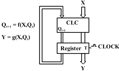
All types of numerical systems can be obtained from the sequential logic system presented in figure 1.
Register
Qt+1
T
CLC X
Y Qt+ 1 = f(X,Qt)
Y = g(X,Qt)
CLOCK
Figure 1. The Logical Sequential System
The system’s characteristic functions can be explicitly expressed by: graphs, transaction tables, flow charts, wave form and their translations (each with its own theoretical nuances and/or practical approach). By using neural networks in the study of such systems, the combinative hazard is actually excluded. The behavior of the combinative logic circuit CLC is not time depending and it can be described by Boolean functions or binary algebra functions.
Boolean function can be explicitly expressed by logic tables of truth canonical forms S or P, Veitch-Karnaugh diagrams, Quinne Mc Cluskey etc. The most difficult problem in the classical paradigm of this systems’ approach is the minimization of the electronic system for the implementation of the given system, minimization which means to find the minimum functional system equivalent with the given one. In the case of the approach by neural paradigm the problem of minimization is implicitly solved by the conceptual philosophy of the neural networks, itself. In the classical paradigm applied to the approach of these systems the following minimization methods are used:
• Analytical method by using theorems of the Boolean algebra, starting from the logic expression of the characteristic functions and application of the Boolean theorems until the minimized forms are obtained;
• Reduction of the system’s state space by the partitioning of space into equivalence classes;
• Minimization of the combinative logic circuit associated to the system by one of the graphical methods of the Veitch-Karnaugh or Quinne Mc Cluskey diagrams.
In the classical paradigm of these circuits’ approach, starting from the general theory of the finite state systems FSS, the mathematical modeling conduct to:
• Classification of the digital systems;
• Mathematical description of the digital systems’ behavior;
• Establishment of the general design methods.
In general, any FSS can be mathematically descripted by a quintuples like: )
g , f , Q , Y , X (
S = ,
where:
• f : XxQ→Q - represents the transition function of the states, this function defines the modifying process of the states in a FSS, being dependent on the inputs and the system’s former state;
• g:XxQ→Y - represents the transition function of the outputs. In the Mealy model, g function shows that the outputs are modified according to the input functions of the FSS and the former state of the system. In Moore model, g function shows that the outputs depend only on the former states, that is : g :Q→Y . There is a rigorously, mathematically demonstrated theorem which says that the two models (Mealy and Moore) are equivalent.
The system described by this quintuple is maned with finite states whilst X, Y and Q are finite therefore discrete. The realm of time which doesn’t explicitly appear in the definition is also formed by the se of integer numbers
} t ,..., t , t {
T 1 2 N+1 where : t1 =0, t2 =1, t3 = 2, …, tN+1 = N and which correspond to the appearance of synchronizations impulses of the tact generator.
The characteristic functions f and g define the evolution of the FSS in time. These functions are represented by: transaction tables, transaction graphs and flow charts.
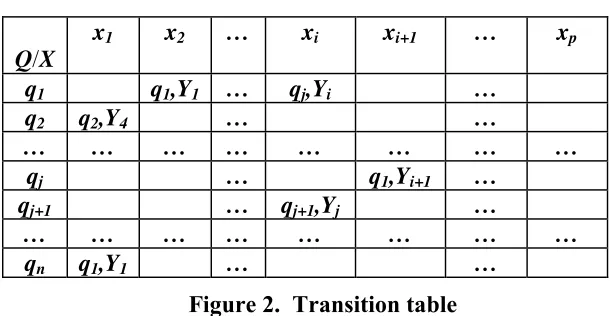
Transaction tables contain input variables in columns and components of the state matrix in lines. At the intersection of each column and line, the state and the next output are written, that is the value of function f and the value of function g separated by a comma, as in figure 2.
Q/X
x1 x2 … xi xi+1 … xp
q1 q1,Y1 … qj,Yi …
q2 q2,Y4 … …
… … … … … … … …
qj … q1,Yi+1 …
qj+1 … qj+1,Yj …
… … … … … … … …
qn q1,Y1 … …
Figure 2. Transition table
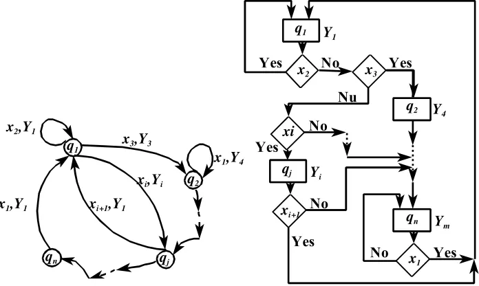
In this way the transition graphs contain the states of the FSS in nodes and the arches represent the determinations of inputs and outputs as in figure 3. For example, if S system is in q1 state and the x2 input has been applied, system S remains in the same state, if xi input has been applied the system S passes into state qj and if x3 input has been applied the system passes in state q3, state q1 is reached when the system is in state qnand the applied input is x1 , etc.
The transition flow charts of states (figure 4) contain in rectangles the states of system and the outputs of the system adjoining. The inputs xi are the testing conditions which establish the system’s evolution.
Thus if the system is in state q1 and has x2 as input, it will remain in state q1 and output Y1, if in state q1, x3 has been applied as input the system passes in state q2 having the output Y4, and if in state q1 , xi is applied as input the system passes in state qj having the output Yi and so on.
The classical paradigm of the approach of the FSS shows that such a system can be mathematically described by :S=(X,Y,M), where:
• X - represents the input space of the system;
• Y - represents the output space of the system;
• M :X →Y - represents the input-output function of the system (in case of electronic systems, function M is explicitly expressed by the wave forms obtained by oscillography).
2. Simulation of numerical systems by using neural networks
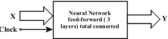
Due to the perfect functional similitude between neural networks of feed-forward type and numerical systems we shall see if it is possible to simulate numerical circuits and systems by using neural networks. Based on our research and the studied bibliography we have concluded that the fact is completely achievable. For the general case we propose the following simulating network of the integrated numerical circuits and systems presented in figure 5.
qj
qn
q2
q1
xi,Yi
xi+1,Y1
x1,Y1
x2,Y1
x1,Y4
x3,Y3
q2
x3
x1
qn Y m
No Yes
Yes
xi+1
qj Yi
No
Yes
xi q1
Y4
Nu
No No
x2
Yes
Yes
Y1
Y X
Clock
Neural Network feed-forward ( 3 layers) total connected
Figure 5. Neural network for the simulation of numerical circuits and systems
The neural networks inputs are represented by the set of input variables in system FSS X{ x1,x2,...,xp} and by the Clock. The presence of the tact signal is absolutely required for the synchronization of the stimulated system’s state change. The neural networks outputs are represented by the set of output variables of the FSS, that is Y{ y1,y2,...,ym }.
For the network’s training, specialized software, known in the literature, can be used, software which doesn’t occur any problem in exploitation.
After the network has been well trained and checked the next phase is the hardware implementation and testing in the new functional conditions. As regards the steps of design we propose the following design method:
• Step 1: Establishment of the truth table for the description of the FSS functioning and graphical achievement of the transition flow chart of system’s states.
• Step 2: Selection of the neural network of feed-forward type, totally connected, with 3 layers, establishment of neurons in the input layer, output layer and the hidden layer. The number of neurons in the input player has to be equal with p+1 (x1,x2,...,xpand tact), in the output layer should be m (y1,y2,...,ym), and for the hidden layer we have concluded that the number is: (p+m+1)*2/3.
• Step 3: Training of the chosen neural network by using specialized software e.g. Mathlab or WinNN.
3. Tests and practical applications
For practical application I used an older project that was applied at IMMN Zlatna Factory. This real application was developed by a team lead by myself. The logical diagram for the function of this FFS is presented in figure 6.
The states list for shortcircuit measuring machine
A = Pause state
B = Autotest state (SFA=output signal) C = Machine cicle state (SFC=output signal) D = Execute retrat DM state (SFR=output signal) E = Malfunction signal state (SFS=output signal)
Input signal: CM = Maisure signal Signals: MC = Correct maisure SFA = End of autotest SFC = End cicle maisure state SFR = End retreat DM state SFS = End malfunction signal state
LP = position limitator (LP=1 enganged, LP=0 not engaged)
The logical evolution of states of the maisure controller
A: = D •SFR + E • SFS B: = A • CM • LP C: = B • SFA • MC D: = C • SFC
E: = B • SFA • MC Where: MC= NON(MC)
Deprnding on the state variables
A = X2 • X1 • X0 Figure 6. The logical diagram for practical example FSS
LP
Figure 7. Classical implementation of states generator
For each of the states of system the corresponding logical diagram can be created and also it’s truth table for the corresponding sub-states. For the implementation of the FSS with the use o neural networks, a neural network of feed-forward type was used witch three layers total connected. This network has 17 input neurons (3 for the states generator, 2 for B state, 3 for C state, 2 for D state, 1 for D state, 1 for E state, 1 for clock generator and 5 for the position limits), 12 neurons in the hidden layer and 9 neurons in the output layer (3 for the controller engine command, 4 for the measure controller command, 1 for display the read values and 1 for permission of relocation of DM). The training of the neural network was done by the use of WinNN product.
4. Conclusions
conduct to the achievement of complex neural finite state automates, as first stage in the achievement of neural computing systems.
References:
[1] Park Young-Moon, Choi Myeon-Song, Lee Kwang Y.: An Optimal Tracking Neuro-Controller for Nonlinear Dynamic Systems, IEEE
Transactions on Neural Network Vol.7, No. 5, September 1996, p. 1099-1110. [2] Joldeş R., Ileană I., Rotar C.: Utilization of neural networks in the
simulation of combinational logical circuits, Acta Universitatis Apulensis, Mathematics-Informatics, Alba Iulia, No. 3, 2002, p. 65-68.
Authors:
Emil Olteanu - „1 Decembrie 1918” University of Alba Iulia, E-mail address: eolteanu@uab.ro
Remus Joldeş - „1 Decembrie 1918” University of Alba Iulia, E-mail address: rjoldes@uab.ro