Detection and Analysis Tool Wear of Carbide Flat End Mills 2T, 3T, 4T
for Surface-Rough Machining by Third Wave AdvantEdge
TMSoftware
Simulation.
Arranged as a requirement to completing undergraduate program in mechanical
engineering, engineering faculty
Dony Irvan Siswanto
D200122001
MECHANICAL ENGINEERING DEPARTMENT
Engineering Faculty
UNIVERSITAS MUHAMMADIYAH SURAKARTA
APPROVAL SHEET
Thii
find
Rcpqth.
ta
clrrcrd
*ce6d
rodkgdi:sd
ty
secsviss,
lffi,iDg
ty
facgdaf
Iledcd
E&gi"€Eiry
Dcp4hd Wui
ldi@
ef
Tecfutogr
ad
l{rsd
of
tr&ciakal
F'ghnarng
d@ffi
L}uhcrsiesMottr',.'qr&
&ra&atr-Ccrydbt
:kylrre S&rEe
rytn!al36lyl0*fI!00f
Psdi!
i
&y
: Tucrdayib
:22i,i620r6
Ss1rvixr
I
Sqerviw'll
.4>
rt+
{ASlrDri
zJvou-tue,
)
--re,
\ta'r
tirEee,
Sf-ltLErE;.,ltJ
KrEig,
Itrad
ofMecSakal
Frg
DEp{lnd
t,livlniue
iemndlnh
Su*ztr
rrri
lUiitorb
Brru XlnilL
$r,
,l,,s.-
Pl-D)
I&ad of
fde&ical
Fag
Disd{eftt
VALIDAIION
SHEETTnb
Fiflf
Rcpo.rtc
bao
ec*rce(
ecpd
ad
tgdizrd
fu
.rytlvir*r,
ll'l,t*iqg
by
}&ad
qf
M(E[uiGrl
*"ffi
D!t[!sd
XIrBi
brdrd!
of
Techologr
r6d
}lcad
of
l,ktui.d E4lEiq
UriyclsitssMuhmmdiyah
Su*sta
C@tv :Donykrel$aruo
tt99l56t3arD}$ti!&t
Prdin
.dsy :TE.k!l
dxe :21!.,ld
2ill6
\'
Sr+svbu
f
{
Aalr.
Dri
fsriq,
Ilead of
M*hial
&lg
De.rttrd
UnivcGd*
MrrF
rl
sdij€eSr.frfil
(Tr,ttiaotl*knfraaf,i5I,
.!IG.I,LD)
!!Ed
crflt{ctlrei*l
Fas
DFuent
WEi
SlpcrvistrL
A>
rt+
(h?
1
Detection and Analysis Tool Wear of Carbide Flat End Mills 2T, 3T, 4T for Surface-Rough
Machining by Third Wave AdvantEdge
TMSoftware Simulation.
1
Dony Irvan Siswanto,
2Agus Dwi Anggono,
3Zou Ye
1Bachelor Student, Dept. of Mechanical Engineering, Wuxi Institute of Technology, China, 2Mechanical Engineering Universitas Muhammadiyah Surakarta, 3Mechanical Engineering Wuxi Institute of Technology.
ABSTRACT
Surface rough-machining is one of the important process before finishing process. For the finding the
best result of rough-
machining’s quality criteria, least machining time and least remaining volume without
making worse of tool wear after roughing so need detection and analysis optimum parameter proses without
ignoring tool wear’s aspect. Cemented Carbide flat End
-mill with 2, 3, 4 Flutes used as the main case parameter
study with Al 7075 T6 as the workpiece materials, by calculation and bring it to Third Wave Advant Edge
TMSystems Software simulation some data become recommendation production parameters as the final conclusion.
Proses kekasaran permukaan merupakan salah satu proses penting sebelum proses finishing. Untuk menemukan hasil terbaik dari kriteria kualitas kasar -mesin ini, waktu mesin setidaknya dan volume tersisa sedikit tanpa membuat lebih buruk memakai alat setelah hidup seadanya sehingga perlu deteksi dan analisis optimum Proses parameter tanpa mengabaikan aspek memakai alat ini. Semen Carbide datar End-pabrik dengan 2, 3, 4 Flutes digunakan sebagai studi parameter kasus utama dengan Al 7075 T6 sebagai bahan benda kerja, dengan perhitungan dan membawanya ke simulasi Gelombang Ketiga Advant EdgeTM Sistem Software beberapa data menjadi parameter produksi rekomendasi sebagai kesimpulan akhir.
Key words: Rough-machining (
proses kekasaran permukaan), Cemented Carbide End-mill (
KarbidaEndmill
), Al 7075 T6, Third Wave Advant Edge
TM.
.
INTRODUCTION
In the modern era, development in the fields of engineering, especially engineering technology is progressing very rapidly. The development of science is a major factor in developing of technology in the field of engineering sciences. So, in the case the speed and accuracy are the challenges that faced today.
Machining plays important role in producing products. Milling is the most widespread metal removal process in metalworking industry. Manufactured products qualities are determined by their surface quality. The high friction between tool and work piece leads to high temperatures, tool wear, and poor surface quality [1].The end-milling process is one of the most widely used material removal processes in industry [2] Others, the operation of the machine with the type of automated or computerized also needed skill or knowledge in how to operate it. Beside that during the production some problem happened, like tool broken, the
requirement of finishing product is not same with the expected result, the duration of production take long time and others some unexpected problems.
Some studies have observe the problem that face in the field of production. Current machining processed and cutting tool designs are slow and too conservative, leading to high cost and significant waste [3]. Tool failure may result in losses in surface finish and the dimensional accuracy of a finishes part, or possible damage to the work piece and machine [4]. Because of that needs some optimization in every area.
end-2
mills are varied and have each purpose of every types to solve diverse problem in production.
Agnew,P.J. said in his paper ―for example, when doing a slotting operation, unless doing a light cut of about 2D or less, it is best to use a two- or three-fluted end mill. The general rule is use less flutes for deeper cuts, with four or higher flutes for light cuts. The reason for this is the venerability of chip packing that can lead to destruction of the end mill [6]. Finally, all of that are basically interesting to make research in this field of finding optimization and simulation before machining processes.
There are some studies as the reference of this research. Those are researches about optimization carbide end mill with analyze and simulation. Design and developing of a multi-purpose carbide end mill (MP-CE) to suit all kinds of cutting proposes which will uncover the background information on different kinds of end mill structure, tool materials and various surface treatment on the cutter [8].
Generalized modeling of milling mechanics and Dynamics – Helical End Mill is study about predicted and measured cutting forces, surface roughness and stability lobes for ball, helical tapered ball, and bull nosed end mills are provided to illustrate the viability of the proposed generalized end mill analysis [9].
The research by Kuttolamadom,M[10] is about prediction of the wear and evolution of cutting tools in carbide/Ti-6Al-4V machining Tribosystem by volumetric tool wear characterization and modelling have proven that straight tungsten carbide wear when machining Ti-6Al-4V is mechanically-driven at slow surface speeds and thermally-driven at high surface speeds.
Optimal Selection of Tools for Rough Machining of Sculptured Surfaces is another research that focused on Evaluation of the effect of depth of cut and stepover, as major machining parameters and their influence on machining time and remaining volume and real time experiments showed that simulation results are really close to reality and thus CAM software is an adequate tool for optimization purposes [11].
And the research which using TWS AdvantEdge for finding optimization both in effective time reduce and also tool wear. Simulating steel machining AdvantEdge user defined and user defined yield custom material options [12] and the path for improvement in Third Wave Software [13].
ANALYZE METHOD
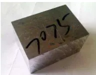
Before input data to the TWS software. Analyze the all specimens is necessary to approaching in the real condition. Material that used in this experiment is Al-7075 T6 80x50x40 mm. and after getting final result, cheking the data with real machining to real check the effect after optimalization.
Figure speciment of workpiece material Al-7075 T6.
3.2.2 Carbide Flat Endmill
In the real machining after finding optimum parameter processing, the cutting tools that use is ø8 mm with 3-flutes.
Figure Flat End-mill ø8 3T , Tool-length view. Flutes view.
All of preparation and consideration are used to realize the result of optimalization by simulation. And the real machining treatment are used to become initial data parameter for the next consideration. And all the equipment beside those already explained above others are
Figure workpiece clamped in the Chuck,.cutting tool with tool holder.
Initial simulation. Exact effect of tool wear with selected machining. The parameter above is used to looking for the tool wear before optimization. So, it’s become first data or common data of initial parameters. 3D plug milling simulation is use to know the tool wear both of three types of tools.
Simulation and experiment 1. Finding optimal feed rate by TWS simulation. Because rough process are so complicated path line, the simulation taken by using 3D pocket milling. 2 -F lu te s-3 F lu te s-4 F lu te s
n F a b
rpm mm/min mm mm
s ame ----» -1 5 % ----» s ame ----» s ame ----»
3000 595 1 6
3000* 700* 1* 6*
[image:6.612.416.512.47.122.2] [image:6.612.314.606.171.259.2]3 s ame ----» + 1 5 % ---» s ame ----» s ame ----»
Simulation and experiment 2. From the result of this simulation can be used for finding optimal and effective deep of cut (DOC). Other parameters are same and only change number DOC to finding effect of DOC to another consideration.
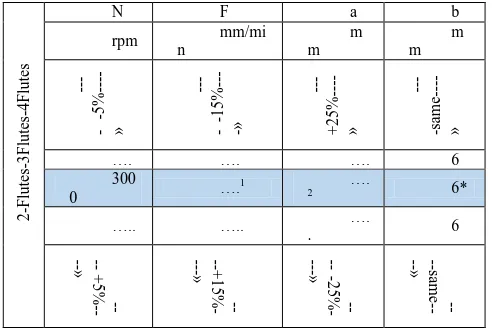
Simulation and experiment 3. The data
recommendation above use to predict the continues-changes data to finding optimization parameter’s process without ignoring tool life. And the approaching way to finding continues parameter data are:
2 -F lu te s-3 F lu te s-4 F lu te s
N F a b
rpm mm/mi n m m m m ---- -5% ----» ---- -15% ----» ---+ 2 5 % ----» ----same ----»
…. …. …. 6
300
0 ….
1 ….
2 6*
….. ….. . …. 6
+ 5 % --» --+ 1 5 % - ---» -2 5 % - ---» --same --»
Finally all the result collect to the one data base and making comparison for making conclusion. Also from the first simulation data until the last. Showing the comparison as prove of optimizing is done.
DATA ANALYZE
In this experiment, the changes variable data is feed rate value. Based on formula, feed rate give significant effect to the total time, both estimate time and metal removal millimeter cubic per minute. And the result are shown by graph.
It shown correlation of cutting time (t) with tool wear (ẘ). Another side is correlation between feed per tooth (f) and tool wear (ẘ).in order to finding effective- safety feed rate, make cross-section time per ẘ and f per ẘ. and the point is t=8, f=0,1 and ẘ=0,00065.
ẘ= 0,00085 is in different area both on three tools. By interpolation method feedrate value can be determined and the result shown below
The value of F both 2,3,4 Flutes become consideration in the next prediction. Final data in experiment 1 shown that changes feed rate give effect on the total production time and the increasing the number of flutes followed by increasing feed rate value in same DOC and spindle speed condition.
In this experiment, changing depth of cut value is used to finding optimum DOC value without discharging tool wear value (ẘ). DOC basically not changing cutting time but total metal removing time (mm3/min). And the result are shown by graph. It shown correlation of tool wear (ẘ) with DOC (mm) . Another side is correlation between metal removal rate (mm3/min) and DOC (mm).in order to finding optimum depth of cut value, make cross-section ẘ per DOC and MR per DOC. and the point is DOC=0.75, MR=3,xx and ẘ=0,075.
As the same way, to finding depth of cut by interpolation with tool wear value is 0,075. And the result shown in table below
From the calculation result above the analysis going to the simulation, the simulation parameter and the result are
a) Parameters
- N-Flutes = 4
- Feed rate = 1100 mm/min
- DOC = 1,22 mm
b) Result
Figure result of simulation . (a).temperature-contour. (b) . X-Y-Z Force. (c). Power-Torque-Temperature.
The result shown that with using the parameters above the cutting tool in the best condition for machining.
2-Flutes 3-Flutes 4-Flutes
ẘ F ẘ F ẘ F
[image:7.612.37.283.302.467.2]4
Finally the data above to finding continues data changes of parameter cutting process. In this graph shown that the recommendation of choosing value of each parameters, such as spindle speed, feed rate, depth of cut and also the tool with the n-number of flutes. And the range of optimum parameter which good in tool wear are check in the Third Wave System AdvantEdge software.
Graph Correlation between spindle speed, feed rate and Depth of cut
One of prove that the calculation and the result can be recomendation are shown by simulation and real machining analyze ( 3-flutes with different parameter).
CONCLUSION
1. Optimization helps in determining the parameters that result in both improved production rate and enhanced surface quality before finishing process. In the present work influences of end milling parameters namely Spindle speed, Feed Rate, Depth of cut, Step over and Machining time (MT) are studied with tool wear consideration.
2. Increasing n-flutes number is directly proportional with feedrate value and inversely proportional with feed per tooth, if the number of feed rate are same increasing n-flute
number has no effect on both total production time and metal removal rate but giving effect on tool wear( stress and force) in each teeth .
3. Changing feedrate value give significant effect on the total production time, and the increasing the number of flutes followed by increasing feed rate value in same DOC and spindle speed condition. Opposite with that, increasing depth of cut value also followed by increasing metal removal rate as well in the same spindle speed rotation condition.
4. In the same spindle speed value 3000 rpm, the optimization rouh-machining process parameter (safety-effective production) for 2T are 550 mm/min feed-rate value with 2,45 mm depth of cut, 825 mm/min for 3T with 1,63 mm depth of cut, 1100 mm/min for 4T with 1,2 mm depth of cut. And the changes the value of spindle rotation be followed by changing feedrate and depth of cut respectively.
REFERENCES
[1] p. Chockalingam and l. H. Wee, ―surface roughness and tool wear study on milling of aisi 304 stainless steel using different cooling conditions,‖ int. J.
Eng. Technol. Vol. 2 no. 8, august, 2012. Melaka malaysia,
vol. 2, no. 8, pp. 1386–1391, 2012.
[2] b. . Damazo, m. . Dutterer, and m. . Kennedy, ―a summary of micromilling studies,‖ 1st int. Conf. Gen. Meet. Eur. Soc. Precis. Eng. Nanotechnology,bremen, ger., 2001.
[3] c. Dr. Troy d.marusich, sustainable manufacturing_u.s. doe advanced manufacturing office peer review meeting. Clifornia santa barbara: third wave systems inc., 2014.
[4] x. Li, b. S. Lim, j. H. Zhou, s. Huang, s. J. Phua, k. C. Shaw, and m. J. Er, ―fuzzy neural network modelling for tool wear estimation in dry milling operation,‖
annu. Conf. Progn. Heath manag. Soc., pp. 1–11, 2009.
[5] o. Gilbert, ―force balancing an advanced toolpath.‖ Connecticut center for advanced technology,inc., usa.
[6] p.j. agnew, ―what to consider when evaluating solid carbide end mill machining.‖ .
[7] y. Yang, x. Li, p. Jiang, and l. Zhang, ―prediction of surface roughness in end milling with gene,‖
proc. 41st int. Conf. Comput. Ind. Eng., pp. 441–446, wuhan
china.
[8] h. Ku and w. C. Chia, ―design of multi -purpose carbide end mill,‖ vol. 67, no. 2, pp. 34–40, 2006.
[9] s. Engin and y. Altintas, ―generalized modeling of milling mechanics and dynamics: part i - helical end mills,‖ univ. Br. Columbia dep. Mech. Eng., no. 1997, 1998.
[10] m. A. Kuttolamadom, s. Hamzehlouia, and m. L. Mears, effect of machining feed on surface roughness in
0 1000 2000 3000 4000 5000 6000
0 2 4 6 8 10 12 14 16 18 20 0 500 1000 1500 2000 2500 3000 3500 4000 4500 5000
0 1000 2000 3000 4000 5000 6000
ẘ ( .mm.K.α/oK.min)
D O C ( m m ) F ( m m /m in )
Spinde speed (Rpm)
Corelation between Spindle Speed, Feedrate and DOC
5
cutting 6061 aluminum. Clemson university - international center for automotive research copyright, 2010, pp. 1–19.
[11] p. Spanoudakis, n. Tsourveloudis, and i. Nikolos, ―optimal selection of tools for rough machining of sculptured surfaces,‖ proc. Int. Multiconference eng. Comput. Sci. 2008 vol ii imecs 2008, 19-21 march, 2008, hong kong, vol. Ii, pp. 19–21, 2008.
[12] t. H. C. Childs, ―simulating steel maching advantedge user defined and user defined yield custom material options.‖
[13] troy d. Marusich, ―the path for improvement in third wave software,‖ 2010.
[14] c. Saikaew and p. Baowan, ―surface finish improvement in ball nose end milling by optimizing operating conditions for different cutting times,‖ indian j. Eng. Mater. Sci., vol. 22, no. February, pp. Pp.38–50, 2015.
[15] j. Kechagias, p. Kyratsis, and n. Mastorakis, ―on prediction of surface roughness of al7075alloy during slot milling using nn modeling,‖ recent adv. Mech. Mater. Mech. Eng. Chem. Eng., pp. 98–107.
[16] v. S. Jatti, r. Sekhar, and r. K. Patil, ―study of ball nose end milling of lm6 al alloy : surface roughness optimisation using genetic algorithm,‖ int. J. Eng. Technol., vol. 5, no. 3, pp. 2859–2865, 2013.
[17] w. D. S. M. Ponnala and k. L. N. Murthy, ―modeling and optimization of end milling machining process,‖ ijret int. J. Res. Eng. Technol., pp. 430–447, 2012.
[18] a. A. Syah, e. Sutikno, r. Raharjo, j. Teknik, m. Fakultas, and t. Universitas, ―pengaruh feed rate dan depth of cuts terhadap surface roughness pada proses milling dengan,‖ jurusan teknik mesin fakultas teknik universitas brawijaya.
[19] ja. Schey, introduction to manufacturing process 2nd, second ed. New york, 1987.
[20] g. S. I. Hesler, ―investigating the mechanisms of diamond tool wear cutting ferrous materials using a quantitative study of machining parameters.‖
[21] b. Sick, ―review on-line and indirect tool wear monitoring in turning with artificial neural networks,‖ a rev. More than a decad. Res. Mech. Syst. Signal process., pp. 16(4), 487–546,, 2002.
[22] j. Qu and a. J. Shih, ―analytical surface roughness parameters of a theoretical profile consisting of elliptical arcs,‖ in machining science and technology, vol. 7, no. 2, united states, 2003, pp. 281–294.
[23] t. G. Stoebe and a. West, ―iron and steel — properties and applications.‖ 2009.
[24] alcoa inc., ―alcoa mill products-alloy 7075 plate and sheet.‖
[25] sede legale e amministrativa/headquarters and administration office, aluminum 7075-t6; 7075-t651. Modena: crp meccanica s.r.l.
[26] a. D. Isadare, b. Aremo, m. O. Adeoye, o. J. Olawale, and m. D. Shittu, ―effect of heat treatment on some mechanical properties of 7075 aluminium alloy,‖ mater. Res., vol. 16, no. Sep,3rd, pp. 190–194, feb. 2013.
[27] d. Singla and s. R. Mediratta, ―evaluation of mechanical properties of al7075-fly ash composite material,‖ int. J. Innov. Res. Sci. Eng. Technol., vol. 2, no. April,4th, pp. 951–959, 2013.
[28] v. Songmene, r. Khettabi, i. Zaghbani, j. Kouam, and a. Djebara, ―machining and machinability of aluminum alloys,‖ canada, 1983.
[29] a. Gatto, e. Bassoli, and l. Iuliano, ―performance optimization in machining of aluminium alloys for moulds production : hsm and edm,‖ university of modena and reggio emilia-politecnico di torino,italy, 2010.
[30] h.-t. Young, l.-c. Chuang, k. Gerschwiler, and s. Kamps, ―a five-axis rough machining approach for a centrifugal impeller.‖
[31] j. G. Parmar and p. A. Makwana, ―prediction of surface roughness for end milling process using artificial neural network,‖ int. J. Mod. Eng. Res., vol. 2, no. 3, pp. 1006–1013, 2012.
[32] chia wee chong, ―research and development of multi purpose carbide end mill,‖ 2005.
[33] t. Conical cutting tool, ―end mill attributes and terminology commonly used industry language and
definisions.‖ [online]. Available:
http://www.conicalendmills.com/wp-content/uploads/2014/10/end_mill_attributes_terminology.p df. [accessed: 15-mar-2016].
[34] m. Kuttolamadom, ―prediction of the wear & evolution of cutting tools in a carbide / ti-6al-4v machining tribosystem by volumetric tool wear,‖ 2012.
[35] rao, manufacturing technology vol-ii 2e. Tata mcgraw-hill education. Isbn 978-0-07-008769-9., 2009, p. 30.
[36] j. R. Davis, asm international. Handbook committee (1995). Tool materials. Isbn 978-0-87170-545-7., 1995, p. 289.
[37] k. Kadirgama, b. Mohammad, h. Al-ani, and m. M. Noor, ―cutting force prediction model by fea and rsm when machining hastelloy c-22hs with 90 ° holder,‖ j. Sci. Ind. Res., vol. 67, no. June, pp. 421–427, 2008.
[38] tws_user manual, third wave system advantedge user manual version 4.8 (third wave system,minneapolis). 2007, pp. 8–20.
[39] c. Constantin, s. Croitoru, g. Constantin, and e. S. T. R. Ă. Jescu, ―fem tools for cutting process modelling and simulation,‖ u.p.b. sci. Bull., ser. D, vol. 74, 2012.
6
[41] saurabh r. Virkar a, ―numerical simulations and analysis of ductile mode micro,‖ kalamazoo, michigan, 2010.
[42] tecplot inc., tecplot.360 2011 user ’ s manual. Bellevue u.s: tecplot,inc., 2011.
[43] copyright © 1995-2015 third wave systems., third wave advantedge user’s manual. Advantedge © third
wave systems windows © microsoft corporationnx®siemens product lifecycle management software inc., 2015.
[44] uddeholm corrax, ―cutting data
recomendations.‖ [online]. Available:
http://www.uddeholm.com/files/cutting_data_corrax_eng.pd