DESIGNING BANK BUILDING 10 FLOORS
WITH 1 BASEMENT USING PARTIAL DUCTILE SYSTEM
IN SURAKARTA
Publication Papers
in partial fulfillment of the requirement
for the degree Bachelor of Civil Engineering
by :
FARID TEGAR ASHARI
NIM : D 100 102 011
to
CIVIL ENGINEERING DEPARTMENT FACULTY OF ENGINEERING
MUHAMMADIYAH UNIVERSITY OF SURAKARTA
APPROVAL
SHEET
DESIGNING
BAYK BUILDING
10TLOOR
WITH
1BASEMENT
USING
PARTIAL DUCTILE
SYSTEM
IN SURAKARTA
Publication
Papers
1
Proposed and is kept on Final Exam
Final Project on face
Examination
Official
On 20
Mei
2015by:
FARID TEGAR ASHARI
NIM:
D100102011
a
Structure
of
Examination
Official
:,rW*
H.
Budi
Setiawan. S.T.M.T.
NIK:785
Final Project accepted of the require,ments For the degree Bachelor
of
S-lCivil
Engineering
l1 Supervisor
NIK:
732Examinator
NIK:783
NIK:
732DESIGNING BANK BUILDING 10 FLOORS
WITH 1 BASEMENT USING PARTIAL DUCTILE SYSTEM IN SURAKARTA
Farid Tegar Ashari
Civil Engineering Department Faculty of Engineering Muhammadiyah University of Surakarta
ABSTRACTION
Final project is meant to plan a reinforced concrete structure 10 with 1 basement floor, which is the building to the bank of the region Surakarta (earthquake region 3) which stands on solid ground and is based on ISO 1726-2002 with the value of ductility factor (μ) = 2.5 that includes the partial ductile. The purpose of this thesis is to obtain a comparison or efficiency of the planning structure based on the three dimension building, which includes structural mechanics analysis, the distribution of shear loads or seismic and needs reinforcement.
Design of reinforced concrete structures using quality materials that include concrete quality f'c = 25 MPa, the quality of steel fy = 300 MPa and frame the horses using quality steel used Bj 41. Regulation as reference includes PPIUG-1983, SNI 03-1729- 2002, PPBBI-1984, PBI-1971, SNI 03-2847-2002. Analysis of structural mechanics using "SAP 2000 v.14" 3 dimension. Mathematical calculations using the "Microsoft Excel 2007". While the depiction using "AutoCAD 2007".
The results of final project as follows :
1).
Roof structure using steel frame frame profile 2L50x50x5 and 2L50x50x6.2).
The thickness of plate floor (1-9) 12 cm with main reinforcement D10 and divisor reinforcement dp8. To plate used stairs and landing plate 12 cm thick with main reinforcement D12 and divisor reinforcement dp8.3).
Beams with dimensions 400/700 mm with main reinforcement D22 and shear reinforcement 2dp8. Column with dimensions 500/500 mm with main reinforcement D25 and shear reinforcement 2dp10.4).
Pile cap using size 4x4 m2 thick 100 cm with reinforcement D25-100 mm. Piles with dimensions 35 / 35 cm with the main reinforcement 4D22 and shear reinforcement 2dp10-140.1
INTRODUCTIONSurakarta is a city that has been growing, the general population there were civil servants,
businessmen, bank employees and others. Generally workspace bank building does not move
because it is equipped with supporting facilities like space for the archives, meeting rooms, lunch
rooms and other supporting activities. So that the safety and comfort need to be considered.
Designing a bank building with 10 floors and 1 basement was made because of the development of
increasingly rapid Surakarta city and followed by a number of investors who entered both
domestically and from abroad. And so we need adequate work space, while it will need more work
space that is not matched with the available land in the city of Surakarta, thus resulting in the need
for the planned layout of work space vertically in order to carry out activities of economic activity
in the city of Surakarta.
Avoid widening the discussion, in the preparation of this thesis is limited to the following
issues :
1. The discussion includes the calculation of the roof structure (steel frame) and reinforced
concrete structures (plate floors, stairs, beams, columns and foundations).
2. The designing building is a ten floors bank building with one basement in Surakarta using
partial ductile system with ductility factor μ = 2,5 and a reduction factor of R = 4,0.
3. Quality of concrete f'c = 25 MPa and quality steel for division reinforcement fy = 240 MPa as
well as to longitudinal reinforcement fy = 300 MPa.
4. In this use design regulations as follows :
a. Peraturan Pembebanan Indonesia Untuk Gedung, 1983. b. Peraturan Beton Bertulang Indonesia (PBI) 1971.
c. Pedoman Perencanaan Ketahanan Gempa Untuk Rumah dan Gedung (PPKGURG-1987). d. Standar Perencanaan Ketahanan Gempa Untuk Struktur Bangunan Gedung (SNI
03-1726-2002).
e. Tata Cara Perhitungan Struktur Beton Untuk Bangunan Gedung (SNI 03-2847-2002). f. Tata Cara Perencanaan Struktur Baja Untuk Bangunan Gedung (SNI 03-1729-2002).
LITERATURE
Ductility is the ability of a building structure to undergo post-elastic deviation large and
repeatedly back and forth due to earthquake loads upon loads earthquake that caused the first
meltdown, while maintaining sufficient strength and stiffness, so that the structure of the building
is still standing, though had been on the verge of collapse (SNI 03-1726-2002).
Based on SNI 03-1726-2002 there are 3 planning system, namely :
a. Full Elastic System, namely the structural design of buildings using a value of μ = 1,0 or R = 1,6.
b. Partial ductile system, the structural design of buildings using a value of μ = 1,5 to 5,0 or R = 2,4 to 8,0.
2
Guidelines for calculation of concrete structures in Indonesia, listed in the Standard
Procedure for Calculation of Concrete Structures for Buildings SNI 03-1726-2002. Guidelines for
calculation of concrete structures in Indonesia, listed in the Standard Procedure for Calculation of
Concrete Structures for Buildings SNI 03-1726-2002. Some components of the structure includes a
strong need, strong and robust nominal or robust plans available
According to Article 11.2 of SNI 03-2847-2002, so that the structure and strength of
structural components qualified and suitable to be used on a variety of combinations of load, then
it must be filled with the provisions of the factored load combinations as follows:
a. U = 1,4 D
b. U = 1,2 D + 1,6 L + 0,5 (A or R)
c. U = 1,2 D + 1,0 L + 1,6 W + 0,5 (A or R) U = 0,9 D + 1,6 W
d. U = 1,2 D + 1,0 L + 1,0 E U = 0,9 D + 1,0 E
Earthquake loads is one burden that must be taken into account in the designing of the
building structure, particularly for earthquake-prone areas. In this designing guidelines earthquake
loads calculated by SNI 03-1726-2002.
BASIS THEORY
1. Designing Steel Frame Roof Structure
The burdens are calculated on gording include dead loads (due to its own weight and load
gording roof cover), live load and wind load. Steel profiles are used to gording canal profile.
2. Designing Structure Floor Plates and Stairs
Plate is a flat field structure (not curved) which when viewed in three dimensions has a
thickness much smaller than the size of the field plate.
In order risers can be used easily and comfortably
3. Designing Structure Beams With Partial ductile System
In designing beam analysis includes calculation of beam longitudinal reinforcement and shear
reinforcement shear beam.
4. Designing Column Structure With Partial Ductile System
In the structural design analysis column calculations include longitudinal column
reinforcement, shear reinforcement columns and column moments available.
5. Designing Foundation
Calculation heavy duty pile count tries a fall pile to it compiler charges utilize material of
3
DESIGNING METHODDesigning data structures include the following :
a. Data collecting
b. Design frame and stair
c. Design beam and column
d. Determine sufficiency beam and column
e. Foundation design
f. Make sketch detail
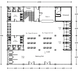
RESULTS DESIGN
Rg. Tunggu Laki-Laki Rg. Tunggu Perempuan
+ 0,00
Lobby Lift Teller 1
Banking Hall Lobby
ATM
Toilet Laki-Laki
Toilet Perempuan
Tangga
Lobby Lift
Khazanah
Figure V.1. Building sketch
A. Roof structure planning
Roof structure using the cover of roof a tile. From the results of calculation used gording
cannal profile C150x50x20x2,3 and roof frame elbow profile 2L50x50x5 and 2L55x55x6. Tool connecting
4
2L 50x50x5 2L 50x5 0x5 2L 50x5 0x5 2L 5 0x 50 x 5 2L 55x5 5x6 2L 55x5 5x6 2L 50x50x52L 50x50x5
2L 50x50x5 2L 5 0x 50 x5 2L 50x50x5 2L 50x5 0x5 2L 50x5 0x5
2L 50x50x5 2L 50x50x5 2L 50x50x5
2L 55x5 5x6 2L 50x50x5 2L 50x5 0x5 2L 50x5 0x5 2L 5 0x 50 x 5 2L 55x5 5x6 2L 55x5 5x6 2L 50x50x5
2L 50x50x5
2L 50x50x5 2L 5 0x 50 x5 2L 50x50x5 2L 50x5 0x5 2L 50x5 0x5 2L 50x50x5 2L 50x50x5 2L 50x50x5 2L 55x5 5x6 2L 50x5 0x5
Pelat kopel 90x90x8
Cannal C 150x50x20x2,3
Usuk Kayu 5/7
Genteng Kodok Reng 2x3 Kerpos
Figure V.2. Steel frame
B. Planning plate
A
A B A A A A
A
B A A A A A
A
A A A A A A
A
A A A A A A A
Figure V.3. Plate sketch
Table V.1.
Reinforcement and moments plan plate
Type
plate
M
Need moments
(kN.m)
Main
reinforcement
Divisor
reinforcement
Plan momment
(kN.m)
A
M lx
3,37118
D10 - 140
-
9,887
M ly
0,98669
D10 - 140
-
8,244
M tx
-6,82459
D10 - 140
D8 - 180
9,887
M ty
-4,68677
D10 - 140
D8 - 180
8,244
B
M lx
1,53485
D10 - 140
-
9,887
M ly
0,29235
D10 - 140
-
8,244
M tx
-3,03315
D10 - 140
D8 - 180
9,887
M ty
-2,08301
D10 - 140
D8 - 180
8,244
5
M ly
0,23681
D10 - 140
-
8,244
M tx
-2,45685
D10 - 140
D8 - 180
9,887
M ty
-1,68724
D10 - 140
D8 - 180
8,244
C. Basement walls
Table V.2.
Reinforcement and moments plan basement walls
Type
plate
M
Need moments
(kN.m)
Main
Reinforcement
Divisor
reinforcement
Plan momment
(kN.m)
E
M lx
28,25696
ɸ12
- 100
-
36,596
M ly
13,34357
ɸ12
- 100
-
33,992
M tx
-59,65359
ɸ16
- 100
ɸ10
- 150
61,986
M ty
-44,74019
ɸ16
- 100
ɸ10
- 150
55,813
D. Basement floor
Table V.3.
Reinforcement and moments plan basement floor
Type
plate
M
Need moments
(kN.m)
Main
Reinforcement
Divisor
reinforcement
Plan momment
(kN.m)
F
M lx
3,65072
ɸ10
- 100
-
17,418
M ly
3,65072
ɸ10
- 100
-
15,911
M tx
-9,03989
ɸ10
- 100
ɸ10
- 150
17,418
M ty
-9,03989
ɸ10
- 100
ɸ10
- 150
15,911
E. Stairs structure
Table V.4.
Reinforcement and moments plan stairs structure
Stick
Area
Need
moments
(kN.m)
Main
Reinforcement
(Calculate)
Main
Reinforcement
(Use)
Divisor
reinforcement
Plan
momment
(kN.m)
1 = 4
Left
-19,651
ɸ12
- 90
ɸ12
- 90
ɸ8
- 150
20,958
Field
9,926
ɸ12
- 150
ɸ12
- 90
ɸ8
- 150
12,985
Right
-12,393
ɸ12
- 150
ɸ12
- 90
ɸ8
- 150
12,985
2 = 3
Left
-12,393
ɸ10
- 100
ɸ10
- 90
ɸ8
- 150
13,650
Field
-1,546
ɸ10
- 150
ɸ10
- 90
ɸ8
- 150
11,027
6
F. Beam structure
Beam structure calculation results can be seen in the following figure :
4 D22 4 D22 6 D22 5 D22 5 D22 5 D22 2dp 8-180
2dp 8-140 2dp 8-140
2 D12 2 D12
Tumpuan = 1/4. L
Sendi plastis = 2. h
400 700 60 50 60 50 6 D22 5 D22 400 700 60 50 60 50 4 D22 4 D22 2dp 8-140
2 D12 2 D12
2dp 8-180 400 5 D22 5 D22 2 D12 60 50 60 50 2dp 8-140 700 ?d ?dh
h balok > 300 mm harus diberi tulangan
montage 2 D12
Tumpuan = 1/4. L
?d 2 2 3 3 1 1 Pot 1-1 skala 1:25 Pot 2-2 skala 1:25 Pot 3-3 skala 1:25 Sendi plastis = 2. h
2dp 8-140 2dp 8-180 2dp 8-140
Figure V.4. Results beam design
G. Column structure
Column structure calculation results can be seen in the following figure :
?0 = Sendi plastis 2dp 10-190
2dp 10-210
Begel pertama 95 mm dari tumpuan Begel pertama 105 mm
dari muka balok
500 500 63 63 63 63 2dp 10-210 32 D25 500 500 63 63 63 63 2dp 10-190 32 D25 1 1 2 2 Pot 1-1 skala 1:25 Pot 2-2 skala 1:25 2dp 10-210 2dp 10-190
7
H. Foundation structure
Foundation structure calculation results can be seen in the following figure :
?0 = Sendi plastis
kolom
D25-100
D25-100
D25-100
D25-100
D25-100
MTA + 0,00
3 D22 2dp 8-130
D25-100
60 60
350 350 4 D22
2dp 10-140
2dp 10-140 D12-100
D12-100 Kolom 500/500
4 D22
h pile cap > 300 mm harus diberi tulangan montage D12-100
1 1
Pot 1-1
skala 1:35
Tiang pancang 35/35 Tiang pancang
35/35
Tiang pancang 35/35 Tiang pancang
35/35
Figure V.5. Results foundation design
CONCLUSIONS AND SUGGESTIONS
A. Conclusions
After analyzing 10 bank building design calculation with 1 basement floor using partial
ductile system in Surakarta review 3 dimensional be concluded as follows.
Design of reinforced concrete structures is planned to secure against dead loads, live loads
and earthquake loads plan. Shear load distribution / earthquake using equivalent static analysis
while calculating structural mechanics analysis using SAP 2000 v.14. The results of the analysis as
follows :
1).
Roof structure using steel frame frame profile 2L50x50x5 and 2L50x50x6.2).
The thickness of plate floor (1-9) 12 cm with main reinforcement D10 and divisorreinforcement dp8.
3).
Stairs structure used by U-shaped the results of the planning climbs 16 cm high and 32 cmwide tread. To plate used stairs and landing plate 12 cm thick with main reinforcement D12
and divisor reinforcement dp8.
4).
Portal structure reinforced concrete buildings include :a). Beams with dimensions 400/700 mm with main reinforcement D22 and shear reinforcement 2dp8.
b). Column with dimensions 500/500 mm with main reinforcement D25 and shear reinforcement 2dp10.
5).
Foundation structure using pile foundation concrete reinforced and pull until hard soilinclude :
8
b). Pile group number 4 piles with dimensions 35 / 35 cm with the main reinforcement 4D22 and shear reinforcement 2dp10-140.
c). Sloop with dimension 400/600 mm with main reinforcement D22 and shear reinforcement 2dp8.
B. Suggestions
Things that need attention planning reinforced concrete structures for high rise buildings
in general and specifically in this final project author tries give suggestion such as the following:
1.
Security, safety and economic factors in planning building is important.2.
At calculation of mechanics analysis SAP 2000 should be taken of the accuracy of theREFERENCES
Asroni, A., 2010. Balok dan Plat Beton Bertulang, Graha Ilmu, Yogyakarta.
Asroni, A., 2010. Kolom, Fondasi dan Balok ‘T’ Beton Bertulang, Graha Ilmu, Yokyakarta.
Asroni, A., 2009. Struktur Beton lanjut, Jurusan Teknik Sipil, Fakultas Teknik, Universitas Muhammadiyah Surakarta, Surakarta.
DPMB, 1971. Peraturan Beton Bertulang Indonesia N.I.-2,1971 Direktorat Penyelidikan Masalah Bangunan, Bandung.
DPPW, 2002. Standar Perencanaan Ketahanan Gempa Untuk Struktur Bangunan Gedung SNI-1726-2002, Departemen Permukiman dan Prasarana Wilayah, Bandung.
LPMB, 1983. Peraturan Pembebanan Indonesia Untuk Gedung 1983, Yayasan Lembaga Penyelidikan Masalah Bangunan, Bandung.
LPMB, 1984. Peraturan perencanaan bangunan baja indonesia 1984, Yayasan Lembaga Penyelidikan Masalah Bangunan, Bandung.
LPMB, 2002. Tata Cara Perhitungan Struktur Beton Untuk Bangunan Gedung SNI 03-2847-2002, Yayasan Lembaga Penyelidikan Masalah Bangunan , Bandung.
LPMB, 2002. Tata Cara Perencanaan Struktur Baja Untuk Bangunan Gedung SNI 03-1729-2002, Yayasan Lembaga Penyelidikan Masalah Bangunan, Bandung.