The students learn the principle of the usual amplitude modulation on the basis of the available test circuit. Here the parameters (carrier oscillation, signal oscillation and degrees of modulation), which are characteristic for this type of oscillation modulation are dealt with in great depth.
Presentation of the oscillogramme of the simple amplitude modulation Presentation of the modulation trapezium for different degrees of modulations
Demodulation of the amplitude modulated signal with a detector
Demodulation of the amplitude modulated signal with multiplication (mixer)
! " "
The students are intended to recognise that for the DSB the amplitude of the carrier is almost completely suppressed and only the two sidebands are transmitted. At the same time the DSB is to be used for highlighting what the phase jump (which is characteristic for the amplitude modulation in the zero crossings) looks like.
Tuning the modulator at minimum residual carrier
Presentation of the signal and the modulation trapezium of the DSB Presentation of the phase jump
Demodulation of DSB with multiplication (mixer)
# $ "
Aim of the above exercise is to emphasise to the students the principles of the single sideband modulation.
Presentation of an SSB from a common AM signal Presentation of the SSB from a DSB signal
Recovery of the source signal from the SSB using multiplication (mixer)
% &
The Amplitude Modulation
When the amplitude for the carrier oscillation is varied, then this is known as amplitude modulation.
This form of signal modulation is the subject of this exercise.
The more important terms used in AM will be outlined in short explanations and practical exercises.
AM can be represented mathematically as a multiplication of a carrier oscillation with the frequency * and a modulating signal with the frequency ω.
The amplitude of the carrier signal is changed by the modulating signal. The modulating signal is an envelope for the carrier signal.
When the above mathematical definition of the AM is transposed using trigonometry, then the formula shown below is given for the case where the amplitudes of modulation and the carrier signal are the same:
Here the frequency of the upper sideband is higher than the carrier frequency by the amount of the frequency of the useful signal and the frequency of the lower sideband is lower than the carrier frequency by the amount of the frequency of the usful signal.
One of the important characteristics of the amplitude modulation is the so/called degree of modulation "m", which is quoted as an absolute value or in %.
The degree of modulation is the ratio of the amplitude of the transmitted signal to the amplitude of the carrier frequency.
When, due to selective fading (e.g. in radio transmission) or when incorrect setting of the carrier amplitude are made, the carrier frequency can be heavily damped, which under certain circumstances can produce values for the degree of modulation, which exceed m =1 or 100%. This results in non/linear distortion of the demodulated signal.
In the usual form of AM, which in practice is used, for instance, in long, medium and short wave transmissions, the amplitude of the carrier is greater than that of the useful signal. Also, only 50% of the useful signal is in the two sidebands (see previous formula). This means that the main part of the transmitter power is in the carrier. To achieve a higher power component of the useful signal in the transmitted signal, use is made of the fact that the carrier is not really needed for the transmission of information. Therefore, with suitable circuits (e.g. filters) the carrier is suppressed and only the upper (USB) and lower (LSB) sidebands remain.
This form of amplitude modulation is referred to as double sideband modulation (DSB). This form of modulation is used, for instance, in the transmission of stereo information in VHF broadcasting.
Because of the fact that the actual useful information is transmitted twice, i.e. in the upper sideband and lower sideband, there is consequently another form of amplitude modulation, namely Single Sideband modulation (SSB). Here, only one of the two sidebands is
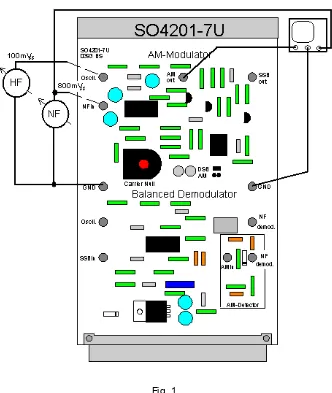
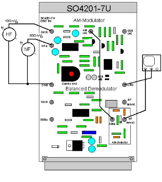
Set up the workplace in accordance with the illustration above. For orientation on the two printed circuit boards use the illustrations under "Control Elements & Sockets".
Put the printed circuit board SO4201/7L "Colpitts/Hartley oscillator" in the left experimenter and the board SO4201/7U "AM modulator/demodulator" in the right experimenter. The required operating voltages on the experimental printed circuit board are automatically connected when the power supply of the UniTr@in I interface is switched on.
The board SO4201/7L "Colpitts/Hartley oscillator" is used in the test on the issue of the amplitude modulation as carrier frequency oscillator for the frequency range of 400...500 kHz. The Colpitts oscillator is used as carrier frequency oscillator.
To do so, plug the jumper plug for the switching of the input signal in the position "HF in / Colpitts" and the jumper plug "X" for the feedback in the circuit of the Colpitts oscillator. As input use the socket "HF out 1:1". Connect this with the input "Oscill" of the board SO4201/7U "AM modulator/demodulator" and use the potentiometer "Tuning 400...500 kHz" and "HF out 0...1" to set a carrier signal with a frequency of 455 kHz (2.2 Cs) and an amplitude of 100 mVpp.
Instruments and Components Required
' % (
1 Interface for UniTr@in SO4203/2A
2 Experimenter SO4203/2B
1 AM modulator / demodulator SO4201/7U
1 Measuring line set 2mm UniTr@in I SO5146/1L
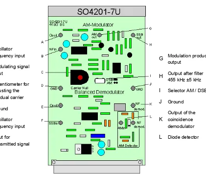
Fig. 2: Top view of the AM modulator/demodulator
G Modulation product output
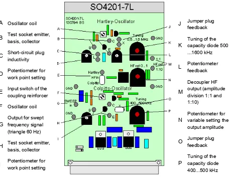
A Oscillator coil
B Test socket emitter, basis, collector
H Test socket emitter, basis, collector
I Potentiometer for work point setting
Fig. 3: Top view of the Colpitts/Hartley oscillator
J Jumper plug
Aims of the Exercise
Aim of the exercise is to show the students the principle of the usual amplitude modulation on the basis of the available test circuit. By examining the amplitude modulation process, the characteristic variables that are typical for this form of modulation will be explained in great depth.
For example the terms carrier oscillation, signal oscillation and degree of modulation will be described.
Theoretical Introduction
The term amplitude modulation is used to define a form of signal modulation where the amplitude of a high frequency carrier signal is varied by a low frequency modulating signal. A basic circuit by a transistor is shown in the picture below.
Mathematically, this process can be considered as a multiplication of the two frequencies. From the two direct frequencies the amplitude modulation generates a frequency mixture with an upper and lower sideband which is situated above and below the carrier frequency to the extent of the modulation frequency. The same result we can also get, when we are using a mixer/module.
The main effective variables in amplitude modulation are the parameters
) % and $ ) %. Another variable is the $ ,
given by the ratio of and .
AM is used in long, medium, and short wave transmissions.
Exercise 1
The Principle of AM
Set the carrier signal at the values
* +,, -./ / * 00 1
Fig. 1
On the oscilloscope, measure the signal at the "AM out" socket of the test circuit and comment on the result.
X = 1 Cs/DIV X/T (A)
Channel A = 500 mV/DIV AC
Channel B = mV/DIV OFF
When a signal is applied to the "Oscill" input of the modulator,...
* 0 -./ 2* +00 1
to the input "NF in" input.
Again, on the oscilloscope, measure the signal at the "AM out" socket. Comment on the measured result.
X = 10 Cs/DIV X/T (A)
Channel A = 100 mV/DIV AC
Channel B = mV/DIV OFF
If only the modulation frequency is applied to the "NF in" input of the modulator,...
Now connect both the sockets "Oscill" and "NF in" with the signal values as used
previously. With the potentiometer "Carrier Null" adjust the signal so that the display shows an undistorted signal (almost fully clockwise).
Sketch the envelope shown on the oscilloscope in the grid on the relevant working sheet. Comment on the measured result.
X = 10 Cs/DIV X/T (B)
Channel A = 500 mV/DIV AC
Channel B = 500 mV/DIV DC
If the AF and HF signals are both applied at the modulator input,...
Exercise 2
Degree of Modulation
Retain the settings that were used in the last part of the previous exercise. Slowly reduce the amplitude of the AF signal and then slowly increase it again.
When the amplitude of the AF is changed, the envelope of the AM signal is changed: A reduction causes the oscillation of the carrier amplitude to become and when the amplitude of the AF is increased, these oscillations become .
What influence do the variations made above have on the degree of modulation?
The measurement of these changes in the carrier amplitude is the of modulation.
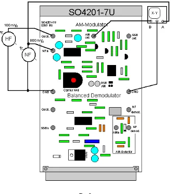
Set the AF signal back to its initial value. Adjust the oscilloscope for the X/Y mode of display. Connect test channel B to the signal at the output of the modulator and test channel A to the AF signal (Fig. 2).
Fig. 2
Modulation trapezium for m<1
X = 10 Cs/DIV X/Y
Channel A = 200 mV/DIV DC
Channel B = 500 mV/DIV AC
If one shows the AM and the AF signal in the X/Y setting with the oscilloscope, a signal is recognisable / the so/called .
Slowly reduce the amplitude of the AF signal to zero. Describe the changes in the X/Y display and compare the result with the changes observed at the input signal as a function of time.
If the amplitude of the AF signals is reduced towards zero, the extent of the trapezium is also reduced to zero in the direction. The sides of the trapezium in the direction change in the opposite direction, whereby the original long side becomes shorter. With an AF signal of 0 volts the beam is only deflected in a direction. In this form of display of the AM along the time axis it is evident that the carrier oscillation is
over time.
Starting with the initial setting, increase the AF amplitude and describe the change in the X/ Y display.
However, if one increases amplitude of the AF, the X deflection is also . Here, also, the parallel sides of the trapezium change in opposite directions, whereby the original long side becomes even .
What is the display for a degree of modulation of approximately 100%? Sketch this result in the grid on the working sheet.
Modulation trapezium for m=1
X = 10 Cs/DIV X/Y
Channel A = 200 mV/DIV DC
Channel B = 500 mV/DIV AC
Now increase amplitude of the AF still further and sketch the overmodulation displayed in the X/Y mode in the form of a graph. Ignore any possible signal distortions in the previous display; these are due to component tolerances of the modulator.
When the AF amplitude is increased even further, an occurs, which is shown on the oscilloscope in the X/Y display as two triangles touching at their points.
Modulation trapezium for m >1
X = 10 Cs/DIV X/Y
Channel A = 200 mV/DIV DC
Channel B = 500 mV/DIV AC
How can the X/Y presentation be used qualitatively? Describe this process mathematically.
The modulation trapezium displayed in the X/Y mode can be used for...
This gives the formula:
Exercise 3
Demodulation of an AM Signal
The downstream capacitor is charged by the first positive half wave of the AM signal via the rectifying diode or transistor. With suitable values for R and C, the time constant of this RC combination is chosen so that the high frequency carrier signal cannot cause any discharging of the capacitor. The capacitor can only discharge during the negative half/ waves of the AM signal. This results in a variation of the carrier amplitude in the rhythm with the AF, and so the output corresponds with the signal oscillation.
Connect the exercise assembly as in the third section of exercise 2 with the HF and AF signal. Please connect the "AM out" socket of the modulator to the "AM in" of the AM detector (Fig. 3).
Fig. 3
Now please use the oscilloscope to measure the signal at the "NF demod" output of the AM detector and comment on the measured values.
Signal at the output of the detector
X = 10 Cs/DIV X/T (A)
Channel A
= 200 mV/DIV AC
Channel B