The aim of the exercise is to demonstrate the process of frequency modulation on the basis of the available test circuit, illustrating in detail the attributes, which are
characteristic for this type of oscillation modulation.
Displaying the oscillogramme for the modulation of the carrier oscillation by a useful signal
Explaining the term "instantaneous frequency" at the modulation signal Recognising the terms "rarefaction regions" and "compression regions" Determining the frequency shift as maximum frequency deviation in the FM signal
Effects of AF amplitude and AF frequency on the FM signal Learning about the modulation index
Establishing connection between AF amplitude and AF frequency and phase shift
Recovery of a modulating signal with the coincidence demodulator integrated on the module
Learning about the principles of FM demodulation
!
"
#$ "
%$
&
#$ "
a signal oscillation which is to be transmitted.
The actual signal oscillation changes parameters of the carrier oscillation $ in the case of the FM the frequency $ and is hence prepared for the transmission.
This form of signal modulation is the object of the available test description.
The FM can be described mathematically as follows:
The frequency of the carrier signal is varied in dependence on the modulating signal.
The ratio of the frequency shift ∆) to modulation frequency ω is termed modulation index.
The frequency shift indicates the maximum frequency deviation for the FM.
!"
"$
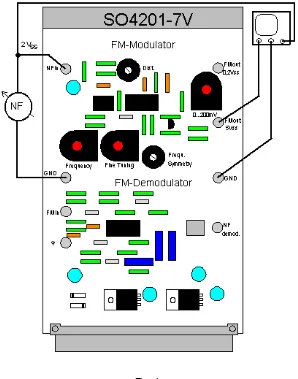
Set up the workplace in accordance with the illustration above. For orientation on the two printed circuit boards use the illustrations under "Control Elements & Sockets".
Put the printed circuit board SO4201$7V "FM modulator/demodulator" in the
experimenter. The required operating voltages on the experimental printed circuit board are automatically connected when the power supply of the UniTr@in I interface is switched on.
Instruments & Components Required
'"&( ! " ( (
1 Interface for UniTr@in SO4203$2A
1 Experimenter SO4203$2B
1 FM modulator/emodulator SO4201$7V
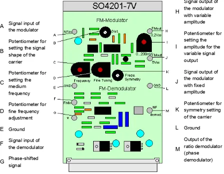
Control Elements & Sockets
Fig. 2: Top view of the FM modulator/demodulator
!
" "
"
Aims of the Exercise
The aim of the exercise is to demonstrate the frequency modulation on the basis of the available test circuit, illustrating in detail the characteristic attributes for this type of oscillation modulation.
Terms such as carrier oscillation, signal oscillation, frequency deviation, phase deviation and bandwidth are examined.
In another exercise the students are intended to present the reverse process, namely the recovery of the modulating signal from a frequency$modulated signal.
Theoretical Introduction
The frequency modulation is understood as the influencing (modulation) of the frequency of a carrier by a modulating signal.
The main effective variables of FM are the amplitude and the frequency of the modulating signal.
With FM the amplitude of the carrier signal remains unchanged.
Where as only an upper and a lower sideband are produced in the case of the amplitude modulation, the analysis of the FM spectrum shows a great number of
The amplitudes of the sidebands of the FM can be determined with the aid of the Bessel functions of the first type, nth order.
Due to the great number of sidebands for the FM – which as far as possible should be transmitted to the greatest possible extent – a relatively broad bandwidth is necessary. For this reason the FM is used in UHF/VHF radio engineering and in radio relay
engineering.
Working Sheet - Test Results
) ! *
! " " "
kHz. The sinusoidal shape of the signals can be exactly balanced with the aid of the potentiometers "Dist." and "Frequ. Symmetry". The potentiometers "Frequency" and "Fine Tuning" now enable you to regulate the frequency from 50 kHz to 150 kHz. This internal frequency is used as carrier signal within the course of further work.
Now set your AF generator to 10 kHz and 2 Vpp. Apply this signal at the input "NF in".
Fig. 1
Use one channel of the oscilloscope to measure the signal at the output of the modulator and the second to measure the AF signal.
X = 10 Js/DIV X/T (B)
Channel A = 2 V/DIV AC
How does the signal at the output of the modulator behave, if there is no signal at the input and if an AF signal is applied at the input of the modulator?
The value of the frequency changes every moment. Therefore it is referred to as the so$
called .
Comment on the results obtained and explain the terms "instantaneous frequency" and "rarefaction and compression regions".
With the above$mentioned frequency variations a constant change takes place between higher frequencies (frequent polarity changes) and lower frequencies (less frequent
polarity changes). Therefore, these conditions are referred to as in
the case of low frequencies and in the case of high frequencies.
The change between these rarefaction and compression regions follows the rhythm of
the frequency.
In a positive half wave of the modulation frequency, there are frequent frequency
changes, and in a negative half wave of the modulation frequency, there are frequent frequency changes in the frequency$modulated signal.
) ! +
, "" - %$ " # . " " ! / %$ & 0 " / # / ! 0 " /
Retain the settings as in the previous exercise, but change the signal shape of the AF generator from sinusoidal to rectangular.
X = 10 Js/DIV X/T (B)
Channel A = 2 V/DIV AC
Channel B = 500 mV/DIV DC
The result in the above case is:
Why is this exercise more suitable for a rectangular AF signal?
A rectangular AF signal is very suitable for the case in hand because...
Change the amplitude of the AF signal by reducing it slowly. How does the signal change at the output of the modulator?
If the amplitude of the modulating signal is reduced,...
Now change the frequency of the AF signal by slowly increasing it. How does the signal change at the output of the modulator?
When the frequency of the AF signal is increased...
What influence do the frequency deviation and the modulation frequency have on the modulation index?
The modulation index is calculated using the formula:
How does the modulation index influence the value of bandwidth necessary for transmitting a frequency$modulated signal?
The bandwidth for transmitting frequency$modulated signals is calculated with the formula:
Therefore, as the modulation index increases...
Comment on the results obtained in the above exercise with regard to the modulation which occurs in practice with voice and music.
In practice, the amplitude of the modulating signal is identical with the volume, and the modulation frequency is a measure of the pitch of a voice or music signal.
This means that for the transmission of louder signals...
ÛHF
ÛNF
ÛFM
)
ω
φ
Dotted line
Connect your oscilloscope to the "FM out 5Vss" output of the module. Use the two potentiometers "Frequency" and "Fine Tuning" to set the frequency to 100 kHz.
Observe the FM$modulated signal with the AF generator switched on and off. What happens to the course of the phase angle?
In doing so use the formula:
With an unmodulated carrier signal...
In the region of compression the increase in the phase curve is and in the region
of rarefaction than with an unmodulated carrier.
Reduce the amplitude of the AF signal to 0.5Vpp. Now observe the output signal of the
modulator and analyse it with regard to its phase.
When the AF amplitude is reduced...
Set the AF amplitude back to 1Vss and increase the AF frequency to 20 kHz.
With the original amplitude setting but with increased AF frequency the increase of the phase angle is...
Discuss the different results in your working sheet. What term is used for the difference in phase with an unmodulated signal?
The largest deviation of the phase angle from the waveform of an unmodulated carrier
is known as .
Why is the phase angle a very important parameter for the frequency modulation in particular?
In FM influences on the amplitude of the frequency$modulated signal have no effect when the input signal to the receiver is limited accordingly. However, influences on the
phase angle disturb the receiver. They cause a corresponding .
What other term is used for the frequency modulation because of their characteristic phase angle?
Since the frequency modulation always influences the phase angle, it is also known as
– just like the phase modulation.
) ! 1
#$ " - 2& / " " " /
Ratio Detector
Foster$Seeley discriminator
The FOSTER$SEELEY DISCRIMINATOR as a special form of Ratio detector is also known as the PHASE$SHIFT DISCRIMINATOR. It uses also double$tuned rf
transformer to convert frequency variations in the received fm signal to amplitude variations. These amplitude variations are then rectified and filtered to provide a dc output voltage. This voltage varies in both amplitude and polarity as the input signal varies in frequency. This form of phase or frequenncy detectors we are using in practice more in control circuits for limiters or the well known AFC. A good exercise is given under "AM Transmission and Reception techniques" in the chapter "Control circuits" Exercise 3.
For the demodulation in our case we are using a modern form of a phase detector in integrated form.
On the printed circuit board SO4201$7V "FM modulator/demodulator" connect the output of the modulator "FM out 5Vss" with the input of the demodulator "FM in" in accordance with Fig. 2. Now set the AF generator to 5 kHz and 2 Vpp. Apply this signal
Fig. 2
Use the oscilloscope to observe the signal at the output of the demodulator (NF demod).
X = 20 Js/DIV X/T (B)
Channel A = 2 V/DIV AC
Channel B = 100 mV/DIV DC
Describe the test results and comment on them.
Explain the working principle of a phase detector. With the setting shown above for your exercise, measure the signal at the socket "φ" of the demodulator in comparison with the signal at the demodulator input.