TRANSMISSION OF AUDIO AND VIDEO SIGNAL USING SQUARE WAVE FREQUENCY MODULATION
DHANIAH BT MOHD SALEH
This report is submitted in partial fulfillment of the award of Bachelor of Electronic Engineering (Wireless Communication) With Honours
Faculty of Electronic and Computer Engineering Universiti Teknikal Malaysia Melaka
“I hereby declare that this report is result of my own effort except for quotes as cited in the references.”
“I hereby declare that I have read this report and in my opinion this report is sufficient in terms of the scope and quality for the award of Bachelor of Electronic
Engineering (Wireless Communication) With Honours”
Signature : ……….
Supervisor‟s Name : MR FAUZI BIN ABD WAHAB
.
This thesis is dedicated to my beloved parents for their sacrifice towards my success and their loving caring throughout my life and personal growth; it is also dedicated to
ACKNOWLEDGEMENT
Alhamdullillah, thanks to Allah s.w.t., I have finally completed my Projek Sarjana Muda for completing my bachelor, by having a fascinating experience, without facing any major problems.
First and foremost, I would like to express my greatest gratitude to my supervisor Mr. Fauzi Bin Abd Wahab, who kindly gave me guidelines in the technical matters related to the project that I have done. I gained a lot of knowledge and useful information from him.
I would also like to convey my thankful to my project partner, Ros Nurul Farehah Bt Salleh who helped me out due to my project development. Her assistance and help throughout this project are highly appreciated. Without her help and encouragement, it would have been difficult for me to carry on completing my project.
ABSTRAK
Transmission of Audio and Video Signal using Square Wave Frequency Modulation merupakan projek penghantaran isyarat audio dan video dengan menggunakan teknik „Square Wave Frequency Modulation‟. Projek ini memerlukan kajian berdasarkan isyarat audio dan video yang dihantar bersama-sama dengan menggunakan kaedah „analogue modulation‟. Nilai „Carrier Frequency‟ (FC) yang
ABSTRACT
Transmission of Audio and Video Signal using Square Wave Frequency Modulation, this project is about transmitting audio and video signal by using square wave modulation technique. This project requires an investigation based on how audio and video can be transmitted together by using an analogue modulation method. Suitable Carrier Frequency (FC) is determined and developed in order to
CONTENTS
CHAPTER TITLE PAGE
PROJECT TITLE
REPORT VERIFICATION STATUS FORM DECLARATION SUPERVISOR DECLARATION DEDICATION ACKNOWLEDGEMENT ABSTRAK ABSTRACT
TABLE OF CONTENTS LIST OF TABLES LIST OF FIGURES LIST OF APPENDICES
i ii iii iv v vi vii viii ix xi xii xiv I. INTRODUCTION
1.1 Project Introduction 1.2 Objectives
1.3 Problem Statement 1.4 Scopes of Works
II. LITERATURE REVIEW
2.1 Basic Telecommunication System 2.2 Analogue Signal
2.3 Frequency Modulation
2.4 Square Wave Frequency Modulation 2.5 Schmitt Trigger
2.6 Optical Fiber
2.6.1 Optical Audio Video Transmission 2.6.2 Fiber Optic Cable
2.6.3 Signal Source and Detector 2.7 Oscillator 7 9 11 15 19 22 23 25 27 30
III. PROJECT METHODOLOGY
3.1 Research Methodology 3.2 Flow Chart
3.3 Gantt Chart
31 33 35
IV. RESULT AND DISCUSSION
4.1 Modulator Circuit 4.2 Schmitt Trigger Circuit 4.3 Optical Coupler Circuit 4.4 Discussion
37 43 47 51
V. CONCLUSION AND SUGGESTION
5.1 Conclusion 5.2 Recommendation
53 56
LIST OF TABLES
NO DESCRIPTION PAGES
Table 2.1 Comparison between LEDs and Laser 29 Table 4.1 Result Analysis for Modulator Circuit 41 Table 4.2 Result Analysis for Schmitt Trigger Circuit 45 Table 4.3 Result Analysis for Optical Coupler 49
LIST OF FIGURES
NO DESCRIPTION PAGES
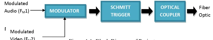
Figure 1.1 Block Diagram of Project 2
Figure 2.1 Basic Telecommunication System 8 Figure 2.2 Analogue and Digital Signal 9
Figure 2.3 Analogue Vs Digital 10
Figure 2.4 Frequency Modulation and Modulated Wave 11 Figure 2.5 Frequency Modulating Signal 13 Figure 2.6 Frequency Spectra of FM Waves 14 Figure 2.7 Modulation Standard for High Frequency Illustration 14
Figure 2.8 Output Signals 15
Figure 2.9 SWFM System 17
Figure 2.10 SWFM Signals 18
Figure 2.11 Schmitt Trigger 20
Figure 2.12 Generic Schematic Schmitt Trigger Circuit 20
Figure 2.13 Schmitt Trigger Output 21
Figure 2.14 Fiber Optic Cable 22
Figure 2.15 Fiber Optic Operation 24
Figure 2.16 Types of Fiber Optic 26 Figure 2.17 Cross Section of Fiber Optic 26 Figure 2.18 Electrical to Light Conversion 27
Figure 2.19 Single Mode Radiating 28
Figure 2.21 Signal Propagate in Fiber Cable 28
Figure 3.1 Flow Chart 34
Figure 4.1 Audio and Video Modulator Circuit 37
Figure 4.2 Input Audio and Video 38
Figure 4.3 10% Resistance 39
Figure 4.4 60% Resistance 39
Figure 4.5 100% Resistance 40
Figure 4.6 Schmitt Trigger Circuit 43
Figure 4.7 Output Schmitt Trigger Circuit for 1 KHz 44 Figure 4.8 Output Schmitt Trigger Circuit for 10 KHz 44
Figure 4.9 Optical Coupler Circuit 47
LIST OF APPENDICES
NO DESCRIPTION PAGES
Appendix A Project Design 58
Appendix B 2N4124 63
LM 358 69
CHAPTER I
INTRODUCTION
1.1Project Introduction
Transmission of Audio and Video Signal using Square Wave Frequency Modulation is a project that involves on research and analysis based on transmitting audio and video signal via fiber optic by using Square Wave Frequency Modulation. Suitable circuits are used to help the modulated audio and video to be transmitted over the optical fiber. This audio and video transmission could be used as an implementation and upgraded version for Close Circuit Television (CCTV).
Basically this project consists of 3 major blocks which are Modulator Circuit, Schmitt Trigger Circuit and Optical Coupler Circuit. The video and audio signal will be modulated to become Frequency Modulation (FM) then both of the signals will be converted to Square Wave Frequency Modulation (SWFM). The used of square wave signal is because it is highly better performance rather than sinusoidal wave signal.
The Schmitt Trigger Circuit is used as a sine to square wave converter and modulates both video and audio signal separately from the original form before being transmitted. These two signals will be transmitted over a fiber optic cable as transmission medium instead of using copper cable which more slightly high distortion and losses.
MODULATOR
Figure 1.1: Block Diagram of Project Modulated
Audio (FM1)
Fiber Optic OPTICAL COUPLER SCHMITT TRIGGER MODULATOR Modulated Video (FM2)
1.2Objectives Project
There are a few objectives to be studied and achieved throughout this project.
1. To develop a suitable Carrier Frequency (FC) for transmitting audio and video
signal since FC is the most important frequency that needs to transmit
together with audio and video.
2. To study and analyze how to modulate audio and video signal using the frequency modulator before both of the signal is modulated together.
3. To design a suitable Schmitt Trigger Circuit need to be constructed for converting FM signal to SWFM.
4. To transmit audio and video signal in SWFM by designing an optical coupler to convert signal in electrical form.
5. To use fiber optic cable as a transmission medium to transmit audio and video signal, since fiber optic is the best medium compared to copper and coaxial cable.
1.3Problem Statement
Currently, Close Circuit Television (CCTV) only provide user video display without audio as its output, thus this project develop the function to display video together with audio signal. In order to transfer video signal together with audio, Frequency Modulation (FM) is used in this transmission thus it is more convenient and has immune variations due to optical losses than Amplitude Modulation (AM).
There are two modulation methods used in analogue modulation in order to transmit the signal, which are Amplitude Modulation (AM) and Frequency Modulation (FM). The used of these two method is depends on the application used. Sinusoidal wave is difficult to analyse compared to square wave since it have a value along the time travel where transmission signal is slightly easy to be analyzed because it is a periodic signal.[4][7]
Signal for transmission can be either be analogue or in digital. Analogue signal is a signal that can be varied continuously with the respect to the information. Analogue communication systems is an inexpensively communication in a band limited that connects from one location to another. For an analogue signal, the signal is varied continuously with respect to the information has the potential for an infinite amount of signal resolution. Compared to digital signals, analogue signals are of higher density and their processing may be achieved simpler than with the digital equivalent and the signal may be processed directly by analogue components.[2]
The used of copper cable for transmitting signal has its own disadvantages which the undesired phase shift can chrome information in long the transmission line. The possibility of ground loop and reflection can be resulted from improper termination of coaxial distribution system.
1.4Scope of Works
The scope of this project is covered on the operation of Square Wave Frequency Modulation (SWFM). This research and analysis is focusing on the basic digital systems that have to be developed by comparing the signal to the common sinusoidal signal. The modulation techniques must be analyzed based on SWFM. Further understanding on how to transmit audio and video signal in SWFM is important to identify the type of modulation technique and system needed in this project.
Suitable circuit is designed as an implementation to transmit audio and video signal using SWFM basis. The circuit basically consists of 3 major parts which are Modulator, Smith Trigger and Optical Coupler. These 3 parts must be fully analyzed in order to transmit a clear and smooth SWFM signal. Circuit simulation is used to ensure the operational of the designed circuit. All the circuit will be simulated and troubleshoot for any unwanted results. All the design circuit can be altered through this simulation process before it be assembled.
The designed circuits are assembled in practically to be tested and troubleshoot if there is any error. The assemble process is very important to identify the output display of the design. PCB Schematic design is converted to PCB layout so that etching process can be made. The PCB design is important where it has to place the component correctly in order to produce a same output as in assembled process.
1.5Project Methodology
There are a few phases for completing this project, which are:
Phase 1: Project Planning
Identify a suitable project title and discussion with a supervisor. Prepare a Gantt chart for the whole project progress as a guideline to be on track.
Phase 2: Literature Review
Background studies based on the project title chosen, and research on suitable circuit needed in the project.
Phase 3: Simulation
Based on the suitable circuit design, simulate the circuits to find out the simulated result need to be achieved by using appropriate software.
Phase 4: Hardware Construction
Identify and specify the components and parts need in the circuit assembly. Designing a circuit boards and assembles. Testing, analyzing and diagnose the circuits.
Phase 5: Finishing
Test the prototype operation, application and results. Prepare project presentation.
CHAPTER II
LITERATURE REVIEW
2.1 Basic Telecommunication System
The basic model of telecommunication data transmission, which is called a point-to-point work, has three main components of a communication system which are transmitter, transmission medium and receiver. The work of a communication system is to transfer information and messages from one place to another. The information received from the information source can be in various forms such as speech of a person is in the form of sound waves, while the pictorial information is in the form of light waves. [5]
2.2 Analogue Signal
An analogue signal is any continuous signal for which the time varying feature of the signal is a representation of some other time varying quantity. It differs from a digital signal in terms of small fluctuations in the signal which are meaningful. This signal uses some property of the medium to convey the signal's information often measured response to changes in physical phenomena, such as sound, light, temperature, position, or pressure, and is achieved using a transducer.[2][6]
In sound recording, fluctuations in air pressure or sound, strike the diaphragm of a microphone which induces corresponding fluctuations in the current produced by a coil in an electromagnetic microphone, or the voltage produced by a condenser microphone. The voltage or the current is said to be an analogue of the sound. Figure below shows the signal for analogue and digital, which red line represent digital signal while grey represent analogue signal.[8]
Figure 2.2: Analogue and Digital Signal [source: http://h20000.www2.hp.com]
An analogue signal has a theoretically infinite resolution. In practice, an analogue signal is subject to noise and a finite slew rate. Therefore, analogue systems are subject to limitations in resolution and bandwidth. Analogue systems become more complex, effects such as non-linearity and noise ultimately degrade analogue resolution to such an extent that the performance of digital systems may surpass it. Similarly, as digital systems become more complex, errors can occur in the digital data stream. A comparable performing digital system is more complex and requires more bandwidth than its analogue counterpart.[1][2]
Figure 2.3: Analogue Vs Digital [source: http://classes.maxwell.syr.edu]
The main advantage is the fine definition of the analogue signal which has the potential for an infinite amount of signal resolution. Compared to digital signals, analogue signals are of higher density. Another advantage with analogue signals is that their processing may be achieved more simply than with the digital equivalent. An analogue signal may be processed directly by analogue components though some processes aren't available except in digital form.
![Figure 2.2: Analogue and Digital Signal [source: http://h20000.www2.hp.com]](https://thumb-ap.123doks.com/thumbv2/123dok/580501.68986/23.595.118.502.401.632/figure-analogue-and-digital-signal-source-http-www.webp)
![Figure 2.3: Analogue Vs Digital [source: http://classes.maxwell.syr.edu]](https://thumb-ap.123doks.com/thumbv2/123dok/580501.68986/24.595.137.528.269.530/figure-analogue-vs-digital-source-http-classes-maxwell.webp)
