TRANSMISSION OF AUDIO AND VIDEO SIGNAL USING SQUARE WAVE FREQUENCY MODULATION
AHMAD SYAFUAN BIN SULAIMAN
This report is submitted in partial fulfillment of the requirements for the award of Bachelor of Electronic Engineering (Telecommunication Electronics) With Honours
Faculty of Electronic and Computer Engineering Universiti Teknikal Malaysia Melaka
UNIVERSTI TEKNIKAL MALAYSIA MELAKA
FAKULTI KEJURUTERAAN ELEKTRONIK DAN KEJURUTERAAN KOMPUTER
BORANG PENGESAHAN STATUS LAPORAN PROJEK SARJANA MUDA II
Tajuk Projek : TRANSMISSION OF AUDIO AND VIDEO SIGNAL
USING SQUARE WAVE FREQUENCY MODULATION
Sesi
Pengajian : 2008/2009
Saya AHMAD SYAFUAN BIN SULAIMAN mengaku membenarkan Laporan Projek Sarjana Muda ini disimpan di Perpustakaan dengan syarat-syarat kegunaan seperti berikut:
1. Laporan adalah hakmilik Universiti Teknikal Malaysia Melaka.
2. Perpustakaan dibenarkan membuat salinan untuk tujuan pengajian sahaja.
3. Perpustakaan dibenarkan membuat salinan laporan ini sebagai bahan pertukaran antara institusi
pengajian tinggi.
4. Sila tandakan ( √ ) :
SULIT*
(Mengandungi maklumat yang berdarjah keselamatan atau kepentingan Malaysia seperti yang termaktub di dalam AKTA RAHSIA RASMI 1972)
TERHAD* (Mengandungi maklumat terhad yang telah ditentukan oleh
organisasi/badan di mana penyelidikan dijalankan)
TIDAK TERHAD
Disahkan oleh:
__________________________ ___________________________________ (TANDATANGAN PENULIS) (COP DAN TANDATANGAN PENYELIA)
Alamat Tetap: 14, HALA PEGOH 1, TAMAN SRI PENGKALAN, 31650 IPOH, PERAK
iii
“I hereby declare that this report is the result of my own work except for quotes as cited
in the references.”
Signature :
iv
“I hereby declare that I have read this report and in my opinion this report is sufficient in
terms of the scope and quality for the award of Bachelor of Electronic Engineering (Telecommunication Electronics) With Honours.”
Signature :
Supervisor’s Name : MR. FAUZI BIN ABDUL WAHAB
v
ACKNOWLEDGEMENT
First and foremost, I would like to thank to Allah S.W.T. for helping me through all the obstacles that I faced during the work of this project.
I wish to express my sincere gratitude to my supervisor, Mr. Fauzi Bin Abdul Wahab, lecturer in the Telecommunication Electronics Engineering Department, Universiti Teknikal Malaysia Melaka for the guidance throughout this project. Thank you for the help, support, motivation and advice.
To dear friends; Mohd Nazreen Bin Abdul Majid and Mashitah Binti Ramli, thank you all for lending hands during the progress of the project. Your contributions are highly appreciated.
vi
ABSTRACT
vii
ABSTRAK
viii
TABLE OF CONTENTS
CHAPTER TITLE PAGE
PROJECT TITLE i
REPORT STATUS FORM ii
STUDENT DECLARATION iii
SUPERVISOR DECLARATION iv
ACKNOWLEDGEMENT v
ABSTRACT vi
ABSTRAK vii
TABLE OF CONTENTS viii
LIST OF TABLES xi
LIST OF FIGURES xii
LIST OF ABBREVIATIONS xiv
LIST OF APPENDIXES xv
I INTRODUCTION 1
1.1 Project Introduction 2
1.2 Project Objective 2
1.3 Problem Statement 3
1.4 Scope of Work 3
ix
II LITERATURE REVIEW 5
2.1 Basic Telecommunication System 6
2.2 Analogue and Digital Signals 7
2.2.1 Frequency and Bandwidth 8
2.3 Video Technologies 10
2.3.1 Bandwidth versus Video Resolution 11
2.3.2 Visual Resolution 13
2.4 Modulation 15
2.4.1 Frequency Modulation 15
2.4.2 Amplitude Modulation 17
2.5 Oscillator 18
2.5.1 Hartley Oscillator 21
2.5.2 Voltage-Controlled Oscillator (VCO) 23
2.6 Operational Amplifiers 23
2.7 Square Wave Converter 23
2.7.1 Schmitt Trigger 24
2.8 Multiplexing 25
2.8.1 Multiplexer 25
2.9 Types of Fibre 25
2.9.1 Optical Source 26
2.9.2 Optical Detector 28
2.9.3 Fibre Measurement 29
2.9.4 Optical Fibre Communication 30
2.10 Project Design 31
2.10.1 Video and Audio Signals 31
2.10.2 Low Pass Filter 32
2.10.3 IC SN74S124N VCO Oscillator 33
x
III PROJECT METHODOLOGY 35
3.1 Phase of Methodology 36
3.2 Project Flow Chart 37
3.3 Project Gantt Chart 38
3.4 Project’s Flow 39
IV RESULT & DISCUSSION 40
4.1 Circuit Diagram 41
4.2 Circuit Discussion 42
4.3 Circuit Schematic using Multisim 43
4.4 Circuit Schematic using Proteus 7 Professional 45
4.5 Simulation using Multisim 47
4.6 Calculation from Multisim 48
V CONCLUSION & RECOMMENDATION 49
5.1 Conclusion 49
5.2 Recommendation 50
REFERENCES 51
xi
LIST OF TABLES
NO TITLE PAGE
2.1 Performance Requirements for Various Video Standards 14
2.2 Reactance Element 19
2.3 Comparison of PIN and APD 27
3.1 Gantt Chart 36
4.1 Output Graph of Simulation 47
xii
LIST OF FIGURES
NO TITLE PAGE
1.1 Block Diagram of Project 4
2.1 Block Diagram of Telecommunication System 6
2.2 Analogue Signal 7
2.3 Digital Signal 7
2.4 Low-Pass Filter 8
2.5 High-Pass Filter 9
2.6 Bandpass Filter 9
2.7 Notch Filter 9
2.8 Modulating Signal Superimposed On the Carrier Wave 15
2.9 Resulting Frequency-Modulated Signal 16
2.10 Amplitude Modulation Signal 18
2.11 Basic Block Diagram of Oscillator 19
2.12 Basic Configuration of Resonant Circuit Oscillator 20
2.13 AC Equivalent of Hartley Oscillator 21
2.14 Hartley Oscillator Circuit 22
2.15 Schmitt Trigger Symbol 24
2.16 Comparator Implementation 24
2.17 HFBR-1524Z LED Source 27
2.18 Low Pass Filter RC Network 32
xiii
2.20 IC LM358N Pin Configuration 34
3.1 Flow Chart Progress of Project 37
3.2 Testing Continuity of the Circuit 39
4.1 FM Pre-Modulation Circuit 41
4.2 Circuit Diagram of Video Amplifier, Square-Wave VCO & E/O Converter 41
4.3 FM Pre-Modulation 7 MHz Multisim Circuit 43
4.4 Video Amplifier & Low Pass Filter 4.2 MHz Multisim Circuit 43
4.5 E/O Converter Multisim Circuit 44
xiv
LIST OF ABBREVIATIONS
AM - Amplitude Modulation
EMI - Electromagnetic Interference FDM - Frequency Division Multiplexing
FM - Frequency Modulation
IC - Integrated Circuit
MUX - Multiplexer
NTSC - National Television System Committee PAL - Phase Alternating Line
PM - Phase Modulation
SECAM - Sequential Color with Memory SWFM - Square Wave Frequency Modulation TDM - Time Division Multiplexing
xv
LIST OF APPENDIXES
NO TITLE PAGE
A List of 7400 Series ICs That Contain Schmitt Trigger 52 B List of 7400 Series ICs That Contain Multiplexer 53
C Circuit Layout 54
CHAPTER I
INTRODUCTION
2
1.1 Project Introduction
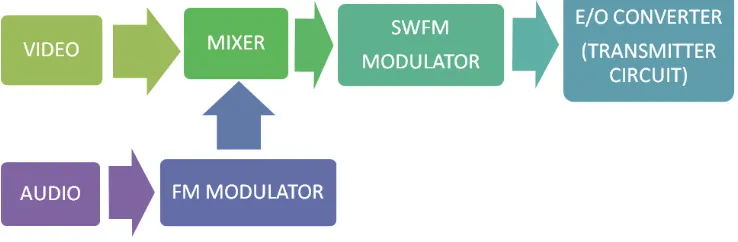
The purpose of this project is to design a system for optical fibre transmission of audio and video signal. Transmission of analogue signal competes with, or even excels the performance of digital system in some cases. Besides that, analogue system is attractive because of the simplicity and lower costs.
The audio and video signal is modulate using square wave frequency modulation (SWFM) technique. The modulated signal is transmit in a safe and efficient way over an optical fibre cable as the physical medium of transmission. The performance will be monitored by using computer simulation and building the hardware.
1.2 Project Objective
The main objectives that should be achieved at the end of this project are:
(a) To design system for optical fibre transmission of audio and video signal. (b) To modulate square wave frequency modulation (SWFM).
3
1.3 Problem Statement
Transmission audio and video signal using copper cable has many disadvantages. There is undesired phase shift which can distort chrome information in long transmission lines. Possibility of ground loops and reflections can be result from improper termination of coaxial distribution systems.
Signal quality degradation is usually caused by inferior electromagnetic interference (EMI) of metal wire cable lines. EMI is electromagnetic energy that causes undesirable responses, degradation, or complete system failure.
Besides that, there is problem about the transmitted signal. Sinusoidal waveform is difficult to analyze because it have value along the travel time where as signal transmission using square wave is easier to analyze because it is a periodic signal.
1.4 Scope of Work
There are several areas that being identified or considered that need to be work out:
(a) Receive audio and video signal from external source: (i) Audio frequency range: 10 Hz – 20 kHz (ii) Video frequency range: 100 Hz – 4.2 MHz (b) Modulate signal into frequency modulation:
(i) Audio and video signal need to modulate separately. (ii) Use oscillator to generate carrier frequency to modulator. (c) Convert sine wave to square wave:
(i) Use Voltage-Controlled Oscillator IC as converter (d) Convert electronic into optical interface.
4
Figure 1.1 Block Diagram of Project
1.5 Methodology
There are five phases involved in order to achieve the objective of this project:
(a) Project Planning
- Identify project and discussion with supervisor
- Prepare Gantt Chart for guidelines and progress of project
(b) Literature Review
- Background studies and references - Searching for suitable circuit
(c) Simulation
- Simulation using Multisim software
(d) Hardware Construction
- Components and parts identification - Designing circuit boards and assembling - Testing, analyzing and diagnose circuits (d) Finishing
CHAPTER II
LITERATURE REVIEW
6
2.1 Basic Telecommunication System
Telecommunication is the transport of information from one place to another. The word has its roots in both Greek (tele) and Latin (communicatio) meaning distant connection. While telephony refers to telephone communications over wire or through the air (wireless), telecommunications today implies the transfer of analogue or digital, voice, video, or data signals over copper wire, wireless, or fibre-optic media.
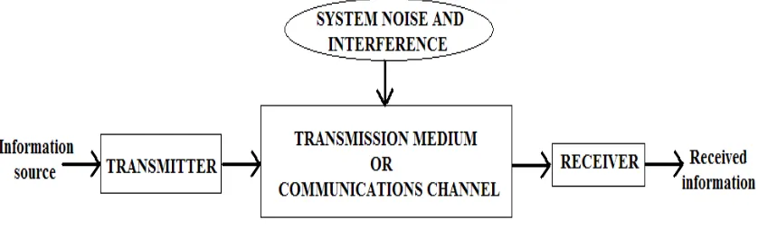
Block diagram of telecommunication system consist transmitter, transmission medium, receiver and system noise. Transmitter is a collection of one or more electronic devices or circuits that converts the original source information to form more suitable for transmission over particular transmission medium. The transmission medium or communications channel provides transporting signals between transmitter and receiver. It can be as simple as pair of copper wires or complex as sophisticated microwave, satellite, or optical fibre communication systems. System noise is unwanted electrical signals that interfere with the information signal. Receiver is collection of electronic devices and circuits that accepts the transmitted signals from the transmission medium and converts those signals back to their original form.
7
2.2 Analogue and Digital Signals
An analogue signal is continuous, such as an electric voltage or current. All values between the maximum and the minimum are allowed. When a voice is converted into an electrical voltage or current, the result is an analogue electrical signal. A digital signal, on the other hand, is discrete in that only certain values are allowed. Most communications signals are now digital. This digital signal uses a binary code (one or zero) to represent discrete values of some original signal or information. The binary code can also be used to represent letters of the alphabet and numbers such as in the ASCII character code. Additional bits for error detection and correction can be added. Using digital signals, any information can be converted to digital form and transport through a communication system.
Figure 2.2 Analogue Signal
8
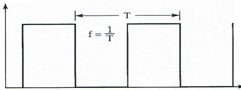
2.2.1 Frequency and Bandwidth
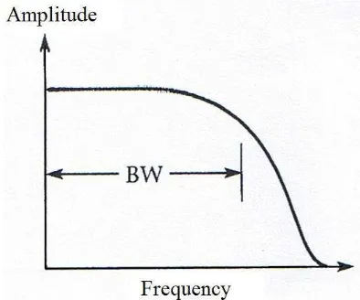
Any time-varying periodic signal can be defined in terms of its frequency, which is the number of cycles per second or equivalently in units of Hertz (Hz). The frequency is also equal to the reciprocal of the period (T). Systems often use filters to control the frequencies to be passed. Filters can allow only lower frequencies (low-pass), higher frequencies (high-pass), or a range of intermediate frequencies (band-pass) to be transmitted. A notch filter passes all frequencies except for a small band.
Bandwidth (BW) used to describe the range of analogue frequencies passed by filter. For digital signals the bit rate is defined as the number of bits transmitted per second (bps). If one bit is sent per digital period, the digital bandwidth is equal to the data rate. Through modulation and multiplexing techniques, often more than one bit can be sent per cycle.
9
[image:24.612.229.427.280.439.2]Figure 2.5 High-Pass Filter
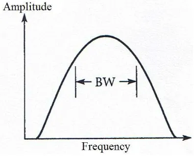
Figure 2.6 Bandpass Filter
[image:24.612.224.431.486.646.2]