RECEPTION OF AUDIO AND VIDEO SIGNAL USING SQUARE WAVE FREQUENCY MODULATION
ROS NURUL FAREHAH BT SALLEH
This report is submitted in partial fulfillment of the award of Bachelor of Electronic Engineering (Wireless Communication) With Honours
Faculty of Electronic and Computer Engineering Universiti Teknikal Malaysia Melaka
UNIVERSTI TEKNIKAL MALAYSIA MELAKA
FAKULTI KEJURUTERAAN ELEKTRONIK DAN KEJURUTERAAN KOMPUTER
BORANG PENGESAHAN STATUS LAPORAN
PROJEK SARJANA MUDA II
Tajuk Projek : RECEPTION OF AUDIO AND VIDEO SIGNAL USING SQUARE WAVE FREQUENCY MODULATION
Sesi
Pengajian : 1 0 / 1 1
Saya ROS NURUL FAREHAH BT SALLEH mengaku membenarkan Laporan Projek Sarjana Muda ini disimpan di Perpustakaan dengan syarat-syarat kegunaan seperti berikut:
1. Laporan adalah hakmilik Universiti Teknikal Malaysia Melaka.
2. Perpustakaan dibenarkan membuat salinan untuk tujuan pengajian sahaja.
3. Perpustakaan dibenarkan membuat salinan laporan ini sebagai bahan pertukaran antara institusi pengajian tinggi.
4. Sila tandakan ( √ ) :
SULIT*
*(Mengandungi maklumat yang berdarjah keselamatan atau kepentingan Malaysia seperti yang termaktub di dalam AKTA RAHSIA RASMI 1972)
TERHAD** **(Mengandungi maklumat terhad yang telah ditentukan oleh organisasi/badan di mana penyelidikan dijalankan)
TIDAK TERHAD
Disahkan oleh:
__________________________ ___________________________________
(TANDATANGAN PENULIS) (COP DAN TANDATANGAN PENYELIA)
“I hereby declare that this report is result of my own effort except for quotes as cited in the references.”
Signature : ……….
Name : ROS NURUL FAREHAH BT SALLEH Date : / /
“I hereby declare that I have read this report and in my opinion this report is sufficient in terms of the scope and quality for the award of Bachelor of Electronic
Engineering
(Wireless Communication) with Honours”
Signature : ……….
Supervisor’s Name : FAUZI B ABD WAHAB
Date : / /
.
This thesis is dedicated to my late father and my mother for their sacrifice towards my success; also dedicated to my supervisor, Mr Fauzi B Abd Wahab, who taught me that even the largest task can
be accomplished if it is done one step at a time.
It may not be enough to contain the words of thanksgiving, it may not capture the endearing love that we have for all of you but now we are making this compilation to let the world know that your
place is a place of love, generosity, and peace.
ACKNOWLEDGEMENT
First and foremost, I would like to express my upmost gratitude and thanks to God, as for His permission, I have completely done this Final Year Project. I would like to grace the highest gratitude to my supervisor Mr. Fauzi B Abd Wahab for his assistance and guidance for me throughout the progress to finish this project. Lots of thanks I should give to Universiti Teknikal Malaysia Melaka (UTeM) for offered this subject where I could benefit my theoretical knowledge and with hands-on practise to complete my project smoothly. I am also greatly indebted to all of my course mates and friends for giving lots of help and suggestion, my friend especially Dhaniah Bt Mohd Saleh for the concern and encouragement in order to make sure this project is on the track and also helping me a lot. And finally, thanks to my mother and my family for their support through pray and financial due to completing this project.
ABSTRACT
The title of this project is Reception of Audio and Video Signal using Square Wave Frequency Modulation (SWFM). This project is referring to the designing of reception of voice and video signal using square frequency modulation. It is intended to receive the signal from transmitter source by using optical fiber system. This device is focusing on the application of PLL demodulation and Square to Sine Oscillator circuit which has their own function to complete this square wave modulation. PLL Demodulation has been chosen because the PLL is an electronic circuit that controls an oscillator so that it maintains a constant phase angle on the frequency of an input, or reference, signal. A PLL ensures that a communication signal is locked on a specific frequency and can also be used to generate, modulate and demodulate a signal and divide a frequency. PLL is used often in wireless communications where the oscillator is usually at the receiver and the input signal is extracted from the signal received from the remote transmitter. This project uses the application of an optical fiber as the transmission medium due to relative newness of the technology. It provides the better system performance, immunity to electrical noise, lower signal attenuation (loss) and resistant to temperature variations and many others.
ABSTRAK
Projek ini adalah untuk membina litar penerima isyarat suara dan video yang menggunakan modulasi frequensi segi empat. Ia berupaya untuk menerima isyarat tersebut daripada sumber penghantar dengan menggunakan sistem fiber optik. Rekaan ini tertumpu kepada aplikasi anjakan dan juga frekuensi sinusoid yang mempunyai frekuensi tersendiri untuk memenuhi modulasi ini. Demodulasi PLL dipilih kerana ianya adalah litar elektronik yang mengawal anjakan jadi ianya menjaga sudut fasa pada masukan frekuensi atau sebagai rujukan, isyarat. PLL bagi memastikan isyarat komunikasi adalah terkunci pada sesetengah frekuensi dan boleh digunakan untuk menjana, modulasi and demodulasi isyarat dan dibahagikan kepada frekuensi. PLL biasanya digunakan pada komunikasi wayarles dimana anjakan biasanya pada penerima dan masukan isyarat dikeluarkan daripada isyrat penerima daripada penghantar kawalan. Projek ini menggunakan aplikasi fiber optik sebagai medium penghantaran berdasarkan kaitannya dengan teknologi terkini. Ia dilengkapi dengan system keupayaan yang baik, ketahanan untuk isyarat gangguan elektrik, kehilangan isyarat yang kecil dan tahan dari variasi suhu dan sebagainya.
CONTENTS
CHAPTER DESCRIPTION PAGE
PROJECT TITLE i
VERIFYING FORM ii DECLARATION iii
SUPERVISOR APPROVAL iv DEDICATION v ACKNOWLEDGEMENT vi
ABSTRACT vii
ABSTRAK viii
CONTENTS ix
LIST OF TABLES xiii
LIST OF FIGURES xiv
I INTRODUCTION
1.1 Application Background 2
1.2 Objectives 3
1.3 Problem statement 3
1.4 Scope of work 4
1.5 Outline of thesis 6
II LITERATURE REVIEW
2.1 Introduction 8
2.2 Modulation 8
2.3 Modulation Method 10
2.4 Demodulator 10
2.5 Demodulation Method 10
2.5.1 Phase Lock Loop 11
2.5.2 Phase Detector 12
2.5.3 Voltage Control Oscillator 13
2.5.4 Filter 14
2.5.4.1 Low Pass Filter 14
2.6 Square Wave Frequency Modulation 15
2.7 Fiber Optic System 17
2.7.1 Introduction 17
2.7.2 Optical Receiver 19
2.7.3 Optical Communication System 20
2.7.4 Optical Loss 21
2.7.5 Connectors 22
2.8 Audio and Video 23
III PROJECT METHODOLOGY
3.1 Introduction 26
3.2 Project Methodology 27
3.2.1 Literature Review 27
3.2.2 Software 27
3.2.3 Hardware Development 27
3.2.4 Measurement process 28
3.3 Flow Chart 29
IV RESULT AND DISCUSSION
4.1 Introduction 31
4.2 Simulation 31
4.2.1 Receiver Circuit - Audio 31 4.2.2 Square to sine oscillator 34
4.2.3 Combination Circuit 37
4.2.4 Receiver Circuit – Video 40
4.2.5 Demodulator – Video 41
4.2.6 Amplifier circuit 42
4.3 Discussion 43
V CONCLUSION AND RECOMMENDATION
5.1 Conclusion 47
5.2 Recommendation 48
REFERENCES 49
LIST OF TABLE
NO TITLE PAGE
4.1 Result analysis for audio receiver circuit 32 4.2 Result analysis of square to sine wave oscillator 35
4.3 Result of the combination circuit 38
4.4 Result analysis for video receiver circuit 40 4.5 Result analysis for demodulator circuit 41 4.6 Result analysis for amplifier circuit 42
LIST OF FIGURE
NO TITLE PAGE
2.1 Angle Modulation 9
2.2 Frequency Modulation 9
2.3 General Basic Phase Lock Loop Model 11
2.4 Ideal Filter Response Curves 15
2.5 Block Diagram of SWFM system 16
2.6 Waveform 17
2.7 Basic Fiber Optic Transmission System 18
2.8 The Basic Communication System 20
2.9 A Generalized Fiber Optic Communication System 21
2.10 Connector Loss Factor 22
2.11 Connector Styles 23
3.1 Block Diagram of the receiver 26
3.2 Flow Chart 29
4.1 Receiver Circuit for Audio 31
4.2 Square to Sine Wave Oscillator circuit 34
4.3 The Combination circuit 37
4.4 The receiver circuit for video 40
4.5 The Demodulator circuit for video 41
4.6 The amplifier circuit for video 42
LIST OF APPENDICES
NO DESCRIPTION PAGES
1 Appendix A 51
2 Appendix B 57
3 Appendix C 66
CHAPTER I
INTRODUCTION
This chapter is about to discuss the project background and overview of the project including application background, objectives, problem statement and scope of project.
1.1 Application background
This project is involves in designing and analysis the voice and video signal using square wave frequency modulation at the receiver part. In communication systems, there are 2 parts which are transmitter part and receiver part. However, this research will cover only the receiver part. The transmitter will send the signal to receiver which means the receiver part will convert the square wave signal to sine wave signal with a suitable circuit.
Currently, there is a fast development of applications requiring the transmission of instrumentation and video signals over short to moderate distances. The application of audio and video project in communication systems that can we see lately are in television, mobile telephone, teleconferencing, remote monitoring, community antenna television (CATV) networks, TV distribution within schools, hospitals and most important the use in closed circuit television (CCTV). CCTV mostly used to monitor the certain area such as banks, airports, military installations, and convenience stores.
Optical fiber transmission is attractive in these circumstances. However we have to choose the correct modulation formats and also have to consider the cost, performance and complexity.
The best option in modulation formats is digital modulation which is it has a good performance and ease of integration within digital networks. However the system is too complex. Analogue intensity modulation offers simplicity, low cost and low bandwidth, but often displays inadequate linearity and low signal to noise ratio.
1.2 Objectives
The purposes of doing this project are:
• To demodulate video and audio signal by using square wave frequency modulation (SWFM) at the reception part.
• To design of an optical fiber reception system for SWFM. • To convert the SWFM to frequency modulation.
• To visualize the video at the LCD as the input.
1.3 Problem Statements
The main goals of this project are to built and assemble the receiver units which are speaker and Liquid Crystal Display (LCD) using the combination of Phase Lock Loop (PLL), amplifier circuit and Square to Sine Wave Oscillator circuit. This project will produce the high quality of the voice and video reception device of the one way communication system. The device has the approximate range of its operation where the transmitter can be separated from speaker approximate at about 1meter but it is depends on the length of the fiber optic cable.
The application of the audio and video becomes the main objective of completing this project. Before that, the study of audio and video characteristic and its operation and must be study furthermore to get the best output. The end of result for this project should be the receiver unit allows users to receive audio and video signal from the audio and video source which are microphone and camera, from certain range from transmitter unit.
The audio and video signal should have the equivalent sound and video quality exactly same of a microphone and camera (original input). This system consists of a modulated stereo and video signal for better sound and video without noise and distortion at the receiver unit.
1.4 Scope of Works
The scope of this project is to design a receiver of audio and video signal using square wave frequency modulation (SWFM). There are several scopes that have been applied to make sure this project can achieve the objectives and function well.
1.4.1 Analyzed and studied about the square wave frequency modulation system and its operation.
This method is focusing on studying the basic operation of square wave frequency modulation and its function.
1.4.2 Modulation and Demodulation Techniques
These techniques are the most important application in the receiver operation which is the transmitter applied the modulation techniques and the receiver applied the demodulation techniques as the main goal on this project.
1.4.3 Application of square to sine wave oscillator
The digital application for this device which is one approach to generating sine waves is to filter a square wave. This leaves only the sine wave fundamental as the output.
1.4.4 Simulate using MULTISIM software
The MULTISIM software has been used to do the simulation of circuit design before fabricate the actual circuit. This is also useful to study the theoretical result for circuit operation.
1.4.5 Design and Simulate Receiver Circuit using PROTEUS 7 Professional Software for PCB Design.
The PROTEUS 7 Professional has been used to do the simulation of circuit design before fabricates the actual circuit. This software also can be used to convert the schematic design to PCB layout.
1.4.6 Construct the receiver circuit of reception compartment.
For this step, the etching technique is the best way to fabricate the circuit schematic. Etching techniques provide best design layout and it simply easier and faster while doing fabrication.
1.5 Outline of thesis
The outlines of the thesis are as follows:
Chapter 1: This chapter provides the introduction to the project, objective and scope of work.
Chapter 2: This chapter covers the literature review on the Square Wave Frequency Modulation, Modulation, Demodulation, and Optical Fiber.
Chapter 3: This chapter covers project methodology used in this project. The flow chart included to make sure that it should be followed for a better performance.
Chapter 4: This chapter provides the results that are obtained from the simulation and also the discussion for this project.
Chapter 5: This chapter gives the conclusion and future work for this project.
CHAPTER II
LITERATURE REVIEW
This chapter will review research that has been done about the project.
2.1 Introduction
The transmission of analog voice and video signals may attractive in small,
short-haul systems. In addition, fiber optic sensor systems may incorporate the analog transmission. Requirements that analog transmission places on applications include high signal to noise ratio and high source linearity. While analog transmission can be attractive for short haul or medium-haul systems, it is unattractive for long-haul systems where digital technique which is square wave frequency modulation (SWFM) provides a better performance. According to this, the main objective is to provide a better size, quality and range of the communication system for devices using SWFM.[1]
2.2 Modulation
Modulation is the process of varying some characteristic of a periodic wave with an external signal. Modulation is utilized to send an information bearing signal over long distances. Radio communication superimposes this information bearing signal onto a carrier signal. These high frequency carrier signals can be transmitted over the air easily and are capable of traveling long distances.
The characteristics (amplitude, frequency, or phase) of the carrier signal are varied in accordance with the information bearing signal. In the field of communication engineering, the information bearing signal is also known as the modulating signal. The modulating signal is a slowly varying signal – as opposed to the rapidly varying carrier frequency.
Frequency modulation Phase Modulation
Figure 2.1 : Angle Modulation ( source: http://www.sciencevault.net)
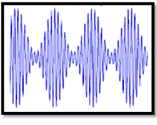
Figure 2.2 : Frequency Modulation (source :
http://www.sciencevault.net)
There are 2 types of modulations: Analog modulation and digital modulation. In analog modulation, it is use to transfer an analog baseband (or lowpass) signal, for example an audio signal or TV signal, over an analog bandpass channel, for example a limited radio frequency band or a cable TV network channel. In digital modulation, an analog carrier signal is modulated by a digital bit stream. Digital modulation methods can be considered as digital-to-analog conversion, and the corresponding demodulation or detection as analog-to-digital conversion. [2]