Comparative Structure Behavior System of Fixed Base and Base Isolation as
Earthquake Result in Irregular Building Configuration
Livian Teddy*1
1
Student Doctoral Program in Architecture and Urban Diponegoro University and Lecturer of the Department of Architecture University of Sriwijaya Palembang
*Email: [email protected]
Abstract
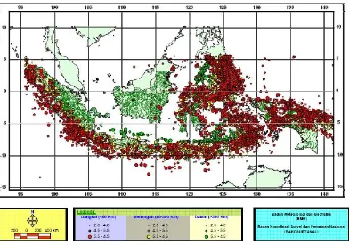
Indonesia is prone to earthquakes because the region is traversed by some of the world's most active seismic lines as the Mediterranean and the Circum-Pacific earthquake belt. Thus has happened thousands of times smaller to large earthquakes that occurred both documented and undocumented. Such conditions should be designed buildings in Indonesia earthquake resistant. One of the basic principles for the design of earthquake resistant buildings is regularity. But in reality is not inevitable either irregular building with functional and subjective reasons. While in designing earthquake-resistant building structures to make the building into a relatively flexible is relatively new compared to the fixed base system structure that is by using base isolation. If the base isolation mounted on irregular building configuration, positive or negative whatever effect on behavior than building structures using fixed base system?
In this study uses quantitative methods to study the type of simulation experiments. Architecture and structures datas used as a model hospital in STAADPRO software then analyzed the numerical results with existing theories.
The research results:
The use of base isolation reduce the base shear force than the fixed base system.
The use of base isolation minimize the drift between floor levels than the fixed base system. The use of base isolation building eccentricity relative increase it than the fixed base system.
Keywords: earthquake, irregular, fixed base, base isolation
1. Introduction
Figure 1. Epicenter Data of the earthquake in Indonesia and surrounding areas
In many earthquake-resistant building regulations, one of the basic principles for the design of earthquake-resistant buildings that regularity. With irregular shapes is not expected to occur eccentricity stiffness center / rotation and the center of mass coincides so that the torque of the building due to the lateral force is relatively no or small. Regular configuration also causes a more equitable distribution of forces to the structural elements such as beams and columns so that the stress concentration on certain structural elements can be avoided. But in reality it is difficult to maintain the configuration of the building in the regular state with functional reasons and subjective. While the design of earthquake resistant structures there are two principles that can be done: first; make the building into a rigid, second; make the building to be relatively flexible.
The principle design of earthquake resistant building structure by making the building to be relatively flexible to follow the direction of motion of the earthquake, is a relatively new (around1980s) compared to rigid structures or better known as seismic isolation. The purpose of this is to reduce seismic isolation seismic inertial forces (demand) rather than increasing the capacity of the building structure (Trevor EK, 2001). Seismic isolation can be placed in the sub structure, upper structure and roof. The position of seismic isolation in sub-structures called base isolation and in this way the more popular done.
If the base isolation mounted on irregular building configuration, positive or negative effect whatever on the behavior of the structure? And this will be studied in this paper with a case study 10 storey private hospital in Palembang which have irregular L-shaped configuration
2. Eccentricity and Torque
center of rotation is a point at the level of the floor when a horizontal load acting on it is not rotating floor level but only translating floors while other levels are not occure horizontal load everything rotation and translation.
Simply put, the center of mass can be said geometrical center of the building so easily calculated quite simply, while the center of stiffness is to calculate the stiffness of the columns and other vertical elements such as shear walls, stairs and so on, so the calculation is quite complicated (Kardiyono, 1997).
Figure 2. Deformation relative floor (Source : T. Paulay dan MJN. Priestley, 1992)
In Figure 2, the effect of eccentricity ex and ey (d) in buildings causes (a). deformation of the x-direction (x'), (b). deformation y-direction (y') and (c). additional rotation and deformation floor x-direction (x'') and y-direction (y''). Deformation and rotation of the above can cause damage to the building.
3. Building Performance
The goal of the performance consisted of the design earthquake magnitude and extent of damage is tolerated or performance level of the building response to the earthquake load. The level of performance is based on the FEMA 273 structures, namely:
Immediately usable (IO = Immediate Occupancy)
Safety occupants guaranteed (LS = Life-Safety)
Figure 3. Illustration of Performance-Based Earthquake Engineering ATC 58
The criteria for acceptance in Planning Performance-Based Earthquake Resistant Buildings are internal forces (moments, shear force, axial force) and deformation (displacement, drift ratio, plastic hinge rotation, permanent deformation) that can be tolerated at a certain level of performance as a result of the earthquake level planned.
Criteria for admission / acceptance criteria can also be applied to all types of seismic analysis of the results of the analysis are elastic (equivalent static, linear-elastic dynamic analysis) and inelastic analysis (static pushover, inelastic dynamic analysis). If the performance of the structure still meet the criteria for the desired level of performance has been achieved (Widodo, 2012).
Acceptance criteria for each performance level can be viewed globally drift Vision 2000.
Tabel 1. Drift global design criteria for each level of performance of the ATC 58
4. Base Isolation
As it is known that the earthquake is hard to control. The intensity of the earthquake in earthquake-resistant design is a demand that must be accommodated by the building structure by increasing the capacity of the building structure. Thus increasing the capacity of the building structure properties (stiffness, strength and ductility) is not easy and not cheap, by making the structure becomes ductile so that when a strong earthquake the building was still able to survive the collapse, despite experiencing inelastic deformation.
The concept of base isolation using a different approach with the above. By reducing demand rather than increasing the capacity properties of building structures so that when a strong earthquake intensity can be reduced and the building still can behave elastic (Trevor EK, 2001).
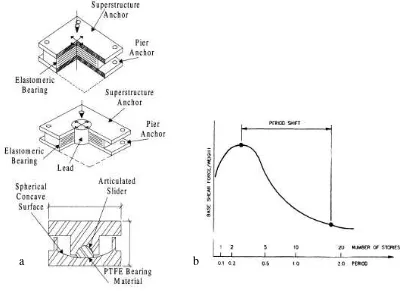
There are 3 fundamental to the practice of seismic isolation system (Ronald LM in Farzad N, 2001), namely:
a b
Damper or energy dissipation tool will work on the relative deflection between the building and the land can be controlled according practical level design.
Still gives rigidity under (service) level loads such as wind and small earthquakes.
Figure 4. a). Seismic isolation tool frequently used. Which on: high dumping rubber, middle: lead rubber, and under: friction pendulum, b). Idealization response style spectrum
(Source : Ronald LM dalam Farzad N, 2001)
There are some similarities to the seismic isolation design with lateral equivalent analysis according to FEMA 450-1 (2003), namely:
TD =
g k
W
MIN
D .
2 ---(1)
DD =
D D D
B T S g
. 4
. . 1
---(2)
Vs =
1
.
R D KDMAX D
---(3)
Keterangan :
KDMIN = Minimum effective stiffness of the isolation system at the design displacement in the horizontal direction under consideration.
KDMAX =Maximum effective stiffness of the isolation system at the design displacement in the horizontal direction under consideration.
g = Acceleration of gravity.
DD =Design displacement at the center of rigidity of the isolation system in the direction under consideration
SD1 = Parameter percepatan spektral disain untuk periode 1 detik
TD = Effective period, in seconds (sec), of seismically isolated structure at the design displacement in the direction under consideration,
BD = Numerical coefficient related to the effective damping of the isolation system at the design displacement, (table 13.3-1 FEMA 450-1, 2003)
Vs = Total lateral seismic design force or shear on elements above the isolation system. R1 = Numerical coefficient related to the type of lateral-force-resisting system above the isolation system. (tabel 4.3-1 FEMA 450-1, 2003).
Total lateral seismic design force or shear on elements above the isolation system (Vs) is distributed to the upper structure by the following formula :
Fx = n Vs
i
1 k i ik x x
.h w .h w
---(4)
Where :
wx, wi = Portion of W that is located at or assigned to level x or i. hx, hi = Height above the base level x or i.
k is a coefficient that depends on the period of the fundamental vibrating structure. The k value is:
k=l if T<0,50 sec. k=2 if T> 2,50 sec.
k is linearly interpolated value when 0.50 <T <2.50 sec.
5. Research Methods and Building Datas
5.1 Research Methods
5.2 Architecture Datas Hospital
Hospital building consists of 10 floors, which consists of semi basement floor and 9 floors above. As each floor functioned as:
semi basement floor : motorcycle parking space, mechanical & electrical and other service spaces.
1stfloor : emergency room and administration manager. 2nd floor: surgery room.
3rd to 8th floor: inpatient unit.
9th floor: meeting room, elevator machine room, water tank.
5.3 Structure Datas Hospital
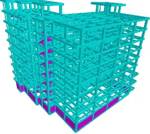
Sub structure used bore pile with 60 cm to a depth varying between 9 to 11 m. While the structure of the type of structure used in this hospital is a rigid frame system concrete beams and columns. While the lateral load resisting system used concrete moment resisting frame system intermediate level. The main structure of the column used dimensionless 60/60 and 40/60. 30/60 beam used while joist vary 30/60, 20/50 and 20/40. Floor plate which is used by 12 cm thick.
Figure 4. 3D structure of the hospital
6. Results and Discussion
6.1 Base shear force
Spectral acceleration values of design parameters for the period from 1 second to Palembang, SD1 = 0.235 g. For building weight (DL + 0.3LL), W = 10077,64 tons and TU-S = 1,58 sec. and TB-T = 1,48 sec. (Livian, 2015). As for the TD value is typically between 0,5T to 1,5T, natural period (T) fixed base = 1,58 sec. so the value of TD = 1,5T = 1,5x1,58 = 2.37 sec. 2, 5 dt. For preliminary is used TD = 2,5 sec. Then look for the effective lateral stiffness of the building with the following formula:
k = 2
k/41 = 41 6482,3
180,3 t/m = 1803 Kn/m.
Of the value of the effective lateral stiffness perkolom sought specification seismic isolation approaching these values, such as the table below:
Tabel 2. Specification Lead Rubber Bearing isolators (LRB) (source : H.H. Lee. et al, 2008)
Total rubber thk. Axial stiffness Lateral effective stiffness
Damping ratio
197,2 mm 4128x103 Kn/m 2.68x10³ Kn/m 30.2
Having obtained the k values of the table above each column recalculated effective lateral stiffness value total:
For design displacement value DD :
DD =
So, total lateral seismic design force or shear on elements above the isolation system (Vs) :
Story Shear (Ton)
0 100 200 300 400 500 Lantai 1
Lantai 2 Lantai 3 Lantai 4 Lantai 5 Lantai 6 Lantai 7 Lantai 8 Lantai 9 Roof
Fixed base U-S Fixed base B-T Base Isolation U-S Base isolation B-T
Figure 5. Comparison of vertical shear force distribution system fixed base and base isolation (source : Analysis)
Likewise, the distribution of shear forces - the base isolation system to the structure above is also reduced (Fig. 5). For a base isolation system, the value of axial and lateral stiffness specifications included as the data support the software STAADPRO and value Vs and TD above as a value control outputs Vs and TD STAADPRO. For other inputs are
relatively similar between the fixed base and base isolation system.
6.2Eccentricity and Torque
The striking differences between regular and irregular buildings configuration are eccentricity. Eccentricity is simply the distance between the center of mass and the center of stiffness. At the distance of a regular building no or relatively small, while in the distance irregular building large enough to pose a potential torque on the building during an earthquake.
The use of base isolation is expected to minimize the distance between the center of mass and stiffness. Based on the analysis STAADPRO output, the use of base isolation is not change the coordinates of the center of mass. So the center of mass at the hospital building systems that use fixed base and the base isolation are equal. What's changed are the center of stiffness. The center of the fixed base system stiffness different from the stiffness center base isolation system.
Eksentrisitas
Koordinat pusat massa & pusat kekakuan
12 14 16 18 20 22 24 26
Pusat massa (x) - fixed base/base isolation Pusat massa (y) - fixed base/base isolation Pusat kekakuan (x) - fixed base Pusat kekakuan (y) - fixed base Pusat kekakuan (x) - base isolation Pusat kekakuan (y) - base isolation
Figure 6. Comparison of the center of mass and center distance stiffness fixed base system and base isolation (source : Analysis)
Figure 7. Comparison eccentricity fixed base and base isolation (source : Analysis)
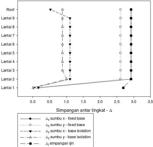
Simpangan antar tingkat -
0.0 0.5 1.0 1.5 2.0 2.5 3.0 3.5
Lantai 1 Lantai 2 Lantai 3 Lantai 4 Lantai 5 Lantai 6 Lantai 7 Lantai 8 Lantai 9 Roof
sumbu x - fixed base sumbu y - fixed base sumbu x - base isolation sumbu y - base isolation simpangan ijin
6.3Building Performance
Hospitals are categorized Critical Facilities and Emergency Facilities that targeted performance which is when an earthquake has not damaged the structure and non-structure are slightly damaged so that it can directly operate after the earthquake. Whereas in the event of a strong earthquake damaged the structure slightly but still there is a safe and non-structural damage can still be improved so that at this level also can be used almost immediately after the earthquake. This means that in case of minor earthquake both structural and non-structural no damage at all.
Building performance level of acceptance criteria by using the global ratio of drift as table 1, to the hospital with a level of operational performance and immediate occupancy whether using a system of fixed base or base isolation is global drift ratio to be achieved <0.5%. To test the performance criteria are achieved by a private hospital if using a fixed base system by comparing the displacement of the roof with building height:
Direction -X axis (North-South)
Roof displacement = 7,873 cm and building height = 37,7 m means the ratio of its global drift = 10.625 / 3770 = 0,0028 = 0,28% <0,5% Ok
Direction -Y axis (West-East)
Roof displacement = 8,821 cm and building height = 37,7 m means the ratio of its global drift = 7,873/3770 = 0,0021 = 0,21% <0,5% Ok
Displacement roof on base isolation system has increased compared to the fixed base system so that the global drift ratio is also increased, both the direction of the x or y axes but all of the standard ratio are still below 0.5%
Figure 8. Comparison of the drift between the level of fixed base & base isolation (Source : analysis)
7. Conclusions and Recommendation
The use of base isolation system as a passive control of the earthquake on the building is relatively new. What's interesting about the use of base isolation is whether the use of base isolation in the building can ignore the basic principles of regularity in designing earthquake-resistant buildings?. From the description above, the use of base isolation can significantly reduce seismic base shear force and the drift between the floor level but because of the configuration of irregular shaped building contained therein eccentricity use of base isolation was able to enlarge the existing eccentricity, which means increased the potential of torque that can damage buildings on during a strong earthquake.
This should be a consideration for architects in designing earthquake resistant buildings. The use of base isolation is not necessarily able to cope with the eccentricity of the building is configured irregular and use of the principle of regularity is needed in designing buildings that use the base isolation.
Reference
BSN, 2002, Standar Perencanaan Ketahanan Gempa Untuk Struktur Bangunan Gedung- SNI 1726 : 2002.
Farzad Naeim (ed.), 2001, The Seismic Design Handbook 2nd Edition, New York : Springer Science+Business Media.
FEMA, 1997, Nehrp Guidelines For The Seismic Rehabilitation Of Buildings-FEMA 273, Washington DC : Federal Emergency Management Agency.
FEMA, 2003, Nehrp Recommended Provision for Seismic Regulation for New Building & Other Structures-FEMA 450-1, Washington DC : Federal Emergency Management Agency.
FEMA, 2012, Seismic Performance Assessment of Buildings-FEMA P-58/ATC 58, Washington DC : Federal Emergency Management Agency.
H.H. Lee. et al, 2008, Evaluation for Dynamic Characteristic fo Base Isolated Residential Building, The 14th World Conference on Earthquake Engineering October 12-17, Beijing, China.
Kardiyono Tjokrodimuljo, 1997, Teknik Gempa, Yogyakarta : Penerbit Nafiri.
Livian Teddy, 2015, Identifikasi Ketahanan Konfigurasi Bangunan Terhadap Gempa (Studi Kasus : Rumah Sakit Swasta 10 Lantai Di Palembang), Laporan Penelitian MKP PDTAP Undip (tidak dipublikasikan).
T. Paulay dan MJN. Priestley, 1992, Seismic Design of Reinforced Concrete and Masonry Buildings, Canada : John Wiley & Sons Inc.
Trevor E Kelly, S.E., 2001, Base Isolation of Structures Design Guidelines, New Zealand : Holmes Consulting Group Ltd.