1
INVESTIGATION OF PHOTOTRIANGULATION ACCURACY WITH USING OF
VARIOUS TECHNIQUES LABORATORY AND FIELD CALIBRATION
A. G. Chibunichev1, V. M. Kurkov1, A. V. Smirnov1, A. V.Govorov1, V. A. Mikhalin2 * 1
Department of photogrammetry, Moscow State University of Geodesy and Cartography, Gorokhovsky 4, Moscow - [email protected]
2
Aerial survey department, Special Technological Center LLC,Gzhatskaya 21/2, St. Petersburg - [email protected]
Commission I, ICWG I/Vb
KEY WORDS: Laboratory calibration, Test-field calibration, Self-calibration, Unmanned aerial vehicles (UAVs), Consumer cameras.
ABSTRACT:
Nowadays, aerial survey technology using aerial systems based on unmanned aerial vehicles (UAVs) becomes more popular. UAVs physically can not carry professional aerocameras. Consumer digital cameras are used instead. Such cameras usually have rolling, lamellar or global shutter. Quite often manufacturers and users of such aerial systems do not use camera calibration. In this case self-calibration techniques are used. However such approach is not confirmed by extensive theoretical and practical research. In this paper we compare results of phototriangulation based on laboratory, test-field or self-calibration.For investigations we use Zaoksky test area as an experimental field provided dense network of target and natural control points. Racurs PHOTOMOD and Agisoft PhotoScan software were used in evaluation. The results of investigations, conclusions and practical recommendations are presented in this article.
Recently becomes widely spread technology of aerial photography using aerial survey of systems based on unmanned aerial vehicles (UAVs) with a variety of digital cameras on Board. It can be "consumer" cameras with curtain-slit shutters, professional - with lamellar valves and devices with a central shutter. Among the producers and users of these aerial systems is often argued that to perform laboratory calibration, because the algorithms of modern digital photogrammetric systems (DPS) have the ability to perform self-calibration during the build process and adjustment of the triangulation. However, comprehensive studies, both theoretical and practical, in this direction was not carried out.
At the Department of photogrammetry of MIIGAiK for many years conducted research of various methods of camera calibration. Below is the example of the research results of different calibration methods for camera Phase One IXU 150 mounted on the UAV Orlan-10.
The results of laboratory and field calibration were compared.
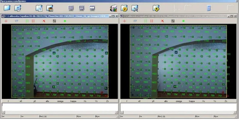
For laboratory calibration was used, the spatial test object and specialized software, developed at the Department of photogrammetry of MIIGAiK. (Fig. 1).
Figure 1. Spatial test-object for laboratory camera calibration
2
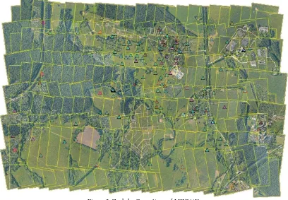
Figure 2. Zaoksky Geopoligon of MIIGAiKFor carrying out field calibrations were used test area “Zaoksky Geopoligon” of MIIGAiK and digital photogrammetric system PHOTOMOD and PhotoScan.
At the site there are over 100 marked control points, and sufficient elevation to calibrate the cameras (Fig. 2).
First results of researches, made on the basis of digital photogrammetric system PHOTOMOD. PHOTOMOD is a universal program that uses classical algorithms for processing of aerial photography. To compensate for the lens distortion here we used two equations. The first equation describes the physical distortion of the lens equation using the classical Braun-Conrad
(1)
where ( , ) – coordinates of the image points, corrected for distortion
( , ) – coordinates of the image points on the original picture
( ) – length of the radius-vector
, , –radial distortion coefficients
, –coefficients of tangential distortion
, – coefficients of expansion and contraction of the image
The same formula is used in classical laboratory calibration chambers at the Department of photogrammetry of MIIGAiK.
The second equation is mixed. Its essence lies in addition to the basic physical formula, an additional few tens of coefficients describing the residual systematic error of the aerial photographs.
(2)
where ( , ) – coordinates of the image points, corrected for distortion
( , ) – coordinates of the points on the original image, in relation to point of symmetry
( ) –length of the radius-vector
, , –radial distortion coefficients
, –coefficients of tangential distortion
... – coefficients of expansion and contraction of the image
The shooting polygon was conducted with two heights of photographing - 600 and 800 m. the pixel size on the ground
3
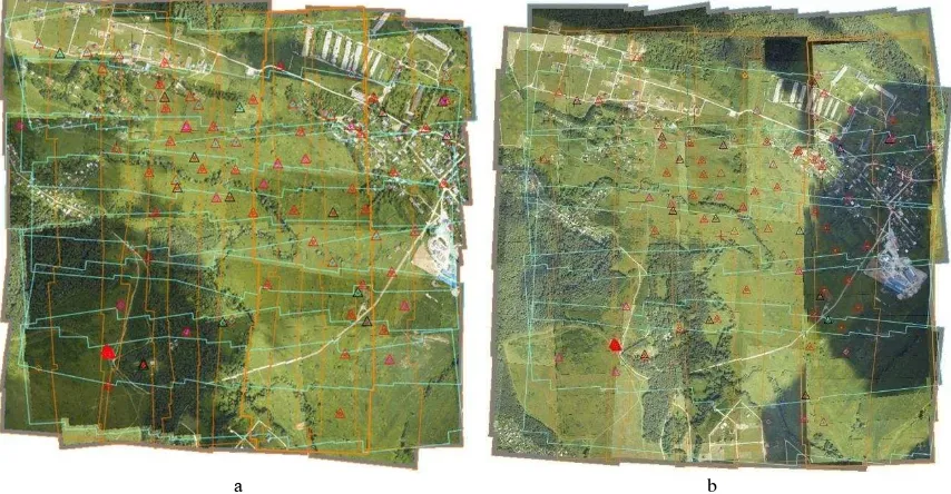
respectively 4 and 6 cm (GSD). Shooting for field calibration,as the routes criss-cross to increase the number of measurements in the pictures. Redundant measurements enable us to obtain more reliable results. In the first case, there was
obtained 327 images (project Polevaya_600), and in the second case, the block consisted of 200 images (project Polevaya_800). All, within the set of images has hit 109 of labeled control points, which were taken for calibration (Fig. 3).
а b
Figure 3. The Diagram of aerial photo: a - height shooting 600 meters; b - height of shooting 800 m
Also performed field-calibration using images obtained with the two heights of photographing (project Polevaya_600-800).
Each block of images was adjusted in several ways: with parameters laboratory calibration, using formulas, physical and hybrid self-calibration.
To estimate the accuracy of different variants of camera calibration was performed two blocks of the photogrammetric
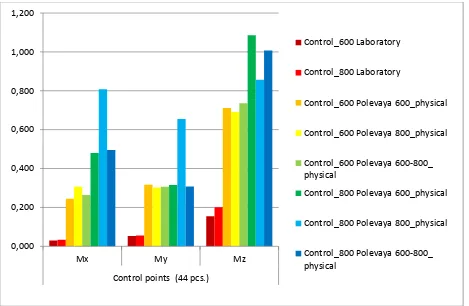
triangulation of images of the polygon, obtained from the heights of 600m and 800m photographing with the same camera. (projects Control_600 and Control_800). Only 5 points were used for control, the other 44 points were used as checkpoints. Of course, self-calibration was not performed in this case. Table 1 shows the results of accuracy estimation of the triangulation executed by PHOTOMOD system, using the various calibration options, and in Fig. 4 and 5 show the corresponding charts.
Projects Calibration by PHOTOMOD GSD
(cm)
Accuracy (in meters)
Control points (5) Check points (44)
Мх М Mz Мх М Mz
Control_600 Laboratory 4.1 0.035 0.025 0.030 0.030 0.053 0.155
Control_800 Laboratory 6 0.013 0.027 0.054 0.034 0.056 0.201
Control_600 Polevaya 600_mixed 4.1 0.025 0.031 0.070 0.046 0.049 0.161
Control_600 Polevaya 800_ mixed 4.1 0.028 0.037 0.088 0.049 0.055 0.171
Control_600 Polevaya 600-800_ mixed 4.1 0.035 0.046 0.094 0.051 0.064 0.188
Control_800 Polevaya 600_ mixed 6 0.021 0.018 0.045 0.038 0.040 0.070
Control_800 Polevaya 800_ mixed 6 0.021 0.015 0.059 0.040 0.040 0.076
4
Control_800 Polevaya 600-800_ mixed 6 0.021 0.013 0.068 0.039 0.041 0.085
Control_600 Polevaya 600_physical 4.1 0.180 0.107 0.139 0.245 0.317 0.712
Control_600 Polevaya 800_physical 4.1 0.204 0.050 0.113 0.306 0.302 0.691
Control_600 Polevaya 600-800_ physical 4.1 0.183 0.087 0.137 0.263 0.306 0.736
Control_800 Polevaya 600_physical 6 0.136 0.135 0.070 0.479 0.316 1.085
Control_800 Polevaya 800_physical 6 0.143 0.164 0.058 0.808 0.655 0.857
Control_800 Polevaya 600-800_ physical 6 0.144 0.146 0.088 0.495 0.308 1.007
Table 1. The results of the accuracy estimation of the triangulation in PHOTOMOD
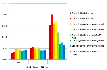
Figure 4. Estimation of accuracy of the triangulation on the basis of results of field calibration. PHOTOMOD (formula mixed distortion)
0,000 0,050 0,100 0,150 0,200 0,250
Мх Му Mz
Control points (44 pcs.)
Control_600 Laboratory
Control_800 Laboratory
Control_600 Polevaya 600_mixed
Control_600 Polevaya 800_ mixed
Control_600 Polevaya 600-800_ mixed
Control_800 Polevaya 600_ mixed
Control_800 Polevaya 800_ mixed
Control_800 Polevaya 600-800_ mixed
5
Figure 5. Estimation of accuracy of the triangulation on the basis of results of field calibration.PHOTOMOD (formula physical distortion)
From the tables and diagrams it can be seen that the best results in terms of accuracy obtained when applying the results of laboratory calibration or when using the results of field camera calibration (formula mixed distortion). In PHOTOMOD system, it is recommended to use a mixed self-calibration, as in this case, the accuracy of the triangulation is better.
The second part of the work was the analysis of the triangulation accuracy in the system Agisoft PhotoScan. This program uses a different model camera calibration, is shown
(cx,cy) – the coordinates of the principal point
K1,K2,K3 – radial distortion coefficients
P1,P2 – coefficients of tangential distortion
skew –coefficient of non-orthogonality of the image coordinate system
The camera calibration parameters were determined on the basis of a phototriangulation with self-calibration for the same sets of images to PHOTOMOD obtained from the photographing elevation of 600 m and 800 m (Fig. 6).
6
Figure 6. The layout of the aerial photoFurther assessment has been carried out the accuracy of the triangulation on the same blocks shots, and in the case of PHOTOMOD, using different versions of the camera calibration parameters.
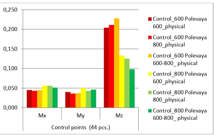
The blocks of pictures were fully identical in both programs with the same number of images, the reference and control points. In Table 2 shows the results of evaluating the accuracy of the triangulation executed in PhotoScan, and in Fig. 7 shows the corresponding chart.
П оек ы Calibration by PhotoScan GSD (
m)
Accuracy (in meters)
Control points (5) Check points (44)
Мх М Mz Мх М Mz
Control_600 Polevaya 600_physical 4.1 0.045 0.042 0.057 0.045 0.040 0.204
Control_600 Polevaya 800_physical 4.1 0.042 0.042 0.033 0.043 0.036 0.211
Control_600 Polevaya 600-800_physical 4.1 0.045 0.042 0.041 0.045 0.037 0.228
Control_800 Polevaya 600_physical 6 0.014 0.020 0.053 0.056 0.050 0.133
Control_800 Polevaya 800_physical 6 0.011 0.016 0.063 0.056 0.043 0.125
Control_800 Polevaya 600-800_physical 6 0.011 0.016 0.055 0.051 0.046 0.098
Table 2. The results of the estimation of the accuracy of the triangulation by PhotoScan
Figure 7. Assessment of accuracy of the triangulation on the basis of results of field calibration. PhotoScan (formula physical distortion)
0,000 0,050 0,100 0,150 0,200 0,250
Мх Му Mz
Control points (44 pcs.)
Control_600 Polevaya 600_physical
Control_600 Polevaya 800_physical
Control_600 Polevaya 600-800_ physical
Control_800 Polevaya 600_physical
Control_800 Polevaya 800_physical
Control_800 Polevaya 600-800_ physical
7
From the tables and diagrams show that the best resultsobtained by application of the results of field calibration at a lower altitude photography and with a smaller pixel size on the ground, which is quite natural. Thus, the accuracy in height is much better at higher altitude photography, which is contrary to the natural laws accuracy of the triangulation. This is because when the photographing height of 600 m. the overlap between the images was approximately 80%, and at an altitude of 800 meters, respectively 70%. At 80% overlap between shots basis photographing of course less than 70%, and hence the angle of the notch is smaller, which leads to the decreased accuracy of the triangulation in height.
CONCLUSIONS:
1. Laboratory camera calibration gives results comparable in accuracy with a field calibration. Thus, it is recommended to perform laboratory calibration of the camera, as this ensures obtaining a satisfactory result on accuracy for the implementation of real projects. The self calibration is performed with the triangulation of real projects can give good results on accuracy. However, there may be cases when self-calibration will not give the desired result but the quality of shooting due to weather and atmospheric conditions and because of work focal-plane shutter and so
on or even the task of self-calibration may not be resolved in the case of flat-flat terrain.
2. It is advisable to perform research each set of hardware and software (unmanned aerial vehicle with a camera and GNSS and DPS to process images) at the site to confirm the manufacturer of characteristics to obtain documents about the area specified accuracy. Such studies are currently being performed in CA MIIGAiK with the appropriate certificate.
REFERENCES:
1. Instruction for photogrammetric processing for creating digital topographic maps and plans. —М.: CNIIGAiK, 2002. - 100 p.
2. The main provisions of the aerial survey performed for creation and updating of topographical maps and plans. / Main department of geodesy and cartography under the USSR Council of Ministers, the Ministry of civil aviation. — М.: Nedra, 1982. - 15 p.
3. Mikhailov A.P., Chibunichev A.G. Lecture notes on photogrammetry. —М.: MIIGAIK, 2012, - 252 p.
4.PHOTOMOD 6.0.2. User’s Guide. —М.: JSC Racurs, - 1605 p.
5. PhotoScan Professional Edition, version 1.2. User’s Guide. —М.: LLC Agisoft, - 116 p.