ACTIVE AND PASSIVE 3D IMAGING TECHNOLOGIES APPLIED TO
WATERLOGGED WOODEN ARTIFACTS FROM SHIPWRECKS
A. Bandiera a*, C. Alfonso b, R. Auriemma b
a
SIBA - Coordinamento Servizi Informatici Bibliotecari di Ateneo, Università del Salento, 73100 Lecce, Italy b
Dipartimento di Beni Culturali, Università del Salento, 73100 Lecce, Italy
Commission V
KEY WORDS: 3D modelling, data processing, waterlogged artefacts, restoration, laser scanning, image-based modelling, photogrammetry
ABSTRACT:
The fragility of organic artefacts in presence of water and their volumetric variation caused by the marine life on or surrounding them dictate that their physical dimensions be measured soon after their extraction from the seabed. In an ideal context, it would be appropriate to preserve and restore all the archaeological elements, rapidly and with the latest methods. Unfortunately however, the large number of artefacts makes the cost of such an operation prohibitive for a public institution. For this reason, digital technologies for documentation, restoration, display and conservation are being considered by many institutions working with limited budgets. In this paper, we illustrate the experience of the University of Salento in 3D imaging technology for waterlogged wooden artefacts from shipwrecks. The interest originates from the need to develop a protocol for documentation and digital restoration of archaeological finds discovered along the coast of Torre S. Sabina (BR) Italy. This work has allowed us to explore recent technologies for 3D acquisitions, both underwater and in the laboratory, as well as methods for data processing. These technologies have permitted us to start defining a protocol to follow for all waterlogged wooden artefacts requiring documentation and restoration.
*
1. THE UNDERWATER SITE 1.1 Wood restoration and 3D documentation
The University of Salento, Italy, has been conducting numerous underwater archaeological surveys along the Ionian and Adriatic coast of Salento. In the last 20 years, 550 isolated finds and 88 wrecks have been uncovered. Many of these sites are composed of organic materials. The different conditions of discovery push archaeologists to find a proper restoration process that guarantees their preservation for a long time. The physical restoration of the finds is necessary to document and record in detail all the dimensional data of the finds from their discovery until the final stage of the restoration. The dimensional changes of a specimen in fact, from the time it is extracted from water until to its preservation in a museum, are not at all insignificant. For instance, wooden specimens once recovered from the seabed would have naturally deteriorated through desiccation, bacterial and fungal decay, and wood-boring organisms if not for appropriate conservation and restoration operations. Even after a first consolidation treatment they still require frequent and continuous monitoring before their final consolidation, i.e., reinforcement or stabilisation. The techniques of wood restoration are expensive and usually irreversible. Therefore, they do not always yield the best results. We considered it necessary to record and document the size and shape of the organic specimens at the "time" of their recovery using 3D digital imaging technology.
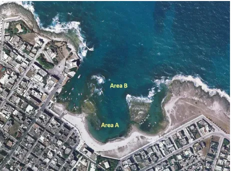
1.2 Bay of Torre Santa Sabina (BR), Italy
The historical reconstruction of the site of the bay of Torre Santa Sabina 25 km north of Brindisi in Italy is based on the
large collection of artefacts that was discovered there. Many of which are intact or complete. The reconstruction allows one to conclude that the site was visited and used from the Bronze Age until the Middle Ages. This information resulting from investigations carried out on the site from the 70s until today attests to the full inclusion of the Salento region in the routes, the network of contacts and exchanges in the Mediterranean (Auriemma, 2004) (see fig.1 for a map). The seabed of the bay preserved remains of cargo ships and hulls, quarry materials and artefacts resulting from port activity (Auriemma, 2014, Auriemma 2011).
Figure 1. Torre. S. Sabina bay (BR), along the Adriatic coast of Salento, Italy
In the inlet, at least five wrecks have been identified and, in particular, the wreck "Torre S. Sabina 1" (see Figure 1- area A) The International Archives of the Photogrammetry, Remote Sensing and Spatial Information Sciences, Volume XL-5/W5, 2015
is a site of great interest, amongst the best preserved Roman ship in the Mediterranean region (Alfonso, 2014). Its study is decisive for both the historical (shipbuilding, cargo, routes, etc.) and the geo-archaeological aspects. The wreck was pulled out of the water in roman era but it seems to have been progressively submerged by a rise in the sea level. Similar considerations apply to the remains of the overlapping cargos of boats that through the centuries were shipwrecked along the rocky escarpment (area B), creating a massive deposit of heterogeneous archaeological materials, often in an excellent state of preservation (Auriemma et al., 2011; Cocchiaro, 1999).
In area B of the bay, at a depth of about 5 m, during the excavation of 2012, some fragments of waterlogged wood were found, interspersed with the cargo pottery. One of which is particularly interesting and it seems to belong to one of the overlapping shipwrecks. The element in question (see fig. 3), though fragmentary, is 110 cm long, 12 cm wide and on average between 6.5 and 10 cm high. Along the edges of the top face, one can see two rows of mortises, staggered (size 6.7 cm x 1.2 cm), 4-6 cm away from each other, with tenons broken inside them. At mid-length there is a circular through-hole (diameter 1 cm), with the lower end eroded by the Teredo navalis (shipworms). A wooden peg is visible at one end of the element and has a diameter similar to the hole described. At approximately 3 cm from this object, the concretion of the head of a round nail appears. As a hypothesis, one could identify the piece with an element of the axial carpentry, maybe a section of the keelson. The almost vertical orientation of the mortises and the small size of the wood is a feature of the artefact.
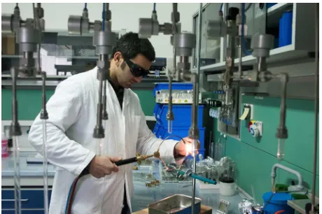
1.3 Radiocarbon dating
Radiocarbon dating performed by CEDAD (Centre for Dating and Diagnostics) at the University of Salento estimated a chronological window of 510-350 BCE (with a probability of 65.4%) and 300-200 BCE (with a 20.8% probability). The samples, before being introduced into the accelerator Tandetron for dating, are subjected to a chemical treatment in the Lab chemicals for Accelerator Mass Spectrometry.
Figure 2. One of the stages of preparation of the wooden samples at CEDAD Laboratory.
1.4 Xylotomous analysis
The xylotomous analysis carried out with the collaboration of the Chair of Materials and Technologies for Restoration of the University of Salento made it possible to establish that the waterlogged wood is of “Quercus Ilex” (Holm Oak) (Colazzo, 2011/2012). The artefact, recovered from the sea, is currently in
a process of desalination at the restoration laboratory of the Department of Cultural Heritage of the same University. In order to better preserve its morphological features from the very moment of its recovery from the sea, the artefact, along with other fragments of smaller sizes, has been immersed in fresh water inside a special tank. The fresh water is changed on a regular basis.
1.5 Experiments and paper structure
In this paper, three experiments performed by the University of Salento in this area of marine archaeology using 3D imaging and processing technology are illustrated with two small artefacts taken from an actual shipwreck and an actual fully immersed shipwreck site. These experiments stem from the need to develop a protocol for 3D documentation and also to test digital restoration techniques on waterlogged wood.
Section 2 explains the motivation for using 3D imaging for preservation and restoration. Section 3 presents the 3D survey methodology used. It is followed by a discussion on the advantages of 3D ‘metric’ imaging for marine archaeology and of determining the time frame within which one can operate, out of water, without the artefact suffering significant morphological changes. Furthermore, the importance of transforming a traditional 2D imaging campaign into an image-based one for 3D modelling is demonstrated with a concrete example. A discussion about the importance of adding 3D technologies to the tool box of marine archaeology and a short summary of our protocol in-progress are reviewed. Concluding remarks complete this paper.
2. PRESERVATION AND RESTORATION OF WATERLOGGED WOOD
2.1 Anoxic environment
The archaeological elements of organic nature that have been submerged for a long time have survived only thanks to the special underwater anoxic environment and hence the waterlogged wood has not deteriorated since it was immediately covered by sediment. They remained in this condition until the archaeological excavation took place. The tunnelling created by shipworms found inside the artefacts assumes short periods of exposure of the wood to the attack of xylophage animals (Beltrame, 1996).
2.2 Aerobic environment
The wooden specimens once recovered from the sea, in the absence of appropriate conservation and restoration operations would face their natural deterioration caused by desiccation, bacterial and fungal decay, and wood boring organisms [Karsten et al., 2012; Petriaggi, 2010; Petriaggi, 2010b; De Troia et al., 2007). Even after a first consolidation treatment they still require frequent and continuous monitoring before their final consolidation, i.e., reinforcement or stabilisation of wooden artefacts. The techniques of wood restoration are expensive and usually irreversible. Therefore, they do not always yield the best results (Boetto, 1999).
2.3 “Just in time” 3D recording
We considered it necessary, in this case, to record and document the size of the organic specimens at the "time" of their recovery using 3D digital imaging technology. Laser The International Archives of the Photogrammetry, Remote Sensing and Spatial Information Sciences, Volume XL-5/W5, 2015
scanner technology provided us with tools to facilitate detailed studies of artefacts without direct contact with the fragile surfaces. Though this was possible in the laboratory, we also explored the use of the more flexible image-based dense stereo methods for on-site underwater documentation.
3. 3D SURVEY: METHODOLOGY AND ANALYSIS OF THE ACQUIRED DATA
Three-dimensional (3D) digital technology applied to the restoration of wooden cultural heritage artefacts is not a new practice [English Heritage, 2011; Guidi et al., 2007), nor is its application to relics found in an underwater excavation [Palma, 2004; Lanave, 2006]. Laser scanners have been used on several occasions to monitor changes of waterlogged materials before and after a treatment [Schindelholz, 2005; Karsten et al., 2010; Cretté et al., 2013). In our case, however, it was necessary to prepare a protocol to be applied to materials requiring immediate restoration.
3.1 Experiments performed in the laboratory
A series of experiments were conducted in a laboratory setting at the University of Salento1 (Bandiera et al., 2013). The first experiment was on a large wooden fragment (probably an element of the axial carpentry) described in Section 1.2 and the Radiocarbon dating is given in Section 1.3. A Minolta ® Vivid 900 laser scanner was used to acquire 3D images of the artefact (see fig. 3). The presence of “noisy” areas and of surface deficiencies in the digital 3D model indicated that the artefact had suffered important dimensional changes throughout the day of the acquisition.
Figure 3. A Minolta ® Vivid 900 was used for the first experiment on a large wooden fragment.
Four tests were carried out to verify the extent of the dimensional variations. The results did not give a clear answer, just a general shrinkage and bulging in certain areas. On average, the deformation varied by a few mm (see fig. 4).
Figure 4. Colour coding showing the dimensional variations between morning and afternoon.
1
Coordinamento SIBA University of Salento, http://siba.unisalento.it/lab_3d, http://siba.unisalento.it/3ddb (accessed 02-2015).
To determine with certainty whether the dimensional changes were caused by the progressive desiccation of the artefact or by a mechanical cause e.g. the handling or crushing of the wood under its own weight, we carried out tests on a smaller sample (approx. 15 cm. in length) that had detached itself from the rest of the main artefact of interest.
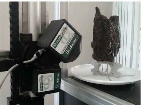
The creation of the 3D models of the sample was performed with a 3D laser scanner from ShapeGrabber ®2 (configuration AI300 + SG102) (see fig. 5). This scanner, suitable for high-resolution acquisitions of small objects, is equipped with a rotating base which allows 3D scans all around individual artefacts in a completely automatic way. This, in turn, minimizes the time in handling these fragile artefacts. InnovMetric Polyworks ® Modeler and Inspector3 were used for 3D image alignment, modelling and data verification.
Figure 5. Test sample positioned on top of a control object and on a rotating stage to automate the 3D scan acquisition phase.
The test sample was weighed at the beginning and at the end of the tests. Its weight was 848 g when it was extracted from the water tank and drained of excess water. It was positioned on a purpose-built support. This support consisted of metallic scaffolding that crossed it in four points. The artefact also rested on a metal object of previously recorded dimensions (see fig. 5). On the first day, five series of scans, at intervals of two hours were performed. Each series consisted of 12 individual scans in automatic mode with a rotation of the base by 28 degrees. In the following days, two scans, at intervals of approximately 6 hours each, were performed. Temperature (average = 25°C±2.5°C) and relative humidity (average = 46%±6%) were constantly monitored but not controlled. The test was concluded eight days after it had begun. The test sample was still wet and weighed now only 264 g. Over a period of 7.5 hours during the first day, the dimensional variations had remained fairly uniform.
The difference between the first and the second overlapping scans is approximately -0.1 mm on the whole surface except for some points. For example the difference is positive (0.1 mm) where the wood had a crack that gradually enlarged. It is interesting to note that the fracture started to accentuate right away. More or less the same values were recorded between scans 2 and 3, 3 and 4, 4 and 5 of the same day. In total, during the first day of scans, the average dimensional variations that the test sample suffered (comparison between the first and fifth
2
http://www.shapegrabber.com (accessed 02-2015) 3
http://www.innovmetric.com (accessed 02-2015) The International Archives of the Photogrammetry, Remote Sensing and Spatial Information Sciences, Volume XL-5/W5, 2015
series of scans) amounted to about -0.6 mm. In some points instead, where they were already clear fractures present, the test sample had positive displacements (fig. 6). These values are consistent with those seen on the larger waterlogged wooden relic and confirmed that in a day, due to the evaporation of water, there was a general decrease in volume, although modest (-0.6 mm) in the proximity to the deep fractures. Instead, there was a progressive "detachment" of a portion of the test sample from its original position by about 2 to 5 mm. The changes that occurred in the following days instead were much greater. It is a freeform object and the distortions are subjected to internal forces within the object that are not isotropic.
Figure 6. Typical dimensional variations that took place over a period of 8 days (each small square measures 1 mm on the side;
tick marks are at every 10 mm).
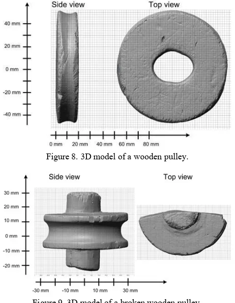
Thanks to this work, we are in a better position to start defining a protocol to follow for all waterlogged wooden artefacts that need to be documented and restored. Starting with a draft protocol, we proceeded with the 3D acquisition and modelling of other wooden elements of shipbuilding nature. A rendering using synthetic shading of a few of them is shown in fig. 7-10.
Figure 7. 3D model of a wooden element.
Figure 8. 3D model of a wooden pulley.
Figure 9. 3D model of a broken wooden pulley.
Figure 10. 3D model of a wooden element.
3.2 Underwater experiment
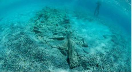
Laser scanner technology provided us with tools to facilitate detailed studies of artefacts without direct contact with the fragile surfaces and especially when those surfaces have very uniform reflectance textures. Though these active systems were adequate in the laboratory or in some outdoor field surveys, underwater use of active 3D scanners requires special systems [Mirallès et al. 2010]. Therefore we explored the use of a more flexible technique, i.e., image-based dense stereo and multi baseline methods for both laboratory use and for underwater documentation (Shortis et al., 2009, Drap et al., 2013). Figure 11 shows a photograph of one of the co-authors of this paper while documenting the site of interest.
Figure 11. Underwater excavation and documentation of the hull (foto G. Piccioli).
Many recent publications present solutions for the automatic generation of textured dense 3D surface models from 2D images in a single or multiple baseline arrangements. Commercial, low cost software packages and open source solutions, including web services, have become very popular (Remondino et al., 2012). A commercial software package was selected for this experiment and public domain software CloudCompareV24 was used for scaling purposes. Agisoft® PhotoScan5 is a commercial image-based 3D modelling solution aimed at creating 3D content from still images. It is based on multi-view 3D reconstruction technology and works with arbitrary oriented images. Image alignment, 3D model reconstruction and texture mapping are fully automated and they necessitate very little user intervention.
The opportunity arose thanks to a recent discovery in the eastern Ionian coast of Italy. The wreck, reported in 2009 by a local diving team6, was found in the waters of Porto Cesareo (LE) between Torre Lapillo and Torre Chianca, only 2 m underwater and just 50 m from the coast. It took its name from the seaside resort where it was found (wreck of the Bacino Grande). Almost certainly it was a midsize boat abandoned to the breakers probably after beaching, as can be deduced from its position: parallel to the shoreline as happens, and has been seen for many other beached wrecks along the Salento coast. It is oriented 330° N with what appears to be the bow and occupies an area measuring approximately 8 m × 3.5 m. The wreck is subject to continuous seasonal silting that has allowed its preservation until today. It is now considered as an important archaeological marker for the reconstruction of ancient paleo landscapes and the determination of the relative sea level changes.
From a first reconstruction of the dynamics of the shipwreck, it appears that the wreck was beached and, upon impact with the bottom, it tilted onto its starboard side. This would explain why only half (lengthwise) of the wreck is preserved. The weight of the stone ballast anchored the wreck to the seabed, which created an anoxic environment that probably allowed it to be kept in good conditions and gave the wood a very clear colour.
Sasa Diving by Gubello Salvatore.
Figure 12. Wreck from the Bacino Grande at a 2 m depth at Porto Cesareo (LE-IT) between Torre Lapillo and Torre
Chianca.
Radiocarbon dating performed by CEDAD (Centre for Dating and Diagnostics) at the University of Salento estimated a chronological window of 770-1030 CE with a reliability of 95.4%.
In 2014, a stratigraphic excavation was performed, bringing to light more details of the whole wreck. The intensive excavation operations lasted less than a week. A photogrammetric survey was quickly performed since, during the period of excavation, the weather conditions were variable and the hull was considerably affected by waves (of small intensity), given also the shallow depth of the water. To attenuate the intensity of the waves, an underwater artificial barrier made up of sandbags was built.
During the excavation phase all the fine sediments were suctioned with a special water pump, to make the hull with its ballast visible. This allowed us to evaluate the status quo of the wreck after the shipwreck and to make a detailed 2D photomosaic, before and after the ballast removal and the complete hull cleaning. This was done by taking zenithal photographs, at water level. For the 3D survey, the photographs were taken in a systematic way by using a non-metric camera inside an Ikelite diving housing7. A shooting plan was followed in order to minimize the time spent on the site. The photographs were made by parallel rows at eight different angles and therefore with different convergence angles.
The 2D campaign was performed using a Nikon D50 digital camera (native resolution 3008 × 2000 pixels) and a 18-55 mm zoom lens (AF-S DX ZOOM-NIKKOR 18-55mm f/3.5-5.6G ED). The lens has no optical image stabilizer. The image acquisition does not use rigidly connected cameras on a stable structure. A few more than 828 images were taken over the wreck of about 8.2 m × 2.5 m at a depth of about 1.5 m. The image resolution was set at 1504 × 1000 pixels and the f# at about f8.
Some thumb tacks “push-pin” and plastic cards were used for markings (see fig.13b). They were used as markers for the photogrammetric software and to identify certain assembly parts of the shipwreck. Push-pins were also used to indicate where wooden nails were previously located.
7
http://www.ikelite.com/housings/nikon/6805.1-nikon-d50.html The International Archives of the Photogrammetry, Remote Sensing and Spatial Information Sciences, Volume XL-5/W5, 2015
a)
b)
Figure 13. Imaging campaign performed at shallow depth: a) wide view shot, b) close-up showing a clearer picture of the wooden elements. Some thumb tacks “push-pin” and plastic
cards used for markings.
Figure 14. Ortho-photographs generated from the image-based 3D models: left) site before stratigraphic excavation-the small hole represents missing 2D images, right) site after excavation.
About 600 images with a strong turquoise hue were imported into Photoscan at a resolution of 1504 × 1000 pixels and the
alignment with self-calibration was launched. No attempt at colour correction was made. The calibration lens model included the following (fx, fy) - focal lengths, (cx, cy) - principal point coordinates, K1, K2, K3 - radial distortion coefficients, P1, P2 - tangential distortion coefficients, skew coefficient between the x and the y axis.
a)
b)
Figure 15. View of the different camera locations: a) side view of the texture mapped 3D model, b) top view.
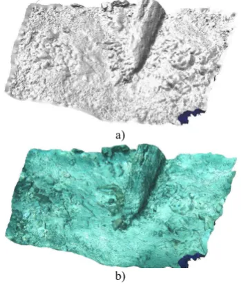
After the alignment and lens calibration, the software allows those coordinates that do not meet certain criteria to be removed: reprojection error, reconstruction uncertainty and image count. We chose to remove those points with a reprojection error of more than 0.5 pixels. In the software option, the reconstruction uncertainty has no units so we did not use it. The dense cloud can then be built followed by the mesh creation. The resulting mesh was exported to Polyworks for verification and clean-up and then re-imported into Photoscan in order to complete with the texture mapping step. Figure 16 shows a close-up view of the 3D model after excavation.
a)
b)
Figure 16. Close-up view of the 3D model created with Photoscan and images acquired after the excavation: a) shaded
view, b) texture mapped view.
During the imaging campaign the scale bars were available but for photo-aesthetic reasons only manual measurements of different dimensions were carried out. This was something that will be rectified in the future. Scale bars should be part of the photographic equipment. The manual measurements were used to scale the 3D model using CloudCompareV2 with an estimated error of about 2%. The resulting model is used here only for documentation and other qualitative purposes.
4. DISCUSSION
The application of 3D technology to underwater wooden artefacts has proved to be very useful. The advantages of the digital surveys using 3D imaging are well known in the context of various disciplines such as mechanical engineering and also archaeology. A digital 3D model not only facilitates the detailed study of the artefacts - apart from being non-contact - but also offers innovative analysis tools ranging from the possibility to zoom in on the model to examine and measure tiny surface details or to detect traces left by tool marks, understand woodworking, to the possibility of creating sectional views on the object without destroying it. The technology also ensures the reproducibility of the same physical archaeological artefact through the use of rapid prototyping technologies aimed at museum displays. Together, rapid prototyping and 3D digital models offer a unique opportunity to study the artefact remotely and enjoy it virtually.
With regard to the specimens from the boat of S. Sabina, the operation has allowed us to confirm the progressive decrease in the volume of wood extracted from the water, something which is already known, but it has allowed us to determine the time frame within which one can operate out of the water without the artefact suffering significant morphological changes. This is useful for example in scheduling 3D survey and a restoration. Thanks to this work, we have started to define a protocol to follow for all waterlogged wooden artefacts that need to be documented and restored. This protocol, once completed, will be applied to larger projects. In particular, the restoration will be carried out after a complete 3D survey at a very high resolution has been carried out. Here some observations are reported (non-exhaustive list):
The resolution is critical because one needs to measure in detail the surface of the artefact even on uniform reflectance areas.
In the scanning process, a verification tool/object of known size will always be added in the field of view near the artefact, e.g., mechanical object, scale bars, etc. Scanning must be completed within 2-4 hours from the
moment the object is extracted from the water, nevertheless on the same day in our typical environmental conditions of temperature and humidity.
First cracks tend to develop within the first few hours and overall dimensional changes are sudden after a few hours. The consolidated specimens will be resubmitted to a 3D scan to monitor changes in form and size as a result of consolidating treatment performed.
The specimen will be measured in 3D with the same tool and in the same manner as before restoration.
Any restored pieces should be the subject of a periodic digital 3D survey to confirm the success of the restoration.
During the experiments with our 3D imaging equipment, we
were confronted with the fact that rapid scanning and modelling were hindered by the absence of flow through and between hardware and software. The equipment was indeed designed for general purpose tasks. In the present situation, an active 3D scanning system where the scan head is fully integrated with the modelling software would be desirable. Real-time acquisition, data cleaning, mesh generation and visualisation, as 3D data is gathered, would have reduced our task significantly. From our evaluation, the latest commercial 3D imaging systems and solutions can reduce the scanning and model generation time by about a factor of five with respect to our current technology. Future projects will consider acquiring such equipment.
Furthermore, the use of a more flexible 3D passive technique, i.e., image-based dense stereo and multi-baseline methods for both laboratory use and for underwater documentation were experimented with, as non-expert users. No attempts were made to create a truly metric survey of our underwater site. The lack of scale bars and of a control network will be considered in the future along with a more in-depth study of the theory of underwater 3D reconstructions which are based on real models that include light refraction and propagation. Here the model of the shipwreck was sufficient to document our work qualitatively.
The use of photogrammetry in an underwater excavation proved to be highly useful:
It drastically decreases the time spent in water and needed for documentation of the wreck, detailed measurements, drawings, sections, etc., can be made directly on the 3D model.
It may be useful to monitor the conservation status of a submerged wreck even after many years.
As noted by many authors (Guidelines, 2010; Gregory, 2004; Palma, 2005), 3D imaging does not provide a complete picture. The examination of artefacts should be done by a wood specialist. Therefore, 3D imaging should not be seen as a replacement for the conservation and curation of wooden artefacts.
5. CONCLUSIONS
The UNESCO Convention 2001 (Law 157/2009) states that for the protection of underwater cultural heritage, the in-situ conservation should be considered as the first option for protection. As for the organic artefacts, however, in-situ conservation is not compatible with the protection and enjoyment of the property. For this reason it is very important, before embarking on a sometimes unpredictable road of expensive restorations, to meticulously measure the size and the characteristics of artefacts from the sea.
The experience of conservation and restoration on the artefacts from the excavations performed at the Chair of Underwater Archaeology and the SIBA 3D Lab of the University of Salento has placed us in the position of having to find solutions in parallel to the physical restoration of waterlogged artefacts.
This has opened up the possibility of extending virtual restoration to new forms of dimensional analysis and to ensure remote fruition of the artefacts. Digital modelling using 3D imaging technology (e.g. 3D laser scanners and image-based multi-view 3D reconstruction technology) will be integrated with current restoration and fruition protocols.
Finally, these active and passive 3D-imaging technologies ensure the reproducibility of archaeological artefacts using rapid prototyping technology and provide us with the opportunity to study remotely. Thus these technologies enable us to virtually bring about a new way of understanding our past and hence open a door into that past for future generations.
ACKNOWLEDGEMENTS
The authors would to acknowledge Agisoft® that graciously provided an evaluation copy of PhotoScan. Also thanks to Sarah Scott for her proofreading.
REFERENCES
3D laser scanning for heritage: advice and guidance to users on laser scanning in archaeology and architecture, 2nd Edition, English Heritage, 31/10/2011, c.41 pages, http://www.english-heritage.org.uk/publications/3d-laser-scanning-heritage2/ (accessed 02-2015).
Alfonso C., 2014. Torre S. Sabina. Il rilievo del relitto: tecniche tradizionali e fotogrammetria non convenzionale. In: Atti del III Convegno Nazionale di Archeologia Subacquea (Manfredona, 4-6 ottobre 2007), Bari.
Auriemma R, Silvestrelli F., 2013. Rotte e commerci marittimi tra Ellenismo e prima età imperiale: i giacimenti dell’Adriatico e dello Ionio”. In: Olcese G., Immensa Aequora. Atti del Convegno Roma 24-26 gennaio 2011, Roma, pp. 439-453.
Auriemma R., 2004. Salentum a salo. 1. Porti e approdi, rotte e scambi lungo la costa adriatica del Salento. 2. Forma Maris Antiqui, Collana del Dipartimento di Beni Culturali dell’Università di Lecce, Settore Storico-Archeologico, Galatina (LE, Italy).
Auriemma R., 2011. Nuovi dati dalla costa adriatica e ionica del Salento”. In: XVII International Archaeological Symposium «Navigare necesse est: from Prehistory to the Early Middle Ages» (Pula-Medulin-Rovinj, 23-26 November 2011), Histria Antiqua 21, pp. 536-556.
Auriemma R., 2014. Torre S. Sabina. L’approdo ritrovato: appunti di scavo. In: Atti del III Convegno Nazionale di Archeologia Subacquea (Manfredonia, 4-6 ottobre 2007), Bari.
Bandiera A., Alfonso, C., Auriemma, R., Di Bartolo, M. 2013. Monitoring and conservation of archaeological wooden elements from ship wrecks using 3D digital imaging. In: Proceedings of Digital Heritage International Congress (DigitalHeritage), 2013, pp. 113-118.
Beltrame C., 1996. Processi formativi del relitto in ambiente Mediterraneo. In: Volpe G., Archeologia subacquea. Come opera l'archeologo sott'acqua. Storie dalle acque, VIII Ciclo di Lezioni sulla Ricerca applicata in Archeologia. Certosa di Pontignano (Siena), 9-15 dicembre 1996, Firenze, pp. 141-166.
Boetto G., 1999. Il relitto di Monfalcone. L’archeologo subacqueo IV, 1 (13): 4.
Cocchiaro A., 1999. Carovigno (Brindisi), Torre Santa Sabina. Taras 19, 1, 121.
Colazzo M., 2011/2012. Characterization and study of the degradation of the wooden objects from underwater findings, academic thesis.
Cretté S.A., Näsänen L.M., González-Pereyra N.G., Rennison B. 2013. Conservation of waterlogged archaeological corks using supercritical CO2 and treatment monitoring using structured-light 3D scanning. The Journal of Supercritical Fluids, 79, pp. 299-313.
De Troia V., Machetti P., Remotti E., Spinetti A. 2007. Reperti archeologici in fibra organica e legno da ambienti umidi: problemi di documentazione e gestione ai fini scientific ed espositivi. In: Atti Convegno PRIN 2005, “La diagnostica e la conservazione di manufatti lignei: il legno bagnato”, Pisa 5-7 Dicembre 2007.
Drap P., Merad D., Mahiddine A., Seinturier J., Peloso D., Boï J.M., 2013. Underwater Photogrammetry for Archaeology. What Will Be the Next Step?. International Journal of Heritage in the Digital Era 2 (3), pp. 375-394.
Gregory D., 2004. Degradation of wooden shipwrecks: threats”. MoSS Newsletter 2/2004, pp.4–5.
Guidi G., Beraldin J.-A., Atzeni C., 2007. Wood artworks dimensional monitoring through high-resolution 3D cameras. In: Proc. SPIE 6491, Videometrics IX, 64910T (January 29, 2007.
Karsten A., Graeme E., 2010. HMS Stirling Castle, Kent: the Stirling Castle Wood Recording Project: a pilot study to compare traditional and innovative recording techniques for waterlogged wood: archaeological conservation report. English Heritage Research Reports 65, pp. 1-40.
Karsten A., Graham K., Jones J., Mould Q., Walton Rogers P., 2012. Waterlogged Organic Artefacts: Guidelines on their Recovery, Analysis and Conservation, English Heritage, 01/03/2012, c. 33 pages, http://www.english-heritage.org.uk/publications/waterlogged-organic-artefacts/ (accessed 02-2015).
Lanave, T., 2006. Sperimentazione del rilievo con laser 3d scanner su un reperto archeologico. L’archeologo subacqueo XI.1-2. Gen.-Ago. 2006, pp. 17-18.
Mirallès F., Beaudry J., Blain M., Romano M., De Santis R. H, Hurteau R, Robert A., Sarraillon S., Soucy N., 2010. Laser scanning system for inspecting large underwater hydroelectric structures. J. Electron. Imaging. 19(2).
Palma P., 2004. Final report for the monitoring theme of the MoSS Project. In: Cederlund, C O (ed) MoSS Final Report Monitoring, Safeguarding and Visualizing North-European Shipwreck Sites: Common European Cultural Heritage – Challenges for Cultural Resource Management Helsinki. The National Board of Antiquities, pp. 8–37, http://moss.nba.fi/download/final_report.pdf (accessed 02-2015).
Palma P., 2005. Monitoring of Shipwreck Sites. International Journal of Nautical Archaeology, Blackwell Publishing, Ltd.,Vol.34, Issue 2, pp. 323–331.
Petriaggi R., 2010. Alcune considerazioni sul trattamento dei legni archeologici imbibiti e sulle procedure di recupero e The International Archives of the Photogrammetry, Remote Sensing and Spatial Information Sciences, Volume XL-5/W5, 2015
restauro dei relitti antichi. In: Atti del I convegno nazionale Cesenatico, Museo della Marineria (4-5 aprile 2008).
Petriaggi R., 2010b. Consolidated procedures and new solutions for the in situ conservation, recovery and restoration of archaeological wood and ancient wrecks from underwater or water-saturated environments. Archeaologia Maritima Mediterranea 7, pp. 57-73.
Remondino, F., Del Pizzo, S., Kersten, T.P., Troisi, S., 2012. Low-cost and open-source solutions for automated image orientation – A critical overview. In: Proc. EuroMed 2012 Conference, M. Ioannides et al. (Eds.), LNCS 7616, Springer, Heidelberg, pp. 40-54.
Schindelholz E., 2005. An Evaluation of Supercritical Drying
and PEG/freeze Drying of Waterlogged Archaeological Wood. National Park Service, Harpers Ferry Center.
Shortis M.R., Harvey E.S., Abdo D.A., 2009. A review of underwater stereo-image measurement for marine biology and ecology applications. In: Oceanography and Marine Biology: An Annual Review, Vol. 47, Gibson, R. N., Atkinson, R. J. A. and Gordon, J. D. M. (Editors). CRC Press, Boca Raton FL, USA.
Waterlogged Wood: Guidelines on the recording, sampling, conservation and curation of waterlogged wood, 3rd Edition, English Heritage, 01/04/2010, c.37 pages. http://www.english-heritage.org.uk/publications/waterlogged-wood/ (accessed 02-2015)