3D Face Reconstruction With Local Feature Refinement
Rudy Adipranata
1, Kartika Gunadi
2and Wendy Gunawan
31,2
Informatics Department, Petra Christian University, Surabaya, Indonesia
1
[email protected],
2[email protected],
3
[email protected]
Abstract
In this paper, we propose 3D face reconstruction from two or three images. The reconstruction process begins with a face localization and facial feature extraction. Global transformation process is done for facial features which have been obtained. Local feature refinement is used to refine the result of global transformation. Last, texture mapping process is done to provide texture of 3D model. The method used for face reconstruction can generate accurate and fast result for various poses and facial expressions, and by using local feature refinement can improve the quality of reconstruction output more similar to the original face image.
Keywords: face reconstruction, local feature refinement, texture mapping
1. Introduction
3D reconstruction of the human face is a topic that is still actively developed today. The human face is one of the models that are difficult to reconstruct in three dimensions due to variations of the human face shape, skin color variation, the estimated depth of facial components. The need for 3D facial reconstruction has been growing in applications such as face recognition, three-dimensional games, virtual reality, animation, etc. In general, the method to reconstruct can be divided into several categories, namely pure modeling techniques from images, 3D scanning techniques, image-based hybrid techniques [6, 9]. In pure modeling techniques from images, three-dimensional models made only based on the image [9]. These techniques perform reconstruction using 2D images only without estimating the 3D structure of the real, but only by doing a comparison of the rendered image. On 3D scanning techniques, there are 2 kinds of ways, namely active and passive. 3D scanning techniques are actively carried out by means of a three-dimensional scanner, 3D scanning techniques while passively carried by finding correspondences between multiple forms. Passive 3D scanning technique known as Shape from X where X can be means of movement, texture, shadow or stereo [7, 10, 12, 13]. In the hybrid technique, images and estimation of the data are used to perform reconstruction process.
2. Generic Face Model
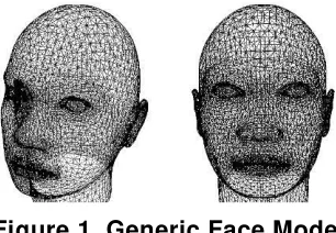
Generic face model is generally defined in terms of a triangular mesh consisting of vertices (coordinate points), edges (relations between two vertices) and face (set of edge). Generic face models can also be interpreted as a set of triangular mesh with vertices that can accommodate the important features of the face in performing face recognition. These features include the eyebrows, eyes, nose, mouth and face shape. Generic face model is an important part of a 3D face modeling. The level of accuracy in the modeling is also influenced by how detailed generic face model used [14]. In this research we used generic face model taken from a 3D human face in FaceGen Modeller application [17] which can be seen at Figure 1.
Figure 1. Generic Face Model
3. Face Localization and Facial Feature Extraction
Face localization is one of the stages of face detection, which aims to obtain a candidate region of human face through the process of skin color detection. In the process of skin color detection, the process of analysis will be carried out in two color models, normalization of RGB (red, green, blue) and HSV (hue, saturation, value). From the analysis by using a combination of the two color models, it can be determined which parts of an image that includes skin-color and what is not. According to Wang and Yuan [16], the boundaries of which can be accepted as the limit of human skin color is as follows in equation (1).
0 . 1 35
. 0 , 68 . 0 20
. 0 , 50 0
, 363 . 0 28
. 0 , 465 . 0 36
. 0
V S
H
g r
(1)
After the identification of the parts of a digital image that is included in the category of skin color, next process is combining parts to form a face candidate region and doing facial feature candidate extraction. Facial feature candidate extraction is a step done in order to obtain the parts of an object's face. In this case, the normal human face regions generally consist of two eyes, nose and mouth. However, in the process of candidate facial feature extraction, the nasal passages are not considered due to the consideration that the nose has a color factor which is almost the same as human skin color in general. Therefore, the facial feature extraction, the eyes and mouth factor is more dominant [14, 15].
hull process does not find any pixels that are included in human skin color criteria, the process will replace those pixels with a certain value of color which has been determined before. If the pixel has exactly the same value with the background pixel, the process will replace it with nothing. This rechecking convex hull process will stop if it has found a pixel which is included in human skin color criteria. Rechecking convex hull process has two types of direction, vertical direction and horizontal direction.
The face candidate area in YCbCr color models and the result of masking will be processed to determine the location of the eyes and mouth. For the mapping process of the eye, is divided into two stages: EyeMapL and EyeMapC. EyeMapL done based on the luminance component factors while EyeMapC performed by chrominance component factors. The equations to obtain EyeMapL and EyeMapC are as follows in equation (2) – (6) [14]:
( ) (~ ) ( / )
g is hemispheric structuring element which will be used as a structuring element in the gray-scale dilation and gray-scale erosion. R(x,y) is euchlidean distance from the center point of structuring element to any other point of the structuring element. W and
H are the width and height of the face candidate area. Fe is a constant defined as the maximum ratio between the size of the eyes and the size of a human face.
Mapping of both equations EyeMapL and EyeMapC will be operated by AND operator to get EyeMap region. To clarify the eye region, dilation operation can be performed. For the mapping of the mouth, can be obtained through the equation (7) – (8) [14]:
2
between the average value of 2
Cr and average value of Cr /Cb . n is the number of pixels
in face candidate area.
After obtaining the candidate eye and mouth area through the facial area candidate feature extraction, selection process will then be carried to the facial area candidate feature itself. This selection process can generally be divided into two main parts: the iterative thresholding and the selection of center of mass of the face candidate [14].
4. Global Transformation
In the 2D model, has been set 35 points as the starting facial features point which is forward-looking facial features and the face looks the left side and right side [9]. Then, using 9 features points that have been obtained from the facial feature extraction, global transformation process is done to find the value of the transformation of other 26 features point. After calculation, the new 35 feature points will be illustrated in the 2D model and the user can change it back if it is considered less appropriate.
This global transformation includes scaling, rotation and translation t o the original point. SupposePMo is the feature points of the model and PInis the feature points from facial feature extraction. To be able to find the value of the transformation from PMo to
In
P , it is necessary to eliminate the translation and scale val ues of PMo and PIn [9].
Eliminating the translational component of the feature points can done by translating the points so that the mean of all the points is at the starting point as shown in equation (9)-(10). equation (9)-(10) with the norm using equation (11)-(12).
) using equation (13).
Mo T
In P
P
A (13)
To get the value of a scale and rotation transformation, singular value decomposition (SVD) process of the matrix A is done that generates U, S and V matrix using equation Rotation, scale and translation matrix can be calculated using equation (15)-(16)
5. Local Feature Refinement
Transforming the global 3D model is not enough to highlight important features on the human face. This is because each feature has different transformations value. It is difficult to obtain a transformation matrix that can precisely place all of feature points correspond to the input image. Therefore we need the local transformation at each important facial feature such as eyes, nose and mouth in order to get more accurate 3D model result. Local transformation consists of local alignment and local feature refinement process [14]. Local alignment is the process to transform the model features such as eyes, nose, mouth, and chin to match the facial features. Local feature refinement is a process to improve the model so as to blend with the local features that have been transformed.
The process of local alignment is done by finding the value of the transformation of a generic face model that has been transformed globally into 3D points. Searching on the value transformation can be done using two methods. First method is the same as the global transformation process. The difference is only on the number of feature points used. Since global transformation is done throughout all of feature points, the local transformation is done only to feature points that are part of the local features. The second method is to calculate the transformation of the square by comparing the width and height of the model with three-dimensional coordinates from calculation. The second method is better than the first method that using singular value decomposition. This is because the SVD process only produces a single scale value. If there is a difference in scale between x coordinate with y coordinate, the SVD will look for the nearest value. Square transformation can be calculated using equation (18)-(21) [14].
Tr is translation of xcoordinate, Try is translation of y coordinate
x
h is height of local feature of point calculation result, hMo is height of local feature of 3D
model
from local feature of 3D model
In
y
C is centroid of y from local feature of point calculation result, CyMo CxMo is centroid
of x from local feature of 3D model
Centroid of polygon can be calculated using equation (22)-(24).
computer networks. Suppose Niis the number of vertex which is connected to vertex Vi, Ji is a collection of vertex connected to Vi, wiis the sum of euclidean distance of each vertex which is connected to Vi, and dij is the euclidean distance between vertex Viand vertex Vj.Suppose Vj is value of vertex Vjchanges and is decay factor, a value that will change
when the distance between two points changed. The calculation of the contribution to the displacement of vertex Vj from displacement of vertex Vican be seen in the equation (25)-(26) [14].
6. Texture Mapping
Texture mapping is the process of attaching an image or texture to a polygon. Texture mapping allows the depiction of the entire image is used as a texture in a polygon. Texture mapping also ensure the proper texture delineation when a polygon is transformed. Texture itself is a collection of data such as data color, lighting and transparency. Individual value at texture array is often referred as a texel [11].
Texture mapping process begins with a moving image input from user to an area that is used for mapping. Next process is to determine correlation of each vertex of 3D models in the mapping area. Due to the correlation between the vertex and mapping area already contained in the 3DS template we used, then the problem is how to move the right image input to the existing mapping area. To resolve this problem, we use the image warping approach with reverse mapping method.
Reverse mapping is one method in image warping which begin from the target image. Target image will be checked pixel by pixel to find pixel match to the source image. The advantage of the reverse mapping is each pixel in the target image definitely gets a pair in the source image [8].
Figure 2. Division of Facial Region by Using 35 Feature Points
7. Experimental Results
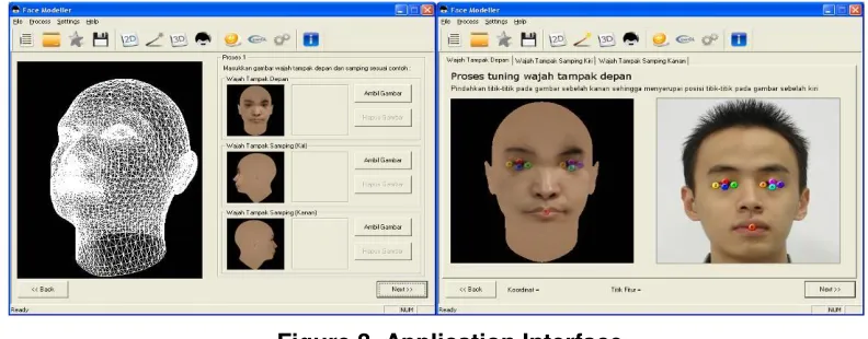
We developed the application using C++ and the interface can be seen in Figure 3 as follows.
Figure 3. Application Interface
Figure 4. Experimental Result
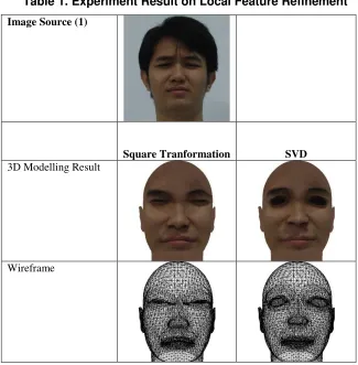
We also conducted experiment on local feature refinement. We compare the result of local feature refinement using both methods, square transformation and SVD. The experiment result on this can be seen in Table 1.
Table 1. Experiment Result on Local Feature Refinement
Image Source (1)
Square Tranformation SVD
3D Modelling Result
Processing time 10.875 seconds 7.953 seconds
Image Source (2)
Square Tranformation SVD
3D Modelling Result
Wireframe
Processing time 10.315 seconds 7.969 seconds
Image Source (3)
Square Tranformation SVD
3D Modelling Result
Wireframe
From the results of experiments conducted, it is seen that the results of 3D modeling by using square transformation better than using SVD because it is more similar to the original face images. However, the speed of the square transformation process is slower than the speed of SVD process.
8. Conclusion
In this paper, we have proposed 3D face reconstruction from two or three images using local feature refinement. Local feature refinement process gives better results, and along with the increasing of iterations number, the better the results will be obtained, but if the iteration number is too large, it will only increase processing time without significant difference result. From experiment result, the method used for face reconstruction can generate accurate and fast result and allow to synthesis various poses and facial expressions corresponding to the original face like lip mimic, glance of the eyes, etc. The local feature refinement using square transformation is able to produce a better result than using singular value decomposition but takes a little longer.
References
[1] M. Pamplona Segundo, “Improving 3D face reconstruction from a single image using half-frontal face poses”, Proceedings of 19th IEEE International Conference on Image Processing (2012) September 30- October 3. [2] I. Kemelmacher-Shlizerman and R. Basri, “3D Face Reconstruction from a Single Image using a Single
Reference Face Shape”, IEEE Transactions on Pattern Analysis and Machine Intelligence, vol. 33, no. 2, (2011).
[3] X. Fan, Q. Peng and M. Zhong, “3D Face Reconstruction from Single 2D Image Based on Robust Facial Feature Points Extraction and Generic Wire Frame Model”, Proceedings of International Conference on Communications and Mobile Computing, (2010) April 12-14.
[4] N. Patel and M. Zaveri, “3D Facial Model Construction and Expressions Synthesis using a Single Frontal
Face Image”, International Journal of Graphics, vol. 1, no.1, (2010).
[5] E. R. Adipranata, C. G. Ballangan and R. P. Ongkodjojo, “Fast Method for Multiple Human Face Segmentation in Color Image”, International Journal of Advanced Science and Technology, vol. 3, (2009) [6] W. N. Widanagamaachchi and A. T. Dharmaratne, “3D Face Reconstruction from 2D Images, a Survey”,
Proceedings of Digital Image Computing: Techniques and Applications (2008), December 1-3.
[7] S. H. Amin and D. Gillies, “Analysis of 3D face reconstruction”, In Proceedings of the 14th IEEE International Conference on Image Analysis and Processing, (2007) September 10-14.
[8] T. Funkhouser, “Image warping, compositing and warping”, Princeton University, Department of Computer Science, (2006).
[9] N. Rasiwasia, “The avatar: 3-d face reconstruction from two orthogonal pictures with application to facial makeover”, (2005).
[10]D. Samaras, S. Wang and L. Zhang, “Face reconstruction across different poses and arbitrary illumination conditions”, Proceedings of Fifth International Conference on Audio and Video based Biometric Person Authentication, (2005) July 20-22.
[11]T. Davis, J. Neider, D. Shreiner and M. Woo, “OpenGL programming guide (4th ed.). Addison-Wesley, Boston (2004).
[12]J. Lee, R. Machiraju, M. Baback and H. Pfister, “Silhouette-based 3d face shape recovery”, Graphics Interface, (2003).
[13]C. H. Esteban, and F. Schmitt, “Silhouette and Stereo Fusion for 3D Object Modeling”, Proceedings of Fourth International Conference on 3-D Digital Imaging and Modeling, (2003) October 06-10.
[14]R.-L. Hsu, M. Abdel-mottaleb and A. K. Jain, “Face Detection In Color Images”, IEEE Transactions on Pattern Analysis and Machine Intelligence, vol. 24, no. 5, (2002).
[15]K. Sandeep and A. N. Rajagopalan, “Human Face Detection in Cluttered Color Images Using Skin Color and
Edge Information”, Proceedings of Indian Conference of Computer Vision, Graphics and Image Processing, (2002) December 16-18.
[16]Y. Wang and B. Yuan, “A novel approach for human face detection from color images under complex background. Pattern Recognition, vol. 34, no. 10, (2001).
Authors
Rudy Adipranata is currently a senior lecturer in Informatics Department, Petra Christian University, Surabaya, Indonesia. He received his bachelor degree in Electrical Engineering from Petra Christian University, Surabaya, Indonesia, and master degree in Software Engineering from Graduate School of Software, Dongseo University, Busan, South Korea. His research interests are image processing and computer vision.
Rudy Adipranata is currently a senior lecturer in Informatics Department, Petra Christian University, Surabaya, Indonesia. He received his bachelor degree in Electrical Engineering from Petra Christian University, Surabaya, Indonesia, and master degree in Software Engineering from Graduate School of Software, Dongseo University, Busan, South Korea. His research interests are image processing and computer vision.