Fatigue Behavior of Resistance Spot-Welded Unequal Sheet
Thickness Austenitic Stainless Steel
Triyono1, Jamasri2, M. N. Ilman2 & R. Soekrisno2
1
Mechanical Engineering Department, Sebelas Maret University, Indonesia
2
Mechanical and Industrial Engineering Department, Gadjah Mada University, Indonesia
Correspondence: Triyono, Mechanical Engineering Department, Sebelas Maret University, Jl. Ir. Sutami 36A Surakarta, Indonesia. Tel: 62-27-163-2163. E-mail: [email protected]
Received: December 5, 2011 Accepted: April 7, 2012 Online Published: May 1, 2012 doi:10.5539/mas.v6n5p34 URL: http://dx.doi.org/10.5539/mas.v6n5p34
The research is financed by the Ministry of Research and Technology of Indonesia and Indonesian Railway Industry
Abstract
This paper presents a comparative study on the fatigue strength of resistance spot-welded unequal and equal sheet thickness austenitic stainless steel. Lap joints of 3.0-1.0 mm and 1.0-1.0 mm thick austenitic stainless steel were made using the same resistance spot welding schedule with current, weld time and electrode force of 4.7 kA, 20 cycles and 6 kN respectively. The sinusoidal wave form with a constant stress amplitude was selected in the fatigue tests whereas the stress ratio and frequency used were 0.1 and 8 Hz respectively. Fatigue strength and tensile-shear load bearing capacity of 3.0-1.0 mm joint were higher than that of 1.0-1.0 mm joint, although its nugget diameter was smaller. The joint stiffness was the controlling factor of the fatigue strength of resistance spot-welded unequal sheet thickness austenitic stainless steel.
Keywords: resistance spot welding, unequal sheet thickness, fatigue, austenitic stainless steel
1. Introduction
Austenitic stainless steels are used for a very broad range of applications especially in automotive, railway vehicle, ship body, and airplane structures when an excellent combination of strength and corrosion resistance in aqueous solutions at ambient temperature is required. Stiffened thin plate construction where the thinner plate is reinforced by thicker plate called a frame, is generally applied to the structures. Gean et al. (1999) have claimed that it is a cost-effective way of achieving a high-performance vehicle structure because it remains suited to low-volume manufacture. This structure is typically joined by the resistance spot welding (RSW) process. The advantages of using RSW are that it is a quicker joining technique, suitable for automation, no filler material is required, and that the low heat input implies less risk for altered dimensions during welding.
Many standards and recommendations are developed by individual companies, such as Ford Motor Company and General Motors. Professional organizations such as the American Welding Society (AWS), Society of Automotive Engineering (SAE), the American National Standards Institute (ANSI), and International Organization for Standardization (ISO) also contribute to a significant portion of the standards. Because of the drastic differences in design, understanding and perception of weld quality, automobile manufacturers and others tend to have very different requirements on weld quality. Zhang and Hongyan (2006) have concluded that in general, spot weld size is enveloped between 3√ and 6√ (t is the thickness of the sheets in millimeters). This recommendation is very useful in finding good weld schedules for equal sheet thickness welding. However, in automotive body application, the majority of welds are between two dissimilar thicknesses. In this case, schedules for welding unequal sheet thickness are generally developed by and practiced within individual manufacturers. Some researchers also have proposed the spot welding unequal sheet thickness researches to evaluate these recommendations. The joint of unequal thickness of the same metal may produce a strength problem due to the heat unbalance (Hasanbasoglu & Kacar, 2007) and have the unique failure mechanism (Pouranvari & Marashi, 2010).
have fo
ound that the s us fatigue crac esent work is ng austenitic sta
erimental Pro
aterials and We
ypes of austeni 0 mm joint and
nce spot weldi le 1 and 2 resp
1. The chemica
rial C
304 0,0
2. The mechan terial Yield
304
bile spot weldin with the elec mendations, th welding sched t possible with mined welding
were 4.7 kA, 2 ual conditions
etallography an
ansverse secti dure. The micr
chloric acid and ickers microha
tallographic sp
nsile-Shear Tes
ensile test of hydraulic SHI men are illustrat
spot welded joi cks are easily i to investigate ainless steel.
ocedure
Welding Process
tic stainless st d the other is d Strength (MP
305
ng machine W trode diamete he spot-weld nu dule required to hout causing e schedule used 20 cycles and in the Indones
nd Microhardn
ons of weld p rostructure of d 30 ml water. ardness measur pecimens with
sts
base metal a IMADZU uni
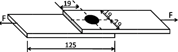
ted in Figure 1
Figure 1
int provides a initiated at thi and analyze f
ses
eel joints, one 1.0 mm and 1 he chemical co
n of test materi
Cr
18,107
s of test materi Pa) Tensile d for making th
6 kN respectiv sian Railway I
ness Measurem
passing throug f austenitic sta Microstructur rements across h a load of 500
and tensile-sh versal testing 1.
. Dimension o
localized conn s location und fatigue behavi
is the joint be 1.0 mm thick e Strength MPa)
670
uipment produc m and a curv
r was selected eld nugget size h in the 3.0-1.
he test sample vely. Fortunate Industry.
ments
gh the weld n ainless steel w
re investigation
nection which der fluctuating ior of the une
etween 3.0 mm joint called 1. d mechanical p
P Si
0,031 0,38
Elongation (%
55
ced by Mitsub ved surface r d between 3 an e was determin 0 mm joints a es including w
ely, this weldin
nugget were pr was revealed b ns were carried gget, HAZ, and
the spot-weld he geometry a
r test specimen
it is a source o loading. Ther qual sheet thi
m and 1.0 mm t .0-1.0 mm join properties of t
Cu
89 0,209
%) Electr
bishi Electric C adius of 100 nd 10.4 mm. Th
ned. This was and 1.0-1.0 mm
eld current, w ng schedule w
repared by sta by using 10 m d out using an d the base met
ded joint wer and dimension
ns (in mm)
of stress conce refore, the obje
ckness resista
thick hereinaft nt, were lap jo est materials a
Mo
he welding par done using the m joints samp eld time and e was in accordan
andard metallo ml nitric acids
optical micros tal were carrie
re performed ns of a typic
entration, ective of ance spot
These samples region at the c order to provid
2.4 Fatigue Te
The fatigue te SHIMADZU spot-welded te
These sample to provide sym ends of the sp ratio and frequ until fracture Applied force
3. Results and
The weld prof
Figure 3. W
It can be seen Because of th generated in t
s were similar center of the as de a tensile-sh
ests
ests were perfo testing machin est samples we
s were similar mmetry and to pecimen. A sin
uency used we occurred or to
range and num
d Discussion
file of 3.0-1.0 m
Weld profile of
n from Figure he unbalanced the thicker pla
to the sample ssembly repres hear loading co
formed at room ne with a softw ere made accor
Figure 2. Dim
r to the sample o prevent a mo nusoidal wave ere 0.1 and 8 H o a maximum 2
mber of cycles
mm joint is sh sents the nugge ondition, 38 mm
m temperature ware package s
rding to the Fr
mension of fat
es used in a wo oment being ap e input with a
Hz respectivel 2x10⁶ cycles. S s to failure wer
hown in Figure
hick joints (a)
nugget is asym g from unequal
oglu & Kacar,
ork which was et. The overlap m long shims w
in laboratory specifically des rench standard
tigue test speci
ork which was pplied at the w
constant load ly. Specimens Specimens tha re recorded and
e 3.
macrograph (b
mmetric where l thickness of
2007). Heat l
carried out by p is equal to th were attached
conditions us signed for runn d A03-405 as sh
imens (in mm)
s carried out by weld, 60mm lo amplitude wa were exposed at survived 2x1 d S-N curves f
b) nugget corn
e its centre lea the joined ma loss in thicker
y Gean et al. (1 he width of the at both ends o
sing a 40 kN s ning fatigue te hown in Figure
)
y Gean et al. ( ong shims wer as selected wh d to a constant
106 cycles are for the joints w
ner (c) nugget (
ans to the thic aterials, more t r plate is smal
1999). The dar e metal sheet. I of the specimen
servo-hydrauli ests. The doubl
e 2.
(1999). In orde re glued at bot hereas the stres load amplitud called run out were obtained.
(d) interface
thinner
r plate. This co Further evalua e indentation w ess causes the
et al., 2010). T ngated paralle niform manner hows interface d zone (HAZ) ent from the m
elded equal sh tion, nugget m ce of nugget an
ure 4. Weld pro
ition, accordin ints were spot lso the same, h ily attributed t als were found ess (Zhang & H ardness profiles
ure 5. Microhar
ondition causes ation of Figure was very sligh e edge of shee
The microstru el to irregular r from all the s e microstructu
.
microstructure heet thickness microstructure
nd base metal
ofile of 1.0-1.0
ng to the macro t welded using however that a to the asymmet d to be much h Hongyan, 2006 s of weld nugg
rdness distribu
s penetration i e 3(a) shows t ht. The asymm ets warp to the
cture of weld n r direction as ides of the sur ure where the
of spot welde austenitic stai has regular dir
as seen in Figu
0 mm thick joi
oscopic examin g the same we
at the joint int try nugget of 3 higher than a m 6). Therefore, get, HAZ (heat
ution of the spo
s almost 100% that separation metry of temp
e thinner shee nugget has a c shown in Fig rrounding solid base metal an
d unequal she inless steel sho
rection and w ure 4.
ints: (a) macro
nation (Figure elding schedule
erface were 8. 3.0-1.0 mm joi minimum nugg
the weld nugg t affected zone
ot welded equa
% on the thicke n of the sheets perature field d et and makes t columnar struc gure 3(c). It d, in both the e nd the nugget
eet thicknesses ows that the nu
ide heat affect
ograph (b) nugg
e 3 and Figure e, the nugget .3 mm and 8.9 int. The measu get diameter o get sizes of all e), and the base
al and unequal
er plate and ver s is about 20 distribution in the sheet sepa ture in which t shows that so electrode and s
are separated
, the microstru ugget is symm ted zone (HAZ
get corner (c) n
4) when the 3 diameter at ce 9 mm respectiv ured weld nugg of the 3-6 time welded materi e metal are sho
thickness aust
ry slight on the mm (Figure 3 n spot welded aration is high
the grains are olidification o sheet directions d by very narr
ucture investig metry, there is
Z) band appea
nugget (d) inte
.0-1.0 mm and enter of total th vely. This diffe get sizes for al es the root of t ials were accep own in Figure
j
The hardness The highest h However, hard joint because o carbon, manga the carbon con been used in hardness of th microstructure study, the ten stainless steel
As can be see 1.0-1.0 mm jo This result dif Ozyurek (200 welded joint. It seems that stiffness. As k rotation of the
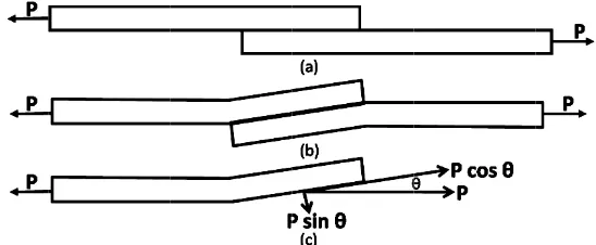
Figure 7. Defo
When there w
of nugget for b hardness value dness of the nu of the chemica anese that affe ntent exceeds this study had he thinner shee
e.
henomenon occ mpared to base s could be attr file of thin she etermine the lo nsile shear loa are compared
Figure
en from Figure oint even thou ffers from the 08). They foun
the enhancem known when t e joint. Figure
ormation mech
was certain amo
both 3.0-1.0 m of weld nugg ugget of 3.0-1 al composition ects the harden about 0.08% ( d less than th et of the 3.0-1.
curs in a thin s e metal unless
ributed to the et was more in oad range on th
ad bearing ca and results ar
e 6. Tensile she
e 6, the tensile ugh its nugget
results obtaine nd that increas
ment in tensile tensile load wa
7 shows the de
hanism of lap j
ount of rotation
mm and 1.0-1.0 gets was over 2
.0 mm joint di n of base metal nability. Spot w
(AWS, 1982; O hat of percent
0 mm joint co
sheet of the 3. s the nugget e asymmetric nu nfluenced by st
he fatigue test apacity of spo e given graphi
ear load bearin
e shear load be diameter at th ed from a wor ing of the nug
shearing load as applied in a eformation me
joint during lo load distributi
n, the tensile s
0 mm joint was 250 HV 0.5 w id not show m ls in which the welds in thin sh Ozyurek, 2008 carbon. In ad ompared to bas
0-1.0 mm join edge in which
ugget that occ train hardening ts, the strength ot welded equ
ically in Figure
ng capacity of
earing capacity he joint interfa rk which was c gget diameter
bearing capac a lap joint, the echanism of lap
ading, (a) low on in a lap join
stress called pe
s found to be h which was obs many difference ere is not so mu heet can have r 8). As seen in ddition, there w
se metal becau
nt where there h its hardness curred on the u
g due to electr h of weldment ual and unequ
e 6.
spot welded m
y of 3.0-1.0 m face is smaller
carried out by increased tens
city of 3.0-1.0 e eccentricity o
p joint during
load level, (b) nt
eeling stress (i
higher than tha erved on the e es compared to uch alloying el relatively high Table 1, base was no signifi use there was n
was no signif value was sim unequal sheet rode indentatio t was also dete ual sheet thick
materials
mm joint is high and it fail on Vural and Ak sile-shear stren
0 mm joint is a of the load pa loading.
) plastic hinges
.e. the normal
at of base meta edge of nugge o that of 1.0-1. lements such a h hardness whe metals that ha icant change i no change in it
ficant change i milar to nugge
thickness join on.
ermined. In thi kness austeniti
her than that o n the thin shee kkus (2004) an ngth of the spo
attributed to it ath resulted in
s, (c) schemati
the thro mation in sheet
nugget circum g stress of
3.0-Figure 8. The
load bearing c Nordberg, 2006
g capacity than
N curves, the r
Figure 9. Comp
ta points belon e life of the spe
0-1.0 mm join 7 kN.
erg (2006) has been analyzed. ated as follows
t1 > t2. The S
cycle relation and increasing
ss direction of thickness dire mference (Nor 1.0 mm joint w
(a) fracture mode
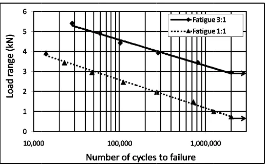
capacity of spo 6) this mecha n 1.0-1.0 mm j results of fatig
parison of fatig
nged to a mean ecimens increa nts. The endur
s proposed a l
the joint, exp ection. Increas rdberg, 2006). was smaller th
e of tensile she
ot welds under nism can exp oint.
ue test of the s
gue strength of
n value of three ases as expecte ance limit of 3
line load meth the load divid
e(
Figure 9 wil gure 10. At hi her at lower loa
ressed as P sin ing of the join . Due to the an that of
ear test sample
r coach-peel te plain why
3.0-spot welded jo
f 3.0-1.0 mm a
e tests. As show ed. The 3.0-1.0 3.0-1.0 mm joi
hod when fatig ded by the wi
3 2
14 t 3 )
ll has slightly igh loads fatig ads than that o
n θ) formed ar nt rotation incr
higher stiffne 1.0 mm joint a
s: (a) 3.0-1.0 m
est is much lo -1.0 mm joint
ints are presen
and 1.0-1.0 mm
wn in Figure 9 0 mm joints ex ints was 2.9 kN
gue data of dis idth of the joi
1 2
t
t
y different pat gue strength o of the 1.0-1.0 m
round the nug eased peeling ss, joint rotati as shown in Fi
(b)
mm joint (b) 1
ower than that t has a higher
nted in Figure 9
m joint based o
9, while the loa xhibited much h
N whereas tha
scontinuous jo
gget and cause stress that led ion and conse gure 8.
.0-1.0 mm join
of under tens r tensile shear
9.
on the load ran
ad range decre higher fatigue at of 1.0-1.0 m
oints like spot width of the jo
displayed in l mm joint was
Figure 10.
Similar to ten also attributed 3.0-1.0 mm jo occurred just Consequently, initiated on bo started in the b
After initiatio propagating th in Figure 12(a circumference behavior is si Khanna, 2007
Figu
Comparison o
nsile shearing l d to its stiffnes oint can be us on thin sheet , crack of 3.0-oth sheet side base metal adj
(a) Figure 1
on, the crack hrough the wid a). Different fr e due to high imilar to fractu 7).
ure 12. The frac
of fatigue stren
load bearing c ss. The explan sed to explain
t and it was s -1.0 mm joint as shown in F acent to the HA
1. Initial crack
propagation dth of the thin rom fracture of
peel stress an ure of coach p
(a) cture mode of
ngth of 3.0-1.0
capacity, the e nation of the e that in fatigu smaller than t initiated just igure 11. For b AZ area.
k location: (a)
of 3.0-1.0 mm sheet. Finally f 3.0-1.0 mm j nd led to the peel samples
fatigue test sam
mm and 1.0-1
enhancement in enhancement in ue strength. Du that of 1.0-1.0 on the thin sh both 3.0-1.0 m
(b) 3.0-1.0 mm jo
m joint occur y, this mechani oint, cracks of pull out fractu at high load t
mples: (a)
3.0-.0 mm joint ba
n fatigue stren n tensile shear ue to the high 0 mm joint w heet side wher mm and 1.0-1.0
oint (b) 1.0-1.0
rred through t ism led to the t f 1.0-1.0 mm j
ure mode as that reported i
(b) -1.0 mm joint
ased on the lin
ngth of 3.0-1.0 ring load bear her stiffness, r which rotated o
reas that of 1. 0 mm joint spe
mm joint
the thickness tearing fractur oint propagate shown in Figu in a previous
(b) 1.0-1.0 mm
ne load range
0 mm joint wa ring capacity o rotation of join on both sheet
0-1.0 mm join ecimens, crack
and continue re mode as see ed at the nugge
ure 12(b). Thi study (Long &
m joint
as of nt s. nt ks
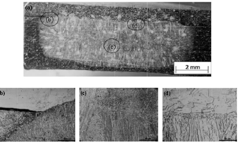
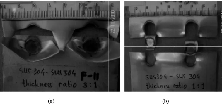
Given SEM views in Figure 13 and Figure 14 are the comparison of the last fracture surfaces of the 3.0-1.0 mm and 1.0-1.0 mm joint specimens which were subjected to same load of 3.4 kN. As seen in Figure 13(a), crack of 3.0-1.0 mm joint initiated on the inside of thin sheet. On the more half of thickness, it propagated slowly due to low peel stress and induced ductile fracture characterized by intergranular cracking. Ductile fracture changed to brittle fracture characterized by transgranular cracking on the remaining thickness due to increased peel stress. The embrittlement of stainless steel was attributed to strain-induced martensite forming during the fatigue tests (Vural et al., 2006). Different view was given by fracture surface of 1.0-1.0 mm joint specimen as shown in Figure 13(b). It displayed brittle fracture characterized by transgranular cracking on the entire thickness due to high peel stress.
(a) (b)
Figure 13. Initial crack of fatigue test samples: (a) 3.0-1.0 mm joint (b) 1.0-1.0 mm joint
(a) (b)
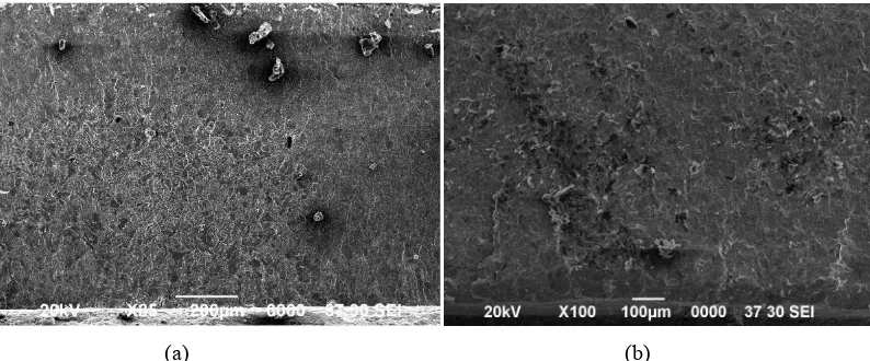
Figure 14. Crack propagation zone: (a) 3.0-1.0 mm joint (b) 1.0-1.0 mm joint
On the crack propagation zone, brittle fracture characterized by transgranular cracking was observed on both 3.0-1.0 mm and 1.0-1.0 mm joint specimens. They displayed wave of plastic deformation as shown in Figure 14. However, plastic deformation intensity of 1.0-1.0 mm joint was higher than that of 3.0-1.0 mm joint. It was indicated by the number of waves in the same observation area as seen in Figure 14.
4. Conclusions
steel.
5. Acknowledgments
The authors would like to express their sincere gratitude for the financial support of the Ministry of Research and Technology of Indonesia and Indonesian Railway Industry.
References
American Welding Society. (1982). Metals and their weldabilty, Welding handbook(7th ed.),4. United States of America.
Gean, A., Westgate, S. A., Kucza, J. C., & Ehrstrom, J. C. (1999). Static and Fatigue Behavior of Spot Welded 5182-0 Aluminium Alloy Sheet. Welding Journal, 78(3), 80s-86s.
Hasanbasoglu, A., & Kacar, R. (2007). Resistance Spot Weldability of Dissimilar Materials (AISI 316L-DIN EN 10130-99 Steels). Material and Design, 28, 1794-1800. http://dx.doi.org/10.1016/j.matdes.2006.05.013 Long, X., & Khanna, S. K. (2007). Fatigue properties and failure characterization of spot welded high strength
steel sheet. International Journal of Fatigue, 29, 879-886. http://dx.doi.org/10.1016/j.ijfatigue.2006.08.003 Nordberg, H. (2006). Fatigue Properties of Stainless Steel Lap Joints. SAE Transactions: Journal of Materials &
Manufacturing, 114, 675s-690s.
Ozyurek, D. (2008). An effect of weld current and weld atmosphere on the resistance spot weldability of 304L austenitic stainless steel. Materials and Design, 29, 597-603. http://dx.doi.org/10.1016/j.matdes.2007.03.008
Pouranvari, M., & Marashi, P. (2010). Resistance Spot Welding of Unequal Thickness Low Carbon Steel Sheet.
Advanced Materials Research, 83, 1205-1211.
http://dx.doi.org/10.4028/www.scientific.net/AMR.83-86.1205
Vural, M., & Akkus, A. (2004). On the resistance spot weldability of galvanized interstitial free steel sheets with austenitic stainless steel sheets. J. Mater. Proc. Technol., 153-154, 1-6. http://dx.doi.org/10.1016/j.jmatprotec.2004.04.063
Vural, M., Akkuş A., & Eryürek, B. (2006). Effect of Welding Nugget Diameter on The Fatigue Strength of The Resistance Spot Welded Joints of Different Steel Sheets. J. Mater. Proc. Technol., 176(1-3), 127-132. http://dx.doi.org/10.1016/j.jmatprotec.2006.02.026
Wang, Y., Zhang, P., Wu Y., & Hou, Z. (2010). Analysis of the Welding Deformation of Resistance Spot Welding for Sheet Metal with Unequal Thickness. Journal of Solid Mechanics and Material Engineering, 4,
1214-1222. http://dx.doi.org/10.1299/jmmp.4.1214