OPTICAL TRIANGULATION ON INSTATIONARY WATER SURFACES
,C. Mulsow a,*, H.-G. Maas a, B. Hentschel b
a Institute of Photogrammetry and Remote Sensing, Technische Universität Dresden 01062 Dresden, Germany, (christian.mulsow, hans-gerd.maas)@tu-dresden.de
b BAW, Kussmaulstrasse 17, D-76187 Karlsruhe, Germany[email protected]
Commission V/1
KEY WORDS: OpticalTriangulation, Water Surfaces, Laser Light Sheet
ABSTRACT:
The measurement of water surfaces is a key task in the field of experimental hydromechanics. Established techniques are usually gauge-based and often come with a large instrumental effort and a limited spatial resolution. The paper shows a photogrammetric alternative based on the well-known laser light sheet projection technique. While the original approach is limited to surfaces with diffuse reflection properties, the developed technique is capable of measuring dynamically on reflecting instationary surfaces. Contrary to the traditional way, the laser line is not observed on the object. Instead, using the properties of water, the laser light is reflected on to a set of staggered vertical planes. The resulting laser line is observed by a camera and measured by subpixel operators. A calibration based on known still water levels provides the parameters for the translation of image space measurements into water level and gradient determination in dynamic experiments. As a side-effect of the principle of measuring the reflected laser line rather than the projected one, the accuracy can be improved by almost a factor two. In experiments a standard deviation of 0.03 mm for water level changes could be achieved. The measuring rate corresponds to the frame rate of the camera. A complete measuring system is currently under development for the Federal Waterways Engineering and Research Institute (BAW).
This article shows the basic principle, potential and limitations of the method. Furthermore, several system variants optimised for different requirements are presented. Besides the geometrical models of different levels of complexity, system calibration procedures are described too. The applicability of the techniques and their accuracy potential are shown in several practical tests.
1. MOTIVATION
Despite improved analytical simulation techniques, the application of scaled physical models remains an essential method to solve complex problems in connection with project planning in river engineering (ATV-DVWK, 2004). For the verification of theoretical modelling approaches practical experiments on modelled systems like water channels (see Figure 1) are still necessary (Godding et al., 2003). One of the most important parameter for the description of hydromechanical phenomena is the water level height. Water surface models are often determined by point-wise water gauge measurements, monitoring the vertical motion of a floater or by ultrasonic height measurements in cylinders, which are connected with the channel bed via conduits.
Figure 1. Test bed of a river model, pointwise gauge measurement (source BAW)
These methods are limited in their temporal and spatial resolution, and they may affect the behaviour of the water surface. To overcome these limitations, a non-contact
profile-wise photogrammetric water surface measurement technique has been developed in a cooperation of the Institute of Photogrammetry and Remote Sensing at TU Dresden and the Federal Waterways Engineering and Research Institute (BAW) in Karlsruhe. Due to the surface properties of water (reflection and transparency) it is impossible to apply common structured light based optical surface measurement techniques. In the literature several attempts to overcome the problems by adapting established methods can be found. Basically, four different methods based on the characteristics of water can be identified:
Water as a diffuse reflective surface (eg. rough sea in a coastal zone, (De Vries et.al., 2009), (Santel et.al., 2004)) Artificial targeting of water surface or body (eg. markers on
the water surface (Henning et.al., 2007) or fluorescent particles in the water body (Große et.al., 2016)) Use of specular reflection properties (e.g. processing of
mirrored images of known objects, (Rupnik et.al., 2015)) Use of transparency of water (eg. observation of a
homogeneous light field through water, (Jähne et al. 2005))
The method presented in the following chapters uses the specular reflection properties of water. Depend on the intended use and grade of complexity, variations of the measuring principle will be described. Chapter 2 will explain the basic principle. Further, a simple system is described which is capable to measure water level changes of still water surfaces. Chapter 3 shows the expansion of the basic principle in order to enable the system to measure moving water surfaces. A system capable of measuring multiple profiles sequentially will be presented in chapter 4.
____________________________
* Corresponding author
2. MEASURING PRINCIPLE
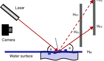
The method presented here uses the specular reflection properties of water surfaces in combination with optical triangulation (see figure 2). Basically, the measuring principle works as follows: a laser line is projected onto the water surface with an appropriate angle (~45°). The reflected laser line is then projected on to a vertical plane. Then the resulting line pattern is observed by a camera. Variations of the water surface will cause a change in the laser line pattern on the projection plane.
Figure 2: Basic measurement principle
In first instance the water surface will be dealt as a horizontal plane. By measurement of laser line change the water level change can be calculated by:
Laser
For calibration the conversion factor λ must be determined. This can be done simply by measurement of at least two known water level heights (see figure 3).
Figure 3: Optical triangulation using a vertical projection plane
The conversion factor can be calculated by following equation:
1
In case of an incident angle of laser light sheet of 45° and a vertical projection plane, the conversion factor λ=2. That means a sensitivity of the system for water level change of factor 2. The water level can be determined with high temporal resolution, which is only limited by frame rate of the camera used. The method was presented first by (Maas et.al., 2003). In experiments
achieved (0.7m wide profile, 1000x768 pixel video camera). But it was also shown, that the accuracy and reliability is prone to waves.
As figure 4 shows, the main problem of this projection-plane method is the ambiguity of effects causing a change of the laser line projection, which can either be caused by water level change or by slope variation. A compensation method for small regular waves based on image sequences was presented in (Maas et.al., 2003).
Figure 4: Effect of water movement on height measurement
3. TWO PLANE SYSTEM
A general solution of the wave problem can be achieved by the integration of a second vertical projection plane into the system (see figure 5). Now a complete reconstruction of reflected laser light sheet is possible. In addition to the water level height, also the surface normal direction can be obtained. Essential is here the knowledge about the relative orientation of system components, like the orientation of the projected laser light sheet as well as the projection planes. Furthermore a reference water level must be known.
Figure 5: Setup with two projection planes
Projection Plane
The main problem in this system design is the first vertical projection plane. This plane has to be semi-transparent. A practical solution was presented in (Mulsow et.al., 2006). Here the first vertical plane is constructed as a grid (see figure 6). This allows parts of the laser light sheet to pass through to the rear projection plane resulting a line pattern.
By connecting corresponding end-points of line segments on both projection planes, a vector can be created (figure 7), which can be intersected with the projected laser light sheet in order to obtain the water level height together with the water surface normal in the intersecting point (see figure 6).
Figure 7: Corresponding laser ends (left: still surface; right: dynamic surface)
4. MODELLING AND CALIBRATION
The calibration of a two plane system is more complex due to more components. Several methods were developed and implemented. The degree of complexity depends on the intended use, stability of the relative orientation of all relevant system parts and additional components. In the following chapter several approaches will be presented, starting from lower grade of complexity.
4.1 System with wave detection
Here the rear projection plane acts as a simple wave detector. A full reconstruction of the laser reflection is not necessary. The height measurement itself is performed in the same manner as with the single plane system. Image measurements of line elements on front grid are the input for water level calculation. Measurements on the rear projection planes provide information about the orientation of the water surface normal in the piercing point (see also figure 8). By calibration the system in the same way like the single-plane system, the relative conditions between laser measurements on both planes are known for the case of still water surface (horizontal plane). In fact, the measurements on the rear plane only provide the information if the water surface patch measured in that specific moment is horizontal orientated or not,
Figure 8: Detection of horizontal water surface element based on calibration on still water
This decision criterion can be described mathematical as follows:
1
Based on eq.3 now a separation between valid measurements on horizontal water surface patches and non-valid measurements on sloped surface patches is possible. If eq. 3 is fulfilled, the actual water level can be calculated in the same way as for the single plane system.
The approach only detects wave components for longitudinal direction only. For the lateral component (see figure 9), the principle presented above can be easily adapted.
Figure 9: shifts on rear plane induced by lateral waves
HW2 Line segments on rear plane
Figure 10: Validation of measurements on rear plane
By defining “corridors” on the rear plane based on calibration, valid measurements (without lateral slope) can be detected (see figure 10). Obviously, a “perfect” valid measurement on a temporal horizontal will never occur. By defining suitable thresholds the problem can be solved.
Another way is the interpolation of virtual measurements in the temporal domain. Each water surface patch is horizontal oriented for specific moments (assuming a random moving water surface).
Based on eq. 1, reference laser positions on the rear plane can be calculated from measurements on the front grid. By transferring the discrete laser measurements into functions, a continuous description of laser line movement on both planes can be computed in the temporal domain (e.g. quadratic functions). The point on the time axis, were the water surface patch was virtually horizontal can now be estimated by intersecting the function of reference with the function of line positions actually measured (see figure 11). In tests the presented approach showed good results and was therefore implemented in a system for use in laboratory environment at BAW. The accuracy was evaluated in first practical tests. From the results, a standard deviation of ~0.1 mm on a 20 cm wide profile can be estimated. Further tests have to be carried out in future. The main problem is here the provision of reference data for moving water surfaces.
Figure 11: Interpolation of valid measurements (example with sinusoidal wave in longitudinal direction): The red circles mark
virtual measurements of horizontal water surface patches
Figure 12: Measured water profile line over a time period of 4 seconds, acquired with 25 fps. The surface was interpolated between discrete profile points (blue dots).
Measured profile
HF2
HF1
valid measurement invalid measurements
HF
Correspondence between laser line segments
HR2
HR1 HR
4.2 System with strict reconstruction of laser reflection
A major limitation of the system with wave detection as described in 4.1 is in the fact that it delivers measurements only at (virtual) time instances with a horizontal surface. An essential step forward can be achieved by the full geometric reconstruction of the reflected laser light sheet and their intersection with the projected laser light sheet as mentioned in chapter 2. An essential requirement here is the determination of all relevant system parameters, like:
orientation of projected laser light sheet interior and exterior orientation of the camera orientation of projection planes
orientation of reference still water level
As seen in figure 13, all system components are mounted on a frame. The frame itself and on the projection planes are signalised by markers. This allows the determination of orientation of projection planes and provides a reference point field for camera calibration and orientation. Furthermore, the markers on the projection planes are used for transformation of image measurements of laser line segments in to object space (see also (Mulsow et.al., 2006)).
The construction of frame has to be rigid in order to ensure a stable geometry. The coordinates of the reference points can be measured with standard photogrammetric methods. In a next step, the camera can be calibrated and orientated via spatial resection. The projected laser light sheet can be determined for example by an integrated calibration procedure (see chapter 4.3.). The simplest way is to project the laser line onto a 3D-object and to measure the laser projection in an oriented set of photographs (spatial intersection). Of course, the mounting of the laser in the system has to be stable. Before measuring the actual water surface, a measurement on a still reference water level has to be carried out. The determined point coordinates on the water together with the surface normal define the plane parameters of the reference water surface.
Figure 13: System layout with step motor.
4.3 System with rotating laser light sheet
A further extension of the design concept is the ability to measure multiple profiles from one system position. For that task, a stepper motor rotating the projection unit was integrated into the system (see figure 13). This allows for variable settings of the incidence angle of the laser light sheet and a sequential measurement of multiple parallel profiles (see figure 14).
Figure 14: Variable setting of laser light sheet.
The angular rotation sensor of the stepper motor is able to provide the motor position with an accuracy of 0.001°. The detected laser line end points can be transformed into the 3D frame system with a precision of 0.2 mm on the vertical grid and 0.3 mm on the rear plane.
Figure 15: Data acquisition for calibration - direct and indirect projection at different rotation angles.
For calibration, a set of images of different laser sheet incidence angles is taken by the camera, both containing lightsheets directly projected onto the planes as well as indirectly (i.e. mirrored at the water surface), see figure 15. The laser segments are measured and transferred into object space. Together with the angle measurements from the angular rotation sensor, these coordinates are the input for the calibration model. The model itself is the mathematical description of the whole projection process together with the rotating laser light sheet. All necessary parameters can be determined in one integrated calibration procedure. A detailed description can be found in (Mulsow et al., 2006).
In experiments, an accuracy of 0.2 mm for water level changes measured on a 30 cm wide profile could be achieved. This means a decrease in precision comparing to the single plane system and the system with wave detection.
Profiles Step Motor
Laser
Camera
Water Surface Step motor
Profile 1 Profile 2 Profile 3
Laser
Camera
Water Surface Step motor
5. SYSTEM OPTIMISATION
The experimental setups as shown in section 3 and 4 showed the potential of the method but also the limitations. One major drawback for practical use in experimental hydromechanics is the physical dimension the system. The size of the frame is defined by the width of the profile to be measured as well as the accuracy requirements. By increasing the distance between the projection planes, the lever arm of the laser vector (between corresponding end points) gets longer, which means a better accuracy of the directional component of the vector. On the other hand, the increased travelling path of the reflected laser can cause a decrease in projection quality on the rear plane. Furthermore, the image scale becomes larger, which means a decrease in resolution of the laser projection in the camera image. Here an optimum has to be found. The use of a standard laser line module with an opening angle >0° means an increase of line width in horizontal direction with growing projection distance. In the experimental setups presented above, the fan angle of the line laser was 45°. The measurement of a water profile of 20 cm needs a distance of the laser from the water surface of ~25 cm. The projection of the laser on the rear plane, for example 50 cm further back, has a width of 60 cm.
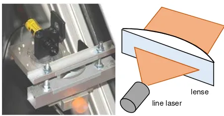
In order to ensure a complete projection, the size of the rear plane has to be quite large. To overcome this problem, a cylinder lens has been placed in front of the laser module. The width of the lens has to be at least as large as the intended profile width. A telecentric projection can be achieved by placing the pupil of the laser into the focal point of the lens. In the actual experimental setup, a cylinder lens of 20 cm width together with a line laser module with a fan angle of 45° is installed. This allows for measurements over a 20 cm profile. Therefore, the system dimension could be reduced significantly (see figure 17 and 18 left). A further improvement is the replacement of the grid with a slit plate as front projection plane (fig. 18). This generates a laser dot pattern rather than a line pattern on the rear plane. The detection and measurement of dots in image is usually more precise and faster compared to measuring line end points. On the front plane the corresponding point to the dot on the rear is represented by the intersection point of laser profile with the appropriate slit. Thus, the error prone determination of the laser line ends (especially the component along the line) can be avoided (see figure 18, right).
All necessary steps, like camera control, calibration and the measurement process itself can be controlled by the user in a comfortable graphical user interface.
Figure 16: Setup of a laser line module together with a cylinder lens (5cm), telecentric projection
Figure 17: Actual system with narrower frame and telecentric laser line. The basin under the system is for test purposes.
Figure 18: Left: Actual system with slit plate as front projection plane, Right: laser projection with slit plate (moving water)
Figure 19: Graphical user interface
line laser lense
500
mm
1000 mm
240 mm
6. CONCLUSION
The paper shows, that the general principle of optical triangulation can be adapted for measurement on water surfaces. Several modifications in the system design and in the data processing chain were implemented to adapt the system to measurements on instable water surfaces. A strict solution to measure height profiles on moving water surfaces has been realised and validated in several prototype systems.
The installation of an operational system at BAW will not mark the end of development. Experiences in practical use will led to further needs and therefore to further improvements.
REFERENCES
ATV-DVWK, 2003. Feststofftransportmodelle für Fließgewässer. In: ATV-DVWK-Arbeitsgruppe WW-2.4, March 2004
De Vries, S., Hill D., De Schipper, M.A., Stive M.J.F., 2009. Using Stereo Photogrammetry to Measure Coastal Waves. In:
Journal of Coastal Research, Special Issue No. 56. Proceedings of the 10th International Coastal Symposium ICS 2009, Vol. II (2009), pp. 1484-1488
Große, M., Schaffer, M., Weinfurtner, S., 2016. Kontinuierliche hochpräzise 3D-Oberflächenvermessung von Wasserwellen. In:
Proceedings of Oldenburger 3D-Tage 2016
Godding, R., Hentschel, B., Kauppert, K., 2003. Videometrie im Wasserbaulichem Versuchswesen. In: Wasserwirtschaft WAWI
4/2003, pp. 36-40
Henning, M., Saharhage, V., Hentschel, B., 2007. 3D-PTV – Ein System zur optischen Vermessung von Wasserspiegellagen und Fließgeschwindigkeiten in physikalischen Modellen. In:
Mitteilungsblatt der Bundesanstalt für Wasserbau Nr. 90
Jähne, B., Schmidt, M., Rocholz, R., 2005. Combined optical slope/height measurements of short wind waves: principle and calibration, In: Measurement Science and Technology, Volume 16, Number 10
Maas, H.-G., Hentschel, B., Schreiber, F., 2003. An optical triangulation method for height measurements on water surfaces. In: Videometrics VIII (Electronic Imaging 2003), Ed. S. El Hakim, SPIE Proceedings Series Vol. 5013
Mulsow, C., Schulze, M., Westfeld, P.,2006. An optical triangulation method for height measurements on non-stationary water surfaces. In: International Archives of the Photogrammetry, Remote Sensing and Spatial Information Sciences, pp. 213–217.
Rupnik, E., Jansa, J., Pfeifer, N., 2015. Sinusoidal Wave Estimation Using Photogrammetry and Short Video Sequences In: Sensors, 15,12.
Santel F., Linder, W, Heipke, C., 2004. Stereoscopic 3D-image sequence analysis of sea surfaces. In: Proceedings of the ISPRS Commission V Symposium, Istanbul, Turkey, Vol. 35, Part 5, pp. 708-712.