HIERARCHICAL MATCHING OF UNCERTAIN BUILDING MODELS WITH OBLIQUE
VIEW AIRBORNE IR IMAGE SEQUENCES
D. Iwaszczuk *, L. Hoegner, M. Schmitt, U. Stilla
Photogrammetry & Remote Sensing, Technische Universitaet Muenchen (TUM), Arcisstr. 21, 80333 Munich, Germany
{iwaszczuk, hoegner, schmitt, stilla}@bv.tum.de
Youth Forum
KEY WORDS: Urban, Matching, Infrared, Image, Sequences, Aerial, Mobile, Mapping
ABSTRACT:
Thermal building textures can be used for detection of damaged and weak spots in the building structure. These textures can be extracted from airborne infrared (IR) image sequences by projecting the 3D building model into the images. However, the direct geo-referencing is often not sufficiently accurate and the projected 3D model does not match the structures in the image. Thus we present a technique with the main goal to find the best fit between the existing 3D building model and the IR image sequence. For this purpose we developed a hierarchical approach consisting of two working stages. In the first stage we correct exterior orientation via line based matching. In the adjustment we consider both uncertainties: the ones of the model and the ones of the image. In the second stage we match each edge separately in its closest surrounding. Thanks to this approach a better fit between the 3D building model and the IR image was found. The originally unmodeled roof overlap was reconstructed.
1. INTRODUCTION 1.1 Motivation
Thermal inspections of buildings contribute to detection of damaged and weak spots in the building structure. 3D spatial reference of the captured images facilitates data interpretation of the data, especially for large area inspection using images taken from a flying platform. Thanks to multi aspect oblique view images roofs and walls are captured. Combining infrared (IR) images with 3D building models via texture mapping the spatial reference is achieved. For this purpose the existing 3D building models are projected into the infrared images and the building textures are extracted. For the projection the exterior and interior orientation parameters of the camera need to be known. These parameters can be determined directly from the navigation device and camera system calibration (camera calibration, bore-sight and lever-arm calibration). Unfortunately, the direct geo-referencing is often not accurate enough and the model does not match the structures in the image. To refine the registration a model-to-image matching should be carried out.
1.2 Related Work
In literature the matching problem is frequently discussed and many methods for solving the problem are presented. Some authors propose line matching based on slope and proximity (Frueh et al. 2004) or based on minimizing the disagreement between projected features and features detected in the image (Hsu et al., 2000). A drawback of these methods is relatively high computational effort. Alternative methods which use vanishing points can be applied for rough orientation (Ding & Zakhor, 2008; Foerstner 2010 b), which leads to faster results. However, in these methods so called “Manhattan scenes” are assumed, it means many horizontal and vertical lines have to be detected in the image. Other authors propose relational matching (Vosselman 1992; Eugster & Nebiker, 2009) which
considers relations between features and compares the relations in the image and in the 3D building models.
Most works on texture mapping and model-to-image matching consider the applied 3D building models as error-free. The uncertainty of the 3D building models was taken into account by few authors only. Sester & Foerstner (1989) used uncertain models stored in a parameterized form to localize the known roofs of the buildings. In contrast to this paper we propose a method to match a wireframe 3D building models with an IR image sequence. We use a line parameterization proposed by Roberts (1988), Schenk (2004), Meierhold et al. (2008) and define the uncertainty for both: image lines and model lines. Then we introduce a second step, which is similar to the recognition approach proposed by Lowe (1991) and adapted by Vosselman (1998) to align semi-automatically 3D building models to images. In contrast to these both researches and to Sester & Foerstner (1989), we don’t change the parameters of the model, but first recalculate the camera position to find the one, with the best model-to-image fit. Not till then we refine the position in the image for each model line allowing small changes of the geometry in the projected model, but not changing the 3D geometry of the building models.
2. METHOD OVERVIEW
The main goal of this work is to find the best fit between the existing 3D building model and IR image sequence. For this we propose a method for model-to-image matching consisting of two working stages.
We consider both uncertainties: the ones of the 3D building models and the ones of the image. The uncertainty of the building models is related to the inaccuracy of creation and generalization. The uncertainty of the image is result of errors in the geometry of the image caused by uncertain distortions and rolling shutter effect. Rolling shutter effect occurs in these IR cameras, for which each line is acquired in different time. International Archives of the Photogrammetry, Remote Sensing and Spatial Information Sciences, Volume XXXIX-B6, 2012
The camera position and orientation are assumed to be only approximately known. It is related to the platform vibrations. In case of UAVs or helicopters this effect is especially strong and can lead to a systematic error which is difficult to model in the calibration process.
In the first stage we correct exterior orientation. For this purpose we match the building model with the lines extracted in the image. In this stage very short model lines are not taken into consideration. Also highly detailed structures with lines lying close to each other are generalized or omitted. Therefore in this stage a lower level of abstraction is considered.
We assume roofs to be more reliable, because they are easier to detect than the ground edges. The radiometric properties of the ground (sidewalks and streets) in thermal IR are similar to the properties of the walls, thus edges between them appear blurred. Besides, in this paper we work with building models which are created using nadir view aerial imagery. In this case the roofs and building height are reconstructed, but the exact position of the walls (roof overlap) is often not modeled.
In contrast to Avbelj et al., 2010 we don’t use the intersection points but apply a line based matching using least squares method to recalculate the camera position, which improves the fit between the model and the structure in the image.
In the second stage we search for the best fit in the surrounding of the projected edge. We allow small changes in the geometry of the projected faces, and use knowledge about the creation method of the model. Regarding the unmodeled roof overlap, small inward movements of the wall edges should be allowed. We store our model as sets of points. Basically, in this stage we also apply line matching; however, we don’t extract linear structures in the image, but instead calculate the gradient image and use all grey value gradients surrounding the projected edges to find the best fit. Small changes in the geometry of the face are allowed in 2D image plane only and are used for best texture extraction. The 3D geometry of the model lines is kept unchanged in both stages.
3. LINE BASED MATCHING OF THE ENTIRE MODEL 3.1 Line Parameterization
3.1.1 In 3D: Typically a line in 3D is described by a direction vector v and a point P. For this description any point P
belonging to the line can be used, which leads to ambiguities. To solve these problem Roberts (1988) introduced a line representation which is unique and unambiguous. This line representation was discussed, varied and applied in photogrammetric context by Schenk (2004).
This line representation is based on two orientation parameters (α, θ) and two positional parameters (Xs, Ys). The azimuth α and zenith θ can be deduced from the spherical coordinates of vector v. Xs, Ys are coordinates of the intersection point with the plane X’Y’, where X’Y’Z’ is the rotated original coordinate system XYZ, so that the Z’-axis is parallel to the line. All required equations to calculate these parameters are given by Schenk (2004) and Meierhold et al. (2008). Each point of the line can be expressed as
As we can see, using (1) all lines, also the vertical and horizontal ones, are defined. This parameterization uses the number of parameters which is equal to the degree of freedom of a 3D line. We use this representation of lines to express the edges of the 3D building model.
3.1.2 In 2D: Similarly, we should search for a 2D line representation which uses the minimal number of parameters and is defined for all cases. For this purpose the representation with angle γ and distance p can be used:
0 sin
cos y p
x
(2)where p is the shortest distance from the line to the origin of the coordinate system; γ is the direction angle of the normal vector to the line.
3.2 Correspondences
In this stage of the research we apply a simple assignment based on the angle difference between the lines and the distance (Fig.1). We build a buffer around each projected line segment of the model and accept the image features which are entire within the buffer. Only these line segments can be accepted which differ from the projected building line with angle smaller then a threshold. This simple search for correspondences is applicable for our case, because we assume to know the exterior orientation of the camera from the GPS/INS path precise enough. This algorithm results in multiple correspondences for each edge. We apply Markov Random Fields to select the optimal correspondence for each edge.
Figure 1. The principle of the correspondence search
3.3 Least Squares Adjustment
The mapping of the 3D coordinates into the image is given by the collinearity equations. The collinearity equations can be combined with (1) and from the line representation
n mx y
l: (3)
the parameters m and n can be calculated. Detailed equations needed to express m and n in terms of camera pose parameters are given by Meierhold et al. (2008). The authors mention also the problem of vertical image lines and propose to change the line representation to:
' ' :x m y n
l . (4)
The problem in case of adjustment is that some lines can change from non-vertical to vertical lines within the iterations and the Jacobian matrix has to be re-designed. To avoid this problem we use (2) and express γ and p in terms of camera orientation parameters (5) and use them as observations.
1
For the adjustment we use the least square method with the model: is vector of estimated unknowns; ݔሶ is vector of approximated values for unknowns.
Additionally we extend the observations with the 3D line parameters and with camera interior orientation, so that we can apply the uncertainty of the 3D building model:
3.4 Stochastic model
3.4.1 Propagation of uncertainty: Propagation of uncertainty (error propagation) is in statistics a method for calculation of the variables’ uncertainties. The variables’ uncertainties are calculated as a consequence of the uncertainty of parameters, which are used for the calculation of these variables. Assuming that x is the observation vector and y is vector of functions yi(xj), we can write after linearization
t Ax
y (8)
in which A is a Jacobian matrix. The covariance matrix Cxx of the observation vector is also given. Then the covariance of the functions yi can be expressed as:
Uncertainty of the 3D building model: The uncertainty of the 3D building models is a consequence of the extraction method and generalization. In case of the 3D models extracted from aerial imagery the accuracy of the 3D coordinates of the corners can be assumed to be in range of few decimetres. However the roofs are extracted more accurately. We use σxy=0.5 [m] and
σz=0.7 [m] for roof points and σxy=1.0 [m] and σz=1.4 [m] for wall points.
Using the model introduced in Section 3.2 the error propagation is conducted. For this purpose we use the equations given presented in Section 3.3 and create the vector of functions y
(from eq. 8) and the covariance matrix Cyy (from eq. 9) can be calculated.
The derivatives of vertical 3D lines are undefined and cause errors in the Cyy matrix. We solve this problem searching the lines which are not vertical and have similar length and adopt their accuracy for a vertical line. Besides, the error propagation method using line representation proposed in this paper is very sensitive to the distance of the 3D model to the origin of the coordinate system. It means that using the full world coordinates in the national coordinates systems we will get huge variances. It is necessary to work in local coordinate systems.
3.4.2 Image features uncertainty: The image features are uncertain as well. Here the geometric uncertainty is also calculated as presented in Section 3.3.1 as result of the uncertainty of 2D coordinates.
4. LOCAL EDGE MATCHING
After the first working stage in which we estimated the exterior orientation of the camera, the projected 3D building model is placed on the adjusted position in the image. To refine the fit in the second stage we apply a local matching for each edge independently. For this purpose we first calculate the gradient image and project the model into the gradient image. Around each edge’s we build a buffer which includes the pixels of the edge surrounding. The size of the buffer has to be adjusted to the allowed movements, in our case it will be few pixels wide. To compromise the unmodeled roof overlap we apply Bayesian International Archives of the Photogrammetry, Remote Sensing and Spatial Information Sciences, Volume XXXIX-B6, 2012
updating by setting the wall edges to be likely to move in inwards.
We use the gradient values within the buffer to find the edge with the sub-pixel accuracy. To reduce the computation time we do not take all pixels of the buffer but build intervals and take the points lying on the perpendicular line between the intervals (see Fig. 2). We again apply least square method to fit the line. As observations we set the pixel coordinates within the buffer. The gradient values are used as weights. The small gradients below a threshold are set to 0, so that they do not influence the result.
Figure 2. Gradient image, the projected line (cyan) and buffer points (red). The coordinates of the buffer points and the gradient value of their nearest neighbors are taken for adjustment.
5. EXPERIMENTAL RESULTS
For our experiments we used a test dataset acquired in a densely built city area in centre of Munich, Germany. The thermal images were taken with IR camera AIM 640 QLW FLIR with a frame rate 25 images per second, which was mounted on a platform carried by helicopter. The flying height was approximately 400 m above ground level. The camera was forward looking with an oblique view of approximately 45°. The size of the chip is 640 x 512 pixels. The helicopter flew over the test area four times, recording four strips of IR image sequences. Each strip consists of almost 130 frames of size 640 x 512 pixels.
The 3D building model was created semi-automatically from aerial images using commercial software for 3D building reconstruction from aerial images.
For direct geo-referencing we use data acquired by an Applanix POS AV 510 GPS/INS system with a 200 Hz frequency for INS and 1 Hz for GPS. GPS coordinates are used to correct the INS drift within the Kalman filter procedure. The recorded coordinates are referred to the center of the navigation device. The misalignment of the camera and GPS/INS coordinate systems is determined within an extended bundle adjustment and the exterior orientation parameters are estimated and used for model projection (Kolecki et al., 2010).
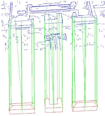
In Fig. 3 model projection after the calibration (in yellow and green) together with extracted image lines (in blue and red) is presented. In Fig. 3 model edges with found correspondences are highlighted in green and image lines which correspond to the model lines are highlighted in red. The width of the buffer is set to 20 pixels and the angle threshold to 10˚.
Figure 3. Extracted line segments (blue) and projected 3D building model (yellow) before matching. The model lines with correspondences are marked in green; in red – the extracted line segments with correspondences. The lines were extracted using Sobel filter.
Each model edge has got multiple correspondences. From these correspondences we select the most appropriate using Markov Random Fields (MRF) (Fig.4).
Figure 4. Correspondence selected using MRF.
In Fig. 5 the projected model before (green) and after projection (red) are displayed.
Figure 5. Projected model before adjustment (green) and after adjustment (red).
The results show improvement in position of the projected model. The estimated exterior orientation parameters where calculated with standard deviation in range of 3-5m and ca. 0.5˚. This positional accuracy is not very high, however we should consider that the IR image have lower resolution than VIS images and one pixel inaccuracy in the line extraction can cause an error of larger than 1m in 3D world coordinate system.
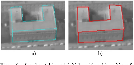
In the second stage we matched the model edges locally. Hence small roof overlaps could be corrected and therefore more precise texture mapping was achieved (see Fig. 6). The main advantage of this method is that the objects seen in the textures can be precise geo-referenced in the wall coordinate system. The wall coordinate system can be transformed into the world coordinate system. However for objects seen in thermal images (e.g. heat leakages) in case of building inspection is more important to identify them relatively to the building and not independently in 3D world coordinates.
a) b)
Figure 6. Local matching: a) initial position; b) position after local matching
6. DISCUSSION AND FUTURE WORK
Innovation of the presented technique consists in finding the best fit of the whole 3D building model in the first step and then allowing small changes in the face geometry in the second step. Most authors extracting textures do not consider the 3D model uncertainty, which is crucial for precise texture extraction. The 3D building models were extracted with uncertainty and generalized thus they cannot be assumed to be ground truth.
The IR image also cannot be considered as ground truth, because of the image distortions. In particular the rolling shutter effect makes the camera calibration difficult. However the roof overlap was not modeled at all. Hence, in the future a method for updating the 3D building models with the roof overlap can be developed and applied.
In the future the problem with undefined uncertainty for vertical lines should be solved. For this purpose another line representation should be chosen. Singularities free representation can be ensured in projective space (Meidow et al., 2009; Foerstner, 2010 b) and what be our focus for further research.
7. ACKNOWLEDGEMENTS
The authors would like to thank FGAN-FOM, Ettlingen, for providing images of the flight campaign and Mr. Oliver Maksymiuk for supporting the works with MRF.
REFERENCES References from Journals:
Lowe D G (1991) Fitting Parameterized Three-Dimensional Models to Images, IEEE Trans. Pattern Analysis and Machine Intelligence, vol. 13, no. 5, pp. 441-450
Meidow J, Beder C, Foerstner W (2009) Reasoning with uncertain points, straight lines, and straight line segments in 2D. In: ISPRS Journal of Photogrammetry and Remote Sensing, 64. Jg. 2009, Heft: 2, S. 125-139.
Schenk T (2004) From point-based to feature-based aerial triangulation. ISPRS Journal of Photogrammetry and Remote Sensing, 58 (2004), pp. 315-329
References from Books:
Vosselman G (1992) Relational matching. Lecture Notes in Computer Science. Berlin etc., Springer
References from Other Literature:
Avbelj J, Iwaszczuk D, Stilla U (2010) Matching of 3D wire-frame building models with image features from infrared video sequences taken by helicopters. International Archives of Photogrammetry, Remote Sensing and Spatial Geoinformation Sciences, 38(3B): 149-154
Ding M, Zakhor A (2008) Automatic registration of aerial imagery with untextured 3D LiDAR models, Proceedings of IEEE Computer Society Conference on Computer Vision and Pattern Recognition (CVPR)
Eugster H., Nebiker S. (2009) Real-time georegistration of video streams from mini or micro UAS using digital 3D city models. Proceedings of 6th International Symposium on Mobile Mapping Technology ‘09
Foerstner W (2010 a) Minimal Representations for Uncertainty and Estimation in Projective Spaces. In: Proceedings of the Asian Conference on Computer Vision. Queenstown, New Zealand 2010, S. 619-633, Part II.
Foerstner W (2010 b) Optimal vanishing point detection and rotation estimation of single image from a legoland scenes, International Archives of Photogrammetry, Remote Sensing and Spatial Geoinformation Sciences, Vol 38(3B): 157-162
Frueh C, Sammon R, Zakhor A (2004) Automated Texture Mapping of 3D City Models With Oblique Aerial Imagery, Proceedings of the 2nd International Symposium on 3D Data Processing, Visualization, and Transmission (3DPVT’04)
Hsu S, Samarasekera S, Kumar R, Sawhney H S (2000) Pose Estimation, Model Refinement, and Enhanced Visualization Using Video, Proceedings of CVPR 00, Hilton Head Is., SC, vol. I, pp.488-495
Kolecki J, Iwaszczuk D, Stilla U (2010) Calibration of an IR camera system for automatic texturing of 3D building models by direct geo-referenced images, Proceedings of Eurocow 2010
Meierhold N, Bienert A, Schmich A (2008) Linebased referencing between images and laser scanner data for image-based point cloud interpretation in a CAD environment. In The International Archives of the Photogrammetry, Remote Sensing and Spatial Information Sciences, 37 (B5), S. 437–444
Roberts K S (1988) A new representation for lines. IEEE Proceedings of Computer Vision and Pattern Recognition, 635– 640.
Schwermann R (1995) Geradengestützte Bildorientierung in der Nahbereichphotogrammetrie. Dissertation. Westfälische Technische Hochschule Aachen. ISSN 0515-0574
Sester M, Förstner W (1989) Object Location Based on Uncertain Models. In Burkhardt H, Höhne K H, Neumann B (Eds.) Muster Erkennung 1989, 11. DAGM-Symposium. Springer-Verlag London, UK ©1989. ISBN:3-540-51748-0, pp. 457-464
Vosselman G (1998) Interactive Alignment of Parameterised Object Models to Images. International Archives of Photogrammetry and Remote Sensing, 32 (Part 3/ 1):272-278