ON-ORBIT GEOMETRIC CALIBRATION APPROACH FOR HIGH-RESOLUTION
GEOSTATIONARY OPTICAL SATELLITE GaoFen-4
Mi Wanga, Yufeng Chenga,*, Xiaoxiang Longb, Bo Yangc
a State Key Laboratory of Information Engineering in Surveying, Mapping and Remote Sensing, Wuhan University, Wuhan 430079, China – [email protected] ; [email protected]
b China Center For Resources Satellite Data and Application, Beijing 100094, China – [email protected] c Collaborative Innovation Center of Geospatial Technology, Wuhan University, Wuhan 430079, China -
Commission I, WG I/4
KEY WORDS: GaoFen-4; high-resolution geostationary optical satellite; on-orbit geometric calibration; two-dimensional direction angle model; geometric accuracy
ABSTRACT:
The GaoFen-4 (GF-4) remote sensing satellite is China’s first civilian high-resolution geostationary optical satellite, which has been launched at the end of December 2015. To guarantee the geometric quality of imagery, this paper presents an on-orbit geometric calibration method for the area-array camera of GF-4. Firstly, we introduce the imaging features of area-array camera of GF-4 and construct a rigorous imaging model based on the analysis of the major error sources from three aspects: attitude measurement error, orbit measurement error and camera distortion. Secondly, we construct an on-orbit geometric calibration model by selecting and optimizing parameters of the rigorous geometric imaging model. On this basis, the calibration parameters are divided into two groups: external and internal calibration parameters. The external parameters are installation angles between the area-array camera and the star tracker, and we propose a two-dimensional direction angle model as internal parameters to describe the distortion of the area-array camera. Thirdly, we propose a stepwise parameters estimation method that external parameters are estimated firstly, then internal parameters are estimated based on the generalized camera frame determined by external parameters. Experiments based on the real data of GF-4 shows that after on-orbit geometric calibration, the geometric accuracy of the images without ground control points is significantly improved.
1. INTRODUCTION
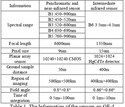
The Chinese GaoFen-4 (GF-4) remote sensing satellite is China’s first civilian high-resolution geostationary optical satellite, which has been launched at the end of December 2015. Geostationary satellite is located about 36000km over the earth's equator, and has many unique characteristics, such as the relatively fixed earth observation location, high temporal resolution, wide observation range, etc. GF-4 is equipped with three star trackers to determine satellite attitude. The platform of GF-4 uses the rigid connection between star trackers and the optical camera by rigid support. The optical camera has two planar array sensors, panchromatic and near-infrared sensor and intermediate infrared sensor, which are sharing the same optical lens and sensing different spectrums separated by colour separation filter. Panchromatic and near-infrared sensor can take images with different spectrums successively by rotary filter. The detailed information of the two sensors is listed in Table 1.
On-orbit geometric calibration is a key technology to guarantee the geometric quality of high-resolution optical satellite imagery (Grodecki, 2002; Grodecki, 2005; Junichi, 2009; Mattia, 2010). The camera of GF-4 is calibrated in ground-based laboratories to high precision before launching, including items of the camera geometric distortion and the installation angle between the optical camera and the star trackers (Yifu, 2015; Yongjun, 2014; Yonghua, 2014). However, vibration during launch and variation in thermal environment may alter the preset parameters. Therefore, it is necessary to redo these jobs during the mission (Delussy, 2012; Mulawa, 2004; Radhadevi, 2008; Radhadevi, 2011). For remote sensing camera of the satellites on low earth orbit (LEO), the traditional on-orbit geometric calibration methods basically use the ground control points (GCPs) generated by matching the satellite images with the reference digital orthophoto map (DOM) and
corresponding digital elevation model (DEM) of the high precision calibration field (Gruen, 2007; Takeo, 2009; Leea, 2008). External calibration and internal calibration are commonly included in the traditional calibration method (Baltsavias, 2006; Gachet, 2004; Jinshan, 2015; Wang, 2014; Guo, 2014). The external calibration means the determination of the installation of the camera, while the internal calibration means the determination of the camera’s internal distortion. Via on-orbit geometric calibration, the geometric accuracy of remote sensing images can be guaranteed. However, study on the geometric calibration of high-resolution geostationary optical satellite is very few at present.
Information near-infrared sensor Panchromatic and infrared sensor Intermediate
Spectral range
B1:450~900nm
B6:3.5um~4.1um B2:450~520nm
B3:520~600nm B4:630~690nm B5:760~900nm
Focal length 6600mm 1350mm
Pixel size 9um 15um
Planar array
sensor 10240×10240 CMOS HgCdTe detector 1024×1024 Ground sample
distance 50m 400m
Region of
imaging 500km×500km 400km×400km Field angle 0.8°×0.8° 0.66°×0.66°
Time of
integration 0.5ms~100ms 0.1ms~10ms Table 1. The Information of the sensors on GF-4 This paper develops an on-orbit geometric calibration approach for GF-4 to ensure the accuracy, in which a stepwise calibration is performed, external parameters estimated, and The International Archives of the Photogrammetry, Remote Sensing and Spatial Information Sciences, Volume XLI-B1, 2016
then internal parameters estimated in a generalized camera frame determined by external parameters. After calibration, combined with the star-camera-estimated attitude, every pixel of sensors can obtain a high-precision inertial line of sight (LOS) determined by the external and internal calibration parameters.
In this paper, we introduce the rigorous geometric imaging model of GF-4 and list all the internal and external error sources in Section 2. In Section 3, we build an on-orbit geometric calibration model and propose the corresponding estimation method of the calibration parameters. Section 4 details the on-orbit calibration results of GF-4. Last, Section 5 is the summary with conclusions. The proposed calibration model and estimation method have been proven to be stable and effective and could significantly improve the geometric accuracy of GF-4 satellite.
2. RIGOROUS GEOMETRIC IMAGING MODEL
Establishment of the rigorous geometric imaging model is the foundation of the establishment of on-orbit calibration model. To build a rigorous geometric imaging model, comprehensive analysis of external and internal errors of the camera is the necessary.
2.1 External Error Sources
External orientation parameters can be acquired with the aid of the devices for attitude and orbit determination. However, errors always exist in the external orientation parameters due to the limitation of the measurement accuracy of the devices and the effect of changes of the environment in space to the installation parameters. Therefore, it is necessary to calibrate the systemic error while weakening the influence of random error.
2.1.1 Orbit Measurement Error: The orbit data is usually observed by GPS receivers on LEO satellites. However, signal of GPS is not available for GF-4 because of its high orbit. Therefore, GF-4 use an afterwards orbit determination technology, whose accuracy will be superior to Km order of magnitude, to obtain the orbit data in the J2000 celestial coordinate system.
2.1.2 Attitude Measurement Error: Three APS star trackers and two gyros are equipped on GF-4 to determine satellite attitude, which defines the transformation matrix between the attitude determination reference coordinate system and the J2000 celestial coordinate system. Due to the high orbit of GF-4, the same attitude measurement error would cause much more deviation in image position determination without control than LEO satellites.
2.1.3 Camera Installation Error: The optical camera is rigid connected with star trackers by support, therefore, the accuracy of the installation will directly affect the accuracy of the camera’s attitude transformed from star trackers’. Limited in the assembly technology and affected by displacement during launching and orbiting, the true camera installation angle is probably deviated from the preset one on the ground.
2.2 Internal Error Sources
There are two groups of distortion errors in an optical camera. One is from the optical lens distortion, and the other from the focal plane translation, rotation, and the changing of the focal length. Because of the narrow field angle of the camera, the first-order radial distortion model with the first-order tangential distortion model is appropriate, more parameters or higher-order models do not have obvious advantages. Therefore, an internal geometric distortion model of planar array sensor can be constructed, as shown in Eq. (1).
sin sin cos cos sin sin sin sin cos cos
sin co focal plane frame whose principal point is the initial value.
Therefore, a rigorous geometric imaging model can be
the satellite’s coordinate in the J2000 coordinate system, which is obtained by the afterwards orbit determination technology. cam coordinate system, rotation matrix from the J2000 coordinate system to the star trackers’, and rotation matrix from the WGS84 to the J2000 coordinate system.
x y f, ,
T is the internal systematic error parameters, and
is proportional coefficient.3. ON-ORBIT GEOMETRIC CALIBRATION
APPROACH 3.1 Geometric calibration model
External angle element and line element are strongly correlated because of the high orbit and narrow field angle of GF-4. Then we can treat the orbit and attitude measurement error as a part of installation angle error to simplify error sources. As the orbit and attitude measurement error is random error, while the installation angle error is systematic error over a period of time. When we calibrate the real installation angle by one image, it’s inevitable that the random error will be absorbed into the calibrated installation angle. Therefore, strictly speaking, the installation angle should be calibrated by using multiple scenes of images to filter out the random error. Even though calibrating the installation angle by this method, random error will still reduce the positioning accuracy of each scene of image.
Although the camera physical measurement model in Eq. (1) considers the major internal errors in theory, the model is not practical as an on-orbit calibration model for the optical camera due to over-parameterization. Some parameters included in physical measurement model are strongly correlated because of unique imaging conditions (i.e., long focal length and narrow The International Archives of the Photogrammetry, Remote Sensing and Spatial Information Sciences, Volume XLI-B1, 2016
field angle). In addition, some parameters are less significant in imagery geometric accuracy. If using physical measurement model as the internal calibration model to calculate each parameter, the calculation equation would be seriously ill-conditioned, and thus the reliability and the accuracy of the calibration could not be ensured. Therefore, although the camera physical measurement model is rigorous in theory, it is not suitable for on-orbit internal calibration.
To solve the problem, a 2-dimensional detector directional angle model is adopted as the internal calibration model (as it shows in Figure 1). By calibrating the tangent of directional
Figure 1. Directional angle model of detector Polynomial model can be used to model the tangent of directional angles of detectors. As the internal distortion is low-order because of its narrow field of view, we use an individual three-order polynomial which has high orthogonality and low correlation as the internal calibration model.
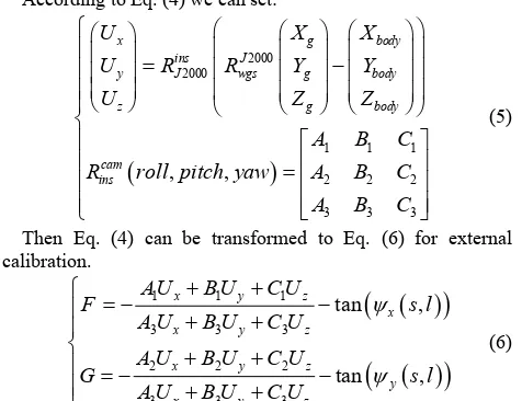
Then, an on-orbit geometric calibration model for GF-4 can be constructed as:
The external calibration parameter cam
, ,
E ins
X R roll pitch yaw is used to compensate the camera installation angle and determine the attitude of the camera coordinate system for internal calibration. The internal calibration parameter
0, , , , ,9 0 9
I
X a a b b is used to describe and compensate camera internal distortion.
A stepwise calibration is performed, external parameters estimated, and then internal parameters estimated in a generalized camera frame determined by external parameters. As some internal errors are included in the external calibration results, the reference coordinate system could not well represent the real camera coordinate system. However, this does not affect the calculation of internal calibration parameters because of the high correlation between external and internal calibration parameters on account of the narrow field angle. In addition, the proposed flexible internal calibration model could well compensate the residual errors that caused by external calibration, which would lower the precision requirement of external calibration. Once the internal parameters are determined on-orbit accurately, there would be no need to update them frequently, because they are relatively more stable than external parameters.
3.2 Estimation of the Camera Parameters
By matching the satellite image with the reference orthophoto and the corresponding DEM, we can automatically obtain GCPs. It is necessary to use a certain number and evenly distributed GCPs to ensure the quality of the parameters estimation. To guarantee the number and distribution of the matched GCPs, satellite image with no cloud and water cover should be selected, and mountainous area will be better choice to achieve more texture information for auto-matching because of the relative lower resolution. The coordinate of each control point
X Y Z
g, ,
g g i
is in the WGS84 geocentric euclidean coordinate system, and the corresponding coordinate of image point is
s l
,
i in the image plane coordinate system.N
is theTo determine external calibration parameters, we assume initial internal calibration parameters are “true”. We initialize the external and internal calibration parameters
X
E andX
Iwith on-ground calibration initial 0
E
X and 0
I
X . We define k the times of iteration.
Linearize Eq. (6) to get Eq. (7) as:
0 parameters obtained in kth iteration. E,
i k
is calculated in least-square method: 1
GCP in kth iteration in external calibration. Then k We repeat the estimation iteratively until k 1- k
E E
X X
where
is a small positive.Eq. (4) can be transformed to Eq. (10) for internal calibration.
true, and leave internal calibration parameters to be calibrated. Insert the modifiedX
E into the Eq. (10) and obtain Eq. (11).X
is the estimated internal calibration parameters. I iR is the vector of ith GCP in the camera frame calculated by current
X
E.Then we can obtain the modified internal parameters
X
I in least-square method:GCP in external calibration.
4. EXPERIMENT AND ANALYSIS
4.1 Experiment Data
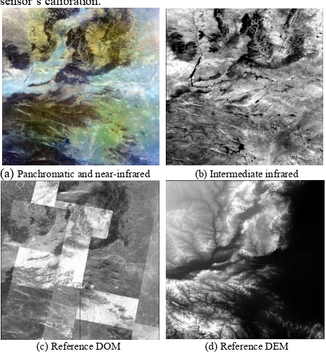
To verify the performance and effectiveness of the proposed calibration model and estimation method, an on-orbit geometric calibration experiment for GF-4 panchromatic and intermediate infrared sensor is performed. As the available calibration fields are not able to meet the requirement of the two sensors because of their large region of imaging (500km×500km and 400km×400km). We use the L1T panchromatic band data (200km×200km) of LandSat 8 provided by USGS as the reference data for the calibration of panchromatic sensor, whose resolution is 15 meters and nominal accuracy is about 12meters. We transformed the projection of the panchromatic images of LandSat 8 from TM projection to WGS84 projection and spliced them by ENVI5.1 to cover the selected panchromatic calibration scene of GF-4. The calibrated panchromatic images can be used as the reference data for the intermediate infrared sensor’s calibration.
(a) Panchromatic and near-infrared (b) Intermediate infrared
(c) Reference DOM (d) Reference DEM Figure 2. The selected satellite imagery and reference data Detailed information about the satellite imagery data and reference data are listed in Tables 1 and 2, respectively.
Table 2. Specific information about the satellite imagery data panchromatic image intermediate infrared
image
GSD (m) 50 400
Image Size
(pixels) 10240×10240 1024×1024
Acquisition The International Archives of the Photogrammetry, Remote Sensing and Spatial Information Sciences, Volume XLI-B1, 2016
Lower Left (E109.2,N31.8)
Lower Right (E114.6,N31.8)
Lower Left (E109.3,N32.1)
Lower Right (E113.9,N32.1) Table 3. Specific information about the reference data
DOM DEM
GSD (m) 15 30
Geometric Precision
(RMSE/m) Planimetric accuracy: 12 Height accuracy: 17
Area Covered Terrain type: Mountainous and Plains Range: 500km×500km
4.2 Results and Analysis
The panchromatic band (Band 1 in table. 1) image is chosen for the calibration of panchromatic and near-infrared sensor because of its higher radiant energy than the other bands, which is better for automatically matching method. By matching the GF-4’s panchromatic image with the reference DOM provided by LandSat 8, a number of corresponding point are automatically acquired which can be used as control points for the estimation of panchromatic sensor’s calibration parameters. The object coordinates of corresponding points can be directly obtained from the reference DOM and DEM. The triangulations are composed of 1,118,502 pervasive corresponding points that are obtained by auto-matching. Much more corresponding points in the mountain areas are obtained than the ones in the plain areas, to guarantee the uniform distribution of the control points in the whole image, 202,386 corresponding points are selected out as control points. The calibration parameters of panchromatic sensor are estimated by the control points and the values of the external calibration parameters before and after external calibration are listed in Table 4.
Table 4. External calibration parameters of panchromatic sensor
External parameters Before calibration After calibration Pitch (deg)
Roll (deg) Yaw (deg)
0.0 0.0 0.0
-0.028709 0.105105 0.384118
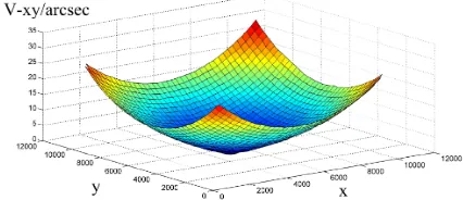
To analyse the characteristics of the sensor’s internal distortion objectively and quantitatively, the differences in directional angles of the detector of panchromatic sensor before and after internal calibration are shown in Figure 3. The new RPC file of the panchromatic image can be updated based on the obtained external and internal calibration parameters. The accuracy of the calibration can be evaluated by the 330 new evenly distributed corresponding points based on the updated RPC file, and the result is shown in Table 4.
Figure. 3 Internal distortion surface of panchromatic sensor
Table 4. Accuracy of the calibration of panchromatic sensor
X Y
External accuracy/pixel
Internal accuracy/pixel -0.097 0.467 0.090 0.427 The calibrated panchromatic image can be used as the reference DOM for the calibration of intermediate infrared sensor, to guarantee the accuracy of the registration of panchromatic and intermediate infrared images. Corresponding points are matched and selected as control points to estimate the calibration parameters. The values of the external calibration parameters before and after external calibration are listed in Table 5
Table 5. External calibration parameters of intermediate infrared sensor
External parameters Before calibration After calibration Pitch (deg)
Roll (deg) Yaw (deg)
0.0 0.0 0.0
0.026967 0.085769 0.194284 The differences in directional angles of the detector of intermediate infrared sensor before and after internal calibration are shown in Figure 4, and the accuracy of the calibration is shown in the Table 6.
Figure. 4 Internal distortion surface of intermediate infrared sensor
Table 6. Accuracy of the calibration of intermediate infrared sensor
X Y
External accuracy/pixel
Internal accuracy/pixel 0.122 0.286 0.056 0.410 As we can see, the geometric accuracy of both panchromatic and intermediate infrared sensors is highly improved by on-orbit calibration. To evaluate the overall performance of the data of GF-4 after calibration, 20 scene images are randomly selected to test the accuracy. The internal accuracy of both panchromatic and intermediate infrared sensors is better than 1 pixel, which is benefit from the internal calibration. The relative accuracy between images of the same area that simultaneous imaged by intermediate infrared and panchromatic sensor is better than 3 pixels (of intermediate infrared sensor), and the deviation may be caused by interpolation of attitude and orbit. The absolute accuracy without control of panchromatic sensor is only better than 15 km, which is much better than the one before calibration, however, it is not very desirable at present. That is may be caused by the thermal deformation of the support between the star trackers and the camera.
5. CONCLUSION
To guarantee the geometric quality of imagery, this paper presents an on-orbit geometric calibration method for the area-array camera of GF-4. Geometric accuracy of the images without ground control points is significantly improved. Internal accuracy of the both sensors is better than 1 pixel, which is much satisfactory. Although the absolute accuracy is much The International Archives of the Photogrammetry, Remote Sensing and Spatial Information Sciences, Volume XLI-B1, 2016
improved, it is still not desirable, which may be caused by the thermal deformation of the support between the star trackers and the camera and we will focus on this issue in the further research.
ACKNOWLEDGEMENTS
The authors would like to thank the accompaniers working with us in state key laboratory of information engineering in surveying, mapping and remote sensing and China centre for resources satellite data and application. We also thank to National Basic Research Program of China 973 Program (2014CB744201), National Natural Science Foundation of China (NSFC) (41371430, 91438111) and Program for Changjing Scholars and Innovative Research Team in University (IRT1278).
REFERENCES
Baltsavias, E, 2006. DSM generation and interior orientation determination of IKONOS images using a Testfield in Switzerland [J]. Photogramm. Fernerkund. Geoinf. 1: 41–54. Delussy, F, 2012. Pleiades HR in flight geometrical calibration: location and mapping of the focal plane [C]. ISPRS International Archives of the Photogrammetry, Remote Sensing and Spatial Information Sciences, 39: 519-523.
Gachet, R, 2004. SPOT5 In-flight Commission: Inner Orientation of HRG and HRS Instruments [J]. The International Archives of the Photogrammetry, Remote Sensing and Spatial Information Sciences, 35(Part B1): 535-539.
Grodecki, J, 2002. IKONOS Geometric Accuracy Validation [C]. Proceedings of ISPRS Commission I Mid-Term Symposium, Denver, USA, (on CD-ROM).
Grodecki, J, 2005. IKONOS Geometric Calibration [C]. Proceedings of the ASPRS 2005 Annual Conference, Baltimore, USA, (on CD-ROM).
Gruen, A, 2007. Calibration and Validation of Early ALOS/PRISM Imagery [J]. The Journal of Japan Society of Photogrammetry and Remote Sensing, 46(1): 24-38.
Guo, Z, 2014. In-orbit Geometric Calibration and Validation of ZY-3 Linear Array Sensors [J]. The Photogrammetric Record, 29(145): 68-88.
Junichi, T, 2009. PRISM on-orbit geometric calibration and DSM performance [J]. IEEE Trans. Geosci. Remote Sens, 47: 4060–4073.
Jinshan, C, 2015. In-orbit Geometric Calibration and Validation of ZY-3 Three-line Cameras Based on CCD-Detector Look Angles [J]. The Photogrammetric Record, 30(150): 211-226. Leea, D, H, 2008. Summary Of Calibration And Validation for Kompsat-2 [C]. The International Archives of the Photogrammetry, Remote Sensing and Spatial Information Sciences, 37(B1): 53-56.
Mulawa, D, 2004. On-Orbit Geometric Calibration of the OrbView-3 High Resolution Imaging Satellite [C]. The International Archives of the Photogrammetry, Remote Sensing and Spatial Information Sciences, 35(Part B1): 1-6
Mattia, C, 2010. GeoEye-1: Analysis of Radiometric and Geometric Capability. Lecture Notes of the Institute for
Compute Sciences, Social Informatics and Telecommunications Engineering [J], 43(7): 354-369.
Radhadevi, P, V, 2008. In-flight geometric calibration of different cameras of IRS-P6 using a physical sensor model [J]. Photogramm. Rec, 23: 69–89.
Radhadevi, P, V, 2011. In-flight geometric calibration and orientation of ALOS/PRISM imagery with a generic sensor model [J]. Photogramm. Eng. Remote Sens, 77: 531–538. Takeo, T, 2009. Calibration of PRISM and AVNIR-2 onboard ALOS―Daichi [J]. IEEE Trans. Geosci. Remote Sens, 47: 4042–4050.
Wang, M, 2014. On-Orbit geometric calibration model and its applications for high-resolution optical satellite imagery J]. Remote Sensing, 6(5): 4391-4408.
Yifu, C, 2015. Calibration and Validation of ZY-3 Optical Sensors. IEEE Transactions on Geoscience and Remote Sensing [J], 53(8): 4616-4626.
Yongjun, Z, 2014. On-orbit Geometric Calibration of ZY-3 Three-Line Array Imagery with Multistrip Data Sets [J]. IEEE Transactions on Geoscience and Remote Sensing, 52(1): 224-234.
Yonghua, J, 2014. Geometric Calibration and Accuracy Assessment of ZiYuan-3 Multispectral Images [J]. IEEE Transactions on Geoscience and Remote Sensing, 52(7): 4161-4172.