Wayland, MA 01778 Telephone: +1-508-655-5858
Facsimile: +1-508-655-2237 Editor:
George Percivall Telephone: +1-301-286-4073
The OpenGIS Abstract Specification
Topic 12: OpenGIS Service Architecture
Version 4.3
The information contained in this document is subject to change without notice.
The material in this document details an Open GIS Consortium (OGC) specification in accordance with the license and notice set forth on this page. This document does not represent a commitment to implement any portion of this specification in any companies products.
While the information in this publication is beleived to be accurate, the Open GIS Consortium makes no warranty of any kind with regard to this material including but not limited to the implied warranties of merchantability and fitness for a particular purpose. The Open GIS Consortium shall not be liable for errors contained herein or for incidental or consequential damages in connection with the furnishing, performance or use of this material. The information contained in this document is subject to change without notice.
The Open GIS Consortium is and shall at all times be the sole entity that may authorize developers, suppliers and sellers of computer software to use certification marks, trademarks, or other special designations to indicate compliance with these materials.
This document contains information which is protected by copyright. All Rights Reserved. Except as otherwise provided herein, no part of this work may be reproduced or used in any form or by any means (graphic, electronic, or mechanical including photocopying, recording, taping, or information storage and retrieval systems) without the permission of the copyright owner. All copies of this document must include the copyright and other information contained on this page.
Date Description
Carry 98-112r1 forward as 99-112; incorporate change proposal 99-009, approved 9 February 1999 into Section 5; follow guidance of change proposal 99-010 w/ friendly amendments to remove Section 1 boilerplate from individual topic volumes, approved 9 February 1999; incorporate change proposal 99-003 (Feature Linking), approved 9 February 1999; fix mislabeled heading (from Image Merging and Rectification Services to Image Map Generation Services); fix garbled heading.
May 2001 Version 4.1
Based on resolution adopted at OGC Technical Committee in April 2001, adopt ISO CD 19119.2 as OGC Topic 12.
September 2001 Version 4.2
Based on a resolution adopted at OGC Technical Committee in September 2001, adopt the final text of CD 19119 as OGC Topic 12. Additionally version 4.1 includes the contents of OGC document 045r1 as approved by the TC for inclusion during the June 2001 TC meeting. January 2002
Version 4.3
Incorporated ISO DIS 19119, replacing the final text of ISO CD 19119 in version 4.2. Retain the Future Work of Version 4.2. ISO/DIS 19119 Geographic information Services issued by ISO Central Secretariat for DIS Enquiry vote beginning on 2002-01-24.
Future Work
(Editors note: these future work items were made as OGC comments on the previous version of this document (Version 4.1) and have, in part, been resolved and implemented. The entire list as adopted at the June 2001 OGC meeting is retained here for completeness at this time.)
Improvement of this document is needed to meet all OGC Abstract Specification needs, including the following. 1. Adapt Annex A: Conformance, to meet OGC needs for compliance of OGC Implementation Specifications with the Abstract Specification. For example, either ISO/TS 19103 also needs to be adopted and distributed by the OGC, or the current compliance material needs to be adapted so that use of ISO/TS 19103 is not considered normative.
2. Add additional services to those now listed in Clause 7.3: Geospatial services, to include all high-level services known to the OGC, including all mentioned in the old Topic 12, OGC document 99-112. For example, the comments on ISO/CD 19119.2 submitted by OGC (written by Arliss Whiteside) suggested adding about nine services based on the old OGC Topic 12, and those suggestions are known to be incomplete.
3. Add service details as they are developed by various OGC Special Interest Groups and Working Groups (SIGs and WGs), including adding references to service details recorded in other parts of the OGC Abstract Specification. For example, Topic 15: Image Exploitation Services includes considerably more detail on some services.
ISO/TC 211 Secretariat: NSF
Voting begins on Voting terminates on
2002-01-24 2002-06-24
INTERNATIONAL ORGANIZATION FOR STANDARDIZATION • А АЯ А АЦ Я А А АЦ • ORGANISATION INTERNATIONALE DE NORMALISATION
Geographic information —
Services
Information géographique — Services
ICS 35.240.70
In accordance with the provisions of Council Resolution 15/1993 this document is circulated in the English language only.
Conformément aux dispositions de la Résolution du Conseil 15/1993, ce document est distribué en version anglaise seulement.
To expedite distribution, this document is circulated as received from the committee secretariat. ISO Central Secretariat work of editing and text composition will be undertaken at publication stage.
Pour accélérer la distribution, le présent document est distribué tel qu'il est parvenu du secrétariat du comité. Le travail de rédaction et de composition de texte sera effectué au Secrétariat central de l'ISO au stade de publication.
THIS DOCUMENT IS A DRAFT CIRCULATED FOR COMMENT AND APPROVAL. IT IS THEREFORE SUBJECT TO CHANGE AND MAY NOT BE REFERRED TO AS AN INTERNATIONAL STANDARD UNTIL PUBLISHED AS SUCH.
Copyright notice
This ISO document is a Draft International Standard and is copyright-protected by ISO. Except as permitted under the applicable laws of the user's country, neither this ISO draft nor any extract from it may be reproduced, stored in a retrieval system or transmitted in any form or by any means, electronic, photocopying, recording or otherwise, without prior written permission being secured.
Requests for permission to reproduce should be addressed to either ISO at the address below or ISO's member body in the country of the requester.
ISO copyright office
Case postale 56 • CH-1211 Geneva 20 Tel. + 41 22 749 01 11
Fax + 41 22 749 09 47 E-mail [email protected] Web www.iso.ch
Contents
Foreword ... vi
Introduction ... vi
1 Scope ... 1
2 Conformance ... 1
3 Normative references ... 1
4 Terms and definitions... 2
5 Abbreviated terms... 3
6 Overview of geographic services architecture ... 4
6.1 Purpose and justification ... 4
6.2 Interoperability reference model – based on ISO RM-ODP ... 4
6.3 Service Abstraction ... 6
6.4 Interoperability ... 6
6.5 Use of other geographic information standards in service specifications... 7
6.6 Architecture Patterns... 7
7 Computational viewpoint: a basis for service chaining... 8
7.1 Component and service interoperability and the computational viewpoint... 8
7.2 Services, interfaces and operations ... 8
7.3 Service chaining... 10
7.3.1 Introduction to Service Chaining ... 10
7.3.2 Anatomy of a service chain ... 10
7.3.3 Services organizer folder ... 12
7.3.4 Services to enable service chaining ... 12
7.3.5 Architecture patterns for service chaining ... 13
7.3.6 Variations on chaining patterns ... 18
7.4 Service metadata... 19
7.4.1 Introduction ... 19
7.4.2 Service metadata main class diagram ... 20
7.4.3 Data dictionary for geographic service metadata ... 21
7.5 Service instance of unknown type ... 21
7.6 Simple service architecture ... 22
8 Information viewpoint: a basis for semantic interoperability... 22
8.1 Information model interoperability and the information viewpoint ... 22
8.2 Extended open systems environment for geographic services ... 23
8.3 Geographic services taxonomy... 24
8.3.1 Geographic services taxonomy requirements... 24
8.3.2 Geographic human interaction services ... 25
8.3.3 Geographic model/information management services... 26
8.3.4 Geographic workflow/task management services ... 27
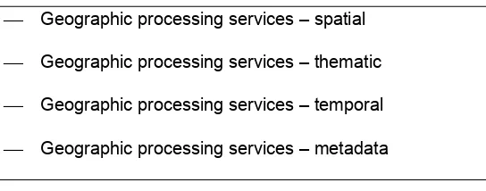
8.3.5 Geographic processing services ... 27
8.3.6 Geographic communication services ... 30
8.3.7 Geographic system management services ... 31
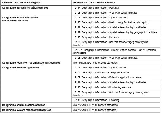
8.4 ISO 19100 series standards in geographic service taxonomy... 31
8.5 Geographic service chaining validity ... 31
8.6 Services organizer folder (SOF) ... 32
8.6.1 Introduction ... 32
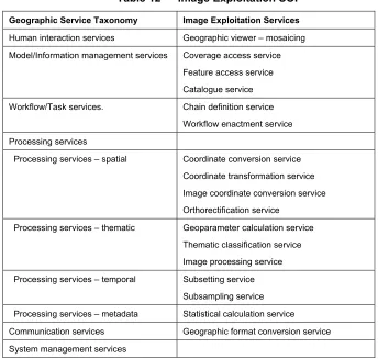
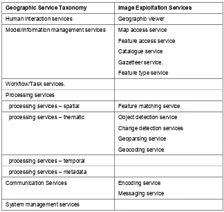
8.6.2 Image Exploitation SOF... 32
8.6.3 Geographic data fusion SOF ... 33
9.1 Distribution transparencies and the engineering viewpoint ... 34
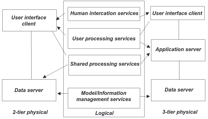
9.2 Distributing components using a multi-tier architecture model ... 35
10 Technology viewpoint: a basis for cross platform interoperability... 38
10.1 Infrastructure interoperability and the technology viewpoint... 38
10.2 A need for multiple platform-specific specifications ... 39
10.3 Conformance between Platform-neutral and Platform-specific service specifications ... 39
10.4 From platform-neutral to platform-specific specifications... 40
Annex A (normative) Conformance ... 41
A.1 Conformance Requirements ... 41
A.2 Service architecture test module ... 41
A.2.1 Geographic service types definition ... 41
A.2.2 Service chain ... 41
A.2.3 Service chaining patterns ... 42
A.2.4 Simple service architecture ... 42
A.3 Service specification test module ... 42
A.3.1 Introduction ... 42
A.3.2 Platform-neutral service specifications... 42
A.3.3 Platform-specific service specifications ... 43
A.3.4 Platform-specific service implementations... 44
Annex B (informative) Example user scenarios ... 45
B.1 Example 1 - Service Chaining for Remote Sensed Data ... 45
B.1.1 Summary ... 45
B.1.2 Precondition ... 45
B.1.3 Detailed Steps... 45
B.1.4 Post Conditions... 46
B.1.5 Service Chain Directed Acyclic Graph... 46
B.2 Example 2 - Roadside Services ... 47
B.2.1 Summary ... 47
B.2.2 Precondition ... 47
B.2.3 Detailed Steps... 47
Annex C (normative) Data dictionary for geographic service metadata... 48
C.1 Data dictionary overview ... 48
C.1.1 Introduction ... 48
C.1.2 Attribute name/Role name... 48
C.1.3 Definition... 48
C.1.4 Obligation/Condition... 48
C.1.5 Maximum occurrence ... 49
C.1.6 Data type ... 49
C.1.7 Attribute class or target class of role ... 49
C.1.8 Prefixes to Names ... 49
C.2 Metadata data dictionaries ... 49
C.2.1 Data dictionary for MD_Identification ... 49
C.2.2 Data dictionary for SV_ServiceIdentification ... 51
C.2.3 Data dictionary for SV_OperationMetadata... 52
C.2.4 Data dictionary for SV_ServiceProvider ... 52
C.2.5 Data dictionary for MD_DataIdentification ... 53
C.2.6 Data dictionary for SV_OperationChainMetadata... 53
C.2.7 Data dictionary for SV_Parameter ... 53
Annex D (informative) Mapping to Distributed Computing Platforms ... 55
D.1 From platform-neutral to platform-specific specifications... 55
D.2 UML constructs used in the ISO 19100 series of standards ... 57
D.3 Platform-neutral technology model... 58
D.4 Mapping to CORBA-specific service specifications ... 59
D.5 Mapping to MS COM-specific service specifications ... 61
D.6 Mapping to J2EE/EJB-specific service specifications ... 62
Bibliography ... 67
Figures
Figure 1 — Abstract and Implementation Service Specifications ... 6Figure 2 — Interoperability... 7
Figure 3 — Service definition relationships... 9
Figure 4 — Chain ... 11
Figure 5 — Transparent chaining ... 15
Figure 6 — Translucent chaining ... 16
Figure 7 — Opaque chaining ... 18
Figure 8 — Services and service metadata ... 20
Figure 9 — Service metadata class diagram ... 21
Figure 10 — Logical multi-tiered architecture ... 35
Figure 11 — From Logical 4-tier to Physical 2-tier or 3-tier architecture ... 36
Figure 12 — Mapping logical 4 tier to thick and thin clients... 37
Figure 13 — Mapping from platform independent UML models ... 38
Figure 14 — Technology viewpoint model of the Interoperability Reference Model ... 39
Figure 15 — From platform-neutral abstract specifications to multiple platform-specific implementations... 40
Figure B.1 — DAG for Service Chaining Scenario Example ... 46
Figure B.2 — Roadside service scenario... 47
Figure D.1 — From platform-neutral to specific models through UML mappings... 56
Figure D.2 — From platform-neutral to platform-specific specifications... 57
Figure D.3 — Platform-neutral abstract technology model... 58
Figure D.4 — CORBA Technologies related to Abstract Architecture model... 59
Figure D.5 — MS DNA/COM Model ... 61
Figure D.6 — J2EE/EJB model... 62
Figure D.7 — EXPRESS/SDAI model ... 64
Foreword
ISO (the International Organization for Standardization) is a worldwide federation of national standards bodies (ISO member bodies). The work of preparing International Standards is normally carried out through ISO technical committees. Each member body interested in a subject for which a technical committee has been established has the right to be represented on that committee. International organizations, governmental and non-governmental, in liaison with ISO, also take part in the work. ISO collaborates closely with the International Electrotechnical Commission (IEC) on all matters of electrotechnical standardization.
International Standards are drafted in accordance with the rules given in the ISO/IEC Directives, Part 3.
The main task of technical committees is to prepare International Standards. Draft International Standards adopted by the technical committees are circulated to the member bodies for voting. Publication as an International Standard requires approval by at least 75 % of the member bodies casting a vote.
Attention is drawn to the possibility that some of the elements of this International Standard may be the subject of patent rights. ISO shall not be held responsible for identifying any or all such patent rights.
ISO 19119 was prepared by Technical Committee ISO/TC 211, Geographic information/Geomatics.
This work item has been harmonized with Topic 12 of the OGC Abstract Specification [3], The Open GIS Service Architecture, Version 2. Ongoing work in CEN/TC 287, OMG, ODMG and other activities has been taken into account.
Introduction
The widespread application of computers and use of geographic information systems (GIS) have led to the increased analysis of geographic data within multiple disciplines. Based on advances in information technology, society’s reliance on such data is growing. Geographic datasets are increasingly being shared, exchanged, and used for purposes other than their producers’ intended ones. GIS, remote sensing, automated mapping and facilities management (AM/FM), traffic analysis, geopositioning systems, and other technologies for Geographic Information (GI) are entering a period of radical integration.
This International Standard provides a framework for developers to create software that enables users to access and process geographic data from a variety of sources across a generic computing interface within an open information technology environment.
“a framework for developers” means this International Standard is based on a comprehensive, common (i.e., formed by consensus for general use) plan for interoperable geoprocessing.
“access and process” means that geodata users can query remote databases and control remote processing resources, and also take advantage of other distributed computing technologies such as software delivered to the user's local environment from a remote environment for temporary use.
“from a variety of sources” means that users will have access to data acquired in a variety of ways and stored in a wide variety of relational and non-relational databases.
“across a generic computing interface” means that ISO 19119 interfaces provide reliable communication between otherwise disparate software resources that are equipped to use these interfaces.
Geographic information — Services
1 Scope
The scope of this International Standard is as follows:
Identification and definition of the architecture patterns for service interfaces used for geographic information and definition of the relationships to the Open Systems Environment model.
This International Standard presents a geographic services taxonomy and a list of example geographic services placed in the services taxonomy.
This International Standard prescribes how to create a platform-neutral service specification, and how to derive platform-specific service specifications that are conformant with this.
This International Standard provides guidelines for the selection and specification of geographic services from both platform-neutral and platform-specific perspectives.
2 Conformance
Any product claiming conformance with this International Standard shall pass all the requirements described in the abstract test suite given in Annex A.
NOTE The definition of an abstract test suite appears in ISO 19105.
3 Normative
references
The following standards contain provisions that, through reference in the text, constitute provisions of this International Standard. At the time of publication, the editions indicated were valid. All standards are subject to revision, and parties to agreements based on this International Standard are encouraged to investigate the possibility of applying the most recent editions of the standards shown below. Members of IEC and ISO maintain registers of currently valid International Standards.
ISO/IEC 10746-1:1998, Information technology — Open Distributed Processing — Reference model: Overview
ISO/IEC 10746-2:1996, Information technology — Open Distributed Processing — Reference model: Foundations
ISO/IEC TR 14252:1996 Information technology — Guide to the POSIX Open System Environment (OSE)
ISO/TS 19103: —1), Geographic information — Conceptual schema language
ISO 19115:—1), Geographic information — Metadata
4 Terms and definitions
For the purposes of this International Standard, the following terms and definitions apply.
4.1.1 service
distinct part of the functionality that is provided by an entity through interfaces [ISO/IEC TR 14252]
NOTE See 6.2 for a discussion of service
4.1.2 interface
named set of operations that characterize the behaviour of an entity
NOTE See 6.2 for a discussion of interface
4.1.3 operation
specification of a transformation or query that an object may be called to execute
NOTE An operation has a name and a list of parameters.
NOTE See 6.2 for a discussion of operation
4.1.4
interoperability
capability to communicate, execute programs, or transfer data among various functional units in a manner that requires the user to have little or no knowledge of the unique characteristics of those units [ISO 2382-1]
4.1.5
service chain
sequence of services where, for each adjacent pair of services, occurrence of the first action is necessary for the occurrence of the second action
4.1.6 workflow
automation of a business process, in whole or part, during which documents, information or tasks are passed from one participant to another for action, according to a set of procedural rules
4.1.7
viewpoint (on a system)
form of abstraction achieved using a selected set of architectural concepts and structuring rules, in order to focus on particular concerns within a system [ISO/IEC 10746-2]
4.1.8
enterprise viewpoint
viewpoint on an ODP system and its environment that focuses on the purpose, scope and policies for that system [ISO/IEC 10746-2]
4.1.9
information viewpoint
viewpoint on an ODP system and its environment that focuses on the semantics of information and information processing [ISO/IEC 10746-2]
4.1.10
computational viewpoint
4.1.11
engineering viewpoint
viewpoint on an ODP system and its environment that focuses on the mechanisms and functions required to support distributed interaction between objects in the system [ISO/IEC 10746-2]
4.1.12
technology viewpoint
viewpoint on an ODP system and its environment that focuses on the choice of technology in that system [ISO/IEC 10746-2]
4.1.13
distribution transparency
property of hiding from a particular user the potential behaviour of some parts of a distributed system [ISO/IEC 10746-2]
NOTE Distribution transparencies enable complexities associated with system distribution to be hidden from applications where they are irrelevant to their purpose.
5 Abbreviated
terms
For the purposes of this document the following abbreviations apply.
API Application Programming Interface
CORBA Common Object Request Broker Architecture
DAG Directed Acyclic Graph
DCP Distributed Computing Platform
DEM Digital Elevation Model
EDOC Enterprise Distributed Object Computing
EJB Enterprise Java Beans
EOSE Extended Open Systems Environment Model
GIOP General Inter-ORB Protocol
HTI Human Technology Interface
IDL Interface Definition Language
HIS Information Technology Human Interaction Service
IIOP Internet Inter-ORB Protocol
IT Information Technology
J2EE Java 2 Enterprise Edition with EJB
JDBC Java Data Base Connectivity
JIM Java IDL
JSP Java Server Pages
MTS Microsoft Transaction Server
OCL Object Constraint Language
ODBC Open Database Connectivity
ODP Open Distributed Processing (see RM-ODP)
OGC Open GIS Consortium
ORB Object Request Broker
OSE Open Systems Environment
RMI Remote Method Invocation
RM-ODP Reference Model of Open Distributed Processing (ISO/IEC 10746)
RPC Remote Procedure Call
SOAP Simple Object Access Protocol
SOF Service Organizer Folder
SQL Structured Query Language
UML Unified Modelling Language
XML Extensible Markup Language
XML RDF XML Resource Description Framework
6 Overview of geographic services architecture
6.1 Purpose and justification
The definition of service includes a variety of applications with different levels of functionality to access and use geographic information. While specialized services will appropriately remain an area for proprietary products, standardization of the interfaces to those services allows interoperability between proprietary products. Geographic information system and software developers will use these standards to provide general and specialized services that can be used for all geographic information. The approach of this standard is integrated with the approaches being developed within the more general world of information technology.
The geographic services architecture specified in this International Standard has been developed to meet the following purposes:
provide an abstract framework to allow coordinated development of specific services,
enable interoperable data services through interface standardization,
support development of a service catalogue through the definition of service metadata,
allow separation of data instances & service instances,
enable use of one provider's service on another provider's data, and
define an abstract framework which can be implemented in multiple ways.
This International Standard extends the architectural reference model defined in ISO 19101. ISO 19101 defines an Extended Open Systems Environment (EOSE) model for geographic services.
6.2 Interoperability reference model – based on ISO RM-ODP
multiple viewpoints. Furthermore, architecture helps to ensure that each view will be consistent with the requirements and with the other views.
Table 1 shows how the RM-ODP viewpoints are utilized in this International Standard.
Table 1 — Use of RM-ODP viewpoints in this Standard
Viewpoint Name
Definition of RM-ODP Viewpoint [ISO/IEC 10746-1]
How viewpoint is addressed in this Standard
Enterprise viewpoint
A viewpoint on an ODP system and its
environment that focuses on the purpose, scope and policies for that system.
Available in other parts of 19100 series of standards, e.g., Reference model (ISO 19101)
Computational viewpoint
A viewpoint on an ODP system and its environment that enables distribution through functional decomposition of the system into objects which interact at interfaces.
See clause 7 - Computational viewpoint
Information viewpoint
A viewpoint on an ODP system and its environment that focuses on the semantics of information and information processing.
See clause 8 - Information viewpoint
Engineering viewpoint
A viewpoint on an ODP system and its
environment that focuses on the mechanisms and functions required to support distributed
interaction between objects in the system.
See clause 9 - Engineering viewpoint
Technology viewpoint
A viewpoint on an ODP system and its environment that focuses on the choice of technology in that system.
See clause 10 - Technology viewpoint. Also to be addressed by platform-specific service specifications
The enterprise viewpoint is concerned with the purpose, scope and policies of an enterprise or business and how they relate to the specified system or service. An enterprise specification of a service is a model of that service and the environment with which the service interacts. It covers the role of the service in the business and the human user roles and business policies related to the service.
The computational viewpoint is concerned with the interaction patterns between the components (services) of the system, described through their interfaces. A computational specification of a service is a model of the service interface seen from a client, and the potential set of other services that this service requires to have available, with the interacting services described as sources and sinks of information.
The information viewpoint is concerned with the semantics of information and information processing. An information specification of an ODP system is a model of the information that it holds and of the information processing that it carries out.
The engineering viewpoint is concerned with the design of distribution-oriented aspects, i.e., the infrastructure required to support distribution. An engineering specification of an ODP system defines a networked computing infrastructure that supports the system structure defined in the computational specification and provides the distribution transparencies that it defines. ODP defines the following distribution transparencies: access, failure, location, migration, relocation, replication, persistence and transaction. Security may also be a mechanism.
The technology viewpoint describes the implementation of the ODP system in terms of a configuration of technology objects representing the hardware and software components of the implementation. It is constrained by cost and availability of technology objects (hardware and software products) that would satisfy this specification. These may conform to platform-specific standards which are effectively templates for technology objects.
viewpoints, this International Standard defines how a particular service shall be mapped on to an implementation technology such as SQL-3/ODBC, ODMG, CORBA, DCOM/OLE, Internet or similar.
6.3 Service Abstraction
This International Standard defines the approach to defining services that shall be used in the ISO 19100 series of standards. Figure 1 defines the relationship between the various types of service specifications. SV_ServiceSpecification defines services without reference to the type of specification or to its implementation. A SV_PlatformNeutralServiceSpecification provides the abstract definition of a specific type of service but does not specify the implementation of the service. Service types are given in the geographic service taxonomy in 8.3. SV_PlatformSpecificServiceSpecification defines the implementation of a specific type of service. There may be multiple platform-specific specifications for a single platform-neutral specification. SV_service is an implementation of a service. The requirements for these specifications are addressed in this International Standard, in particular in clause 10.
SV_ServiceSpecification
+ name : CharacterString + opModel : SV_OperationModel
SV_PlatformNeutralServiceSpecifiation + serviceType : SV_ServiceType
1
type : SV_ServiceType
1
+typeSpec 1 +abstSpec
SV_PlatformSpecificServiceSpecification + DCP : DCPList
1 name : DCPList
1
+implSpec +typeSpec
SV_Service 0..n
1..n +specification
+implementation
Figure 1 — Abstract and Implementation Service Specifications
6.4 Interoperability
Interoperability is the capability to communicate, execute programs, or transfer data among various functional units in a manner that requires the user to have little or no knowledge of the unique characteristics of those units.
Y X
R
S
Figure 2 — Interoperability
This means that two interoperable systems can interact jointly to execute tasks. For the geographic domain, the following description of the term “geographic interoperability” is applicable:
“Geographic interoperability” is the ability of information systems to 1) freely exchange all kinds of spatial information about the Earth and about the objects and phenomena on, above, and below the Earth’s surface; and 2) cooperatively, over networks, run software capable of manipulating such information.
The ODP viewpoint abstraction provides a framework for describing a system at several abstraction levels. In this International Standard, interoperability is viewed in terms of the different abstraction levels provided by RM-ODP. This International Standard focuses, from different viewpoints, on how semantic and syntactic interoperability of geographic metadata and geographic data can be supported.
When two different organizations have independently developed distributed systems, each can be described according to the RM-ODP viewpoints, and interoperability between the systems can be discussed with respect to each of the five RM-ODP viewpoints.
For each interoperability aspect, a distinction is made between syntactical interoperability and semantic interoperability. Syntactical interoperability assures that there is a technical connection, i.e., that the data can be transferred between systems. Semantic interoperability assures that the content is understood in the same way in both systems, including by those humans interacting with the systems in a given context.
6.5 Use of other geographic information standards in service specifications
A service specification shall include relevant information models from the appropriate geographic information standards in the ISO 19100 series. The corresponding UML models shall be used in the definition of the service interfaces as appropriate.
6.6 Architecture Patterns
An architecture pattern expresses a fundamental structural organization or schema for software services. It identifies a set of services, specifies their responsibilities, and includes rules and guidelines for organizing the relationships between them. Services, implemented by classes and objects, may use design patterns but this level of detail is outside the scope of this International Standard.
Table 2 — Elements of a Pattern
Element of a Pattern Description of Element
Name The name is a word or short meaningful phrase that describes the pattern. The name is extremely important, since it is used to reduce communication overhead. Nicknames or synonyms may be provided.
Problem This is a statement of the problem which describes its intent, goals and objectives it wants to reach within the given context and forces. Often the forces oppose these objectives as well as each other.
Context Context defines the preconditions under which the problem and its solution seem to recur, and for which the solution is desirable. This defines the pattern's applicability. It can be thought of as the initial configuration of the system before the pattern is applied.
Forces The forces are considerations that must be weighed to reach the best solution. Forces define the kinds of trade-offs that must be considered in the presence of the tension or dissonance they create. The forces answer the question, "Why is this a hard problem?"
Structure Structure defines the static relationships and dynamic rules describing how to realize the desired outcome. The structure description is accomplished through a collaboration diagram.
7 Computational
viewpoint:
a basis for service chaining
7.1 Component and service interoperability and the computational viewpoint
The computational viewpoint is concerned with describing the entities of a distributed system independent of implementation and semantic content. It describes the interaction patterns between the entities and their interfaces. To be able to interoperate from the computational viewpoints two systems must be interfaces and services interoperable. Two systems are interface and services interoperable if they agree on the set of services offered by the entities of the two systems and the interfaces to these entities. If standardized interfaces are defined, the entities of one system will be able to request services from entities in another system.
The computational viewpoint clause provides the following:
defines the concepts of services, interfaces and operations and the relations between these concepts;
provides an approach to physical distribution of services using an n-tier architecture;
defines a model for combining services in a dependent series to achieve larger tasks – service chaining; and
defines a service metadata model to support service discovery through a service catalogue.
7.2 Services, interfaces and operations
Definitions and relationships of several terms are provided in this clause. These terms are used extensively in this International Standard:
Service: distinct part of the functionality that is provided by an entity through interfaces.
Interface: named set of operations that characterize the behaviour of an entity.
These terms are related to each other as depicted in Figure 3. Figure 3 shows that services are specified by set of interfaces that are a set of operations. Interfaces are implemented as ports that make services available to users.
SV_PortSpecification + binding : DCPList + address : URI
SV_Service
SV_Port SV_ServiceSpecification
+ name : CharacterString + opModel : SV_OperationModel
SV_Interface + typeName : TypeName
1..n 1..n
SV_Operation
+ operationName : MemberName operationName : MemberName
1..n
1 +interface
+operation
Figure 3 — Service definition relationships
The aggregation of interfaces in a service shall be for the purpose of defining functionality of value to the users. Users in this context are either software agents or human users. A service provides functionality that adds value. The value is apparent to the user who invoked the service.
The aggregation of operations in an interface, and the definition of interface, shall be for the purpose of software reusability. Interfaces shall be defined in order to be reusable for multiple service types. The syntax of an interface may be reused with multiple services with different semantics.
Services of multiple types may be aggregated. The service types shall be defined consistent with the service taxonomy of 8.3. When a service provides functionally beyond that of a single category in the service taxonomy it shall be an aggregate service. Services chaining results in aggregate services as defined in 7.3.5.
Interfaces are abstract specifications separate from the concrete deployment or data format bindings. The specification of an interface shall include a static portion that includes definition of the operations. The specification of an interface shall include a dynamic portion that includes any restrictions on the order of invoking the operations.
An implementation of an interface is a port. The implementation includes implementation of the platform-specific specification and a method to identify the service, e.g., an address.
An implementation of a service may be associated with a specific dataset or it may be a service that can be used to operate on multiple, unspecified datasets. The first case is referred to as tightly-coupled service. The second case is referred to as a loosely-coupled service. (See 7.4.1).
7.3 Service chaining
7.3.1 Introduction to Service Chaining
7.3 defines a model for combining services in a dependent series to achieve larger tasks. 7.3 addresses the syntactic issues of service chaining, e.g., data structure of a chain. Semantic issues associated with service chaining are addressed in 8.6, e.g., does a specific chain produce a valid result? Examples of service chaining are provided in Annex B.
This International Standard enables users to combine data and services in ways that are not pre-defined by the data or service providers. This level of data/service interoperability will be achieved in stages. At first service catalogues will hold entries with tight data/service binding. Eventually the infrastructure will be available for a user to determine which data can be acted on by a loosely coupled service. This capability will be enabled by the infrastructure of the larger domain of IT.
Based on the ODP definition of Chain, a Service Chain is defined as a sequence of services where, for each adjacent pair of services, occurrence of the first action is necessary for the occurrence of the second action.
7.3.2 Anatomy of a service chain
7.3.2.1 Chains as directed graphs
The action of making the input of one service dependent upon another service leads to treating service chains as directed graphs, where each service is a node in the graph and references to service interactions form the edges. In some cases the directed graph structure is implicit. In other cases it is necessary to make the notion of a processing graph explicit and allow such graphs to be considered as entities in their own right. Explicit representation of a service chain allows the chain to be visually represented and passed to a chain execution service, e.g., workflow service.
A node in the directed graph is a representation of the service. When explicitly formed into a data structure, a service node contains two types of information: parameters and sources. Parameters in a service node provide the configurations of the service for the particular chain in which the service class is being used. Sources in a service node indicate the sources of input data to the node.
The arcs of a directed graph representing a service chain can be of several types. These types of arcs are detailed below as service interactions.
A key aspect of a directed graph is whether it is cyclic or acyclic. The case of directed graphs without loops, i.e. acyclic, is simpler. In some applications an iterative approach is needed, therefore the chain will be cyclic with conditions in the control function to address convergence.
Chains can be considered templates or as immutable graphs. A template is a directed graph which defines the chain based on abstract classes including identification of each service type. A template can be instantiated as an immutable graph at which time the service instances are fixed.
Additional elements characterizing a service chain:
Parallel vs. serial chains: does the directed graph have parallel paths based on branches or are only serial chains permitted? Potential branch types include: if/else, merge, switch, and trigger
Iteration: does a node in the directed graph operate as an iteration, e.g., while and count loops?
Parameters in nodes: do the description of nodes in the directed graph contain parameters that can be changed?
Variations in control design pattern: pull processing vs. push processing
7.3.2.2 UML modelling of a chain
Figure 4 provides a UML model of a chain.
SV_OperationChain + name : CharacterString
+ description[0,1] : CharacterString SV_Operation
(from Service Model) + operationName : MemberName
1..n
+operation {ordered}
+chain Chaining
0..n +dependsOn
Dependencies
Figure 4 — Chain
In accordance with ISO/TS 19103, the modelling of directed graphs for service chains shall be done using the Unified Modeling Language (UML) activity graphs. An activity graph represents the states of executing a service chain. Table 3 identifies the elements of an activity graph.
Table 3 — UML Activity Graph entities
Element of an UML Activity Graph Description for Service Chaining
Activity State A state that represents the execution of a service, typically triggered by the invocation of an operation.
Transition A relationship between two states. A transition indicates that specified Actions are performed in the first state and the second state is entered when a specified Event occurs and specified Guard Conditions are satisfied.
Branch/Merge The beginning/end of alternative threads in an activity graph
Fork/Join The beginning/end of concurrent threads in an activity graph
Signal An asynchronous communication between services
7.3.3 Services organizer folder
Services are of many types as indicated in 8.3. Only a subset of available services is applicable to a specific situation, e.g., image analysis. A service organizer folder is an aid for users in finding services applicable to their situation. A user may construct a SOF and then make that SOF available to other users performing tasks in a similar situation.
A services organizer folder (SOF) is a data structure that shall contain references to a set of services that are applicable to a given situation. The SOF need not contain service chains but may contain just individual services.
7.3.4 Services to enable service chaining
Table 4 — Services to enable service chaining
Services needed to enable service chaining
OSE Categories Generic IT Services Geographic services
Human interaction services • service-centric service for defining, controlling and statusing service chains
• catalogue-centric service that views and browses metadata about services
• catalogue-centric service that locates, browses, and manages metadata about spatial data
• spatial-centric service for editing, displaying, querying, and analyzing map data
• Calculation-centric service allowing viewing and manipulation of geographic data using a spreadsheet format.
Workflow/Task services • Workflow enactment service to define, invoke, status and control service chaining. (interaction with other Workflow services, optional)
• Service chain validation service
• Resource reservation and co-allocation mechanism for both storage system and other resources such as networks, to support the end-to-end performance guarantee required for predictable transfer.
Processing services • Geographic processing services (See clause
8)
Model/Information management services
• Service instance metadata catalogue - with discovery and management sub-services
• Service type registry - with discovery and management sub-services
• Brokering
• Mediation
• Geographic Dataset instance
• Geographic metadata catalogue - with discovery, access and management sub-services.
System management service • authorization and authentication
• payment methods
• privacy of client
• Performance measurement and estimation techniques for key resources involved in data grid operation, including storage systems, networks, and computer
• Instrumentation services that enable the end-to-end instrumentation of storage transfer and other operation
Communication services • Messaging mechanisms
• Large data object transfer
• Remote file and executable management: provides access to secondary storage as if it were local.
• Format conversions
• Geographic format conversions
7.3.5 Architecture patterns for service chaining
7.3.5.1 Introduction
There are many options for the allocation of service chaining services to components. Different allocation approaches reflect different priorities for different applications: user in the loop vs. user supervision. To demonstrate the breadth of the trade space defined by this variation, three design patterns are offered that vary the allocation of the control function:
• User defined (transparent) chaining: the Human user manages the workflow.
• Workflow-managed (translucent) chaining: in which the Human user invokes a Workflow Management service that controls the chain and the user is aware of the individual services.
• Aggregate service (opaque): in which the user invokes a service that carries out the chain, with the user having no awareness of the individual services.
In addition to the difference in visibility of the services to the user, a key distinction between these patterns is the difference in control. In transparent chaining the control is exclusively with the user. In translucent, a workflow service is present which controls the chain execution, perhaps with oversight by the human. In the aggregate pattern, the aggregate service exclusively performs the control function with no visibility by the user.
7.3.5.2 User defined (transparent) chaining
7.3.5.2.1 Name
As the name implies, the user defines and controls the order of execution of the individual services. Details of the services are not hidden from the user, hence, the alias for this pattern is Transparent Chaining.
7.3.5.2.2 Problem
In this pattern the user is knowledgeable of how services can be combined. The user discovers and evaluates the available services, determine their fitness to the need, determines a valid sequence of services, and controls the chaining. This pattern anticipates a knowledgeable user. The user is provided information sufficient to make the control decisions.
7.3.5.2.3 Context
The user knows of a service catalogue in order to discover services of interest. A specific chain does not exist before the user begins. The user has the ability to define a valid chain and/or be able to modify the implied chain if there are failures in execution.
7.3.5.2.4 Forces
The user must be able to design an efficient chain that will execute. The inputs and outputs of the individual services must be compatible, or an intervening service must be added, e.g., format translation. These patterns assume that each service has sufficient resources to run efficiently, but the user may need to choose services based on network considerations, e.g., network bandwidth, security, authorization. The semantic correctness of the chain is judged by the user; issues such as when data is re-gridded in a chain will affect the validity of the results. A user may iterate a chain until an acceptable result is achieved, resulting in a chain that can be saved and used by others, perhaps using the workflow chaining pattern.
7.3.5.2.5 Structure
The User Defined Chaining Architecture Pattern is shown in Figure 5.
Client
Catalogue Service
Service Service
Service
1. Search Request
2. Search Results
5a. Invoke Service
4a. Invoke Service 3. Invoke Service
4b. Request Input 5b. Request Input
5c. Request Input
Figure 5 — Transparent chaining
Table 5 — Description of steps in Figure 5
Step 1. Search Request A human uses a client to send a search request (or series of searches) to a catalogue service. The catalogue service provides queries on service metadata.
Step 2. Search Results Catalogue Service returns metadata about services of interest to the user. For this example the user has found three services which will be chained.
Step 3. Invoke Service User invokes a service using the client, causing a result to be available for a subsequent service
Step 4a. Invoke Service Step 4b. Request Input
User invokes a second service using the client. The request includes a reference to the results from the previous step. The service creates a result that is available for the next service.
Step 5a. Invoke Service Step 5b. Request Input Step 5c. Request Input
User invokes a third service using the client. The request includes references to the two previous services. This third service returns a result to the client.
7.3.5.3 Workflow-Managed (translucent) chaining
7.3.5.3.1 Name
As the name implies in this pattern the execution of the chain is managed by a workflow service (or multiple workflow services). The user’s involvement in the steps of the chain is mostly one of watching the chain execute the individual services that are apparent to the user, hence the alias of translucent chaining. A key distinction for this pattern is the existence of a defined chain prior to the user executing the pattern.
7.3.5.3.2 Problem
7.3.5.3.3 Context
The user knows of a workflow service and has selected a chain of interest. The user interacts with the workflow service to execute the chain including providing parameters specific to the data instances of interest to the user.
7.3.5.3.4 Forces
To reduce the user’s workload, the workflow service handles details of the distributed computing aspects of executing the chain. Although the predefined chain is assumed to have a degree of semantic validity, by evaluating interim results, the user can evaluate the semantic validity of the specific instance of this processing. For example for a service that includes an iterative algorithm, the user may need to judge if convergence to a sufficient degree of accuracy has been achieved.
7.3.5.3.5 Structure
The Workflow-Managed (translucent) chaining architecture pattern is shown in Figure 6.
NOTE: There may be multiple workflow services. If there is more than one the workflow services must coordinate to carry out the predefined chain. In the extreme case, each service in the chain contains a workflow service and the chain is passed along with the service results. The unique features of the translucent pattern are the existence of a predefined chain and the user’s awareness of the chain.
Client
Workflow Service
Service Service
Service 1. Invoke a chain
5. Chain Results
2a. Invoke Service
4a. Invoke Service
3b. Request Input 4b. Request Input
4c. Request Input 4d. Service Status
2b. Service Status
3c. Service Status
3a. Invoke Service
Table 6 — Description of steps in Figure 6
Step 1. Invoke a Chain A human uses a client to request that a workflow service execute a chain. The user may be allowed to modify some aspects of the chain prior to execution.
Step 2a. Invoke service Step 2b. Service status
The workflow service determines the services in the chain and invokes the first service. The service informs the workflow service of the completion of the task. Status of the service may be provided directly to the client. The client may stop the workflow.
Step 3a. Invoke service Step 3b. Request input Step 3c. Service status
Upon notification of completion of the first service, the workflow service determines the next service in the chain and invokes it. The second service requests results from the first service. The service informs the workflow service of the completion of the task. Status of the service may be provided directly to the client. The client may stop the workflow.
Step 4a. Invoke service Step 4b. Request input Step 4c. Request input Step 4d. Service status
Upon notification of completion of the second service, the workflow service determines the next service in the chain and invokes it. The third service requests results from the first and second services. The service informs the workflow service of the completion of the task. Status of the service may be provided directly to the client. The client may stop the workflow.
Step 5. Chain results Upon notification of completion of the last service, the workflow service informs the client of the completion of the chain.
7.3.5.4 Aggregate Service (opaque-chaining)
7.3.5.4.1 Name
As the name implies in this pattern the services appear as a single service which handles all coordination of the individuals services behind the aggregate service. The user has no awareness that there is a set of services behind the aggregate, hence the alias of opaque chaining.
7.3.5.4.2 Problem
In this pattern the user relies on an aggregate service to execute a predefined chain of services. The user has discovered the aggregate service and may have no knowledge of how the aggregate accomplishes the service. The user may need to provide parameters particular to the specific instance, but relies on the aggregate service to carry out the chain.
7.3.5.4.3 Context
The user knows of an aggregate service perhaps not knowing that a chain of services implements the aggregate. The user interacts with the aggregate service to execute the chain including providing parameters specific to the data instances of interest to the user.
7.3.5.4.4 Forces
To reduce the user’s workload, the aggregate service handles all details of the multi-service aspects of executing the chain. Although the aggregate service chain is assumed to have a degree of semantic validity, by evaluating interim results, the user can evaluate the semantic validity of the specific instance of this processing. For example for a service that includes an iterative algorithm, the user may need to judge if a sufficient degree of convergence has been achieved. These intermediate results need not reveal the underlying services.
7.3.5.4.5 Structure
Client
Aggregate Service
Service Service
Service
1. Invoke Service 5. Service Results
4a. Invoke Service
3a. Invoke Service 2. Invoke Service
3b. Request Input 4b. Request Input
4c. Request Input
Figure 7 — Opaque chaining
Table 7 — Description of steps in Figure 7
Step 1. Invoke a service A human uses a client to request that an aggregate service execute a chain. The user may have no knowledge that the service is implemented using a chain of services.
Step 2a. Invoke service The aggregate service determines the services in the chain and invokes the first service. The service informs the aggregate service of the completion of the task.
Step 3a. Invoke service Step 3b. Request input
Upon notification of completion of the first service, the aggregate service determines the next service in the chain and invokes it. The second service requests results from the first service. The service informs the aggregate service of the completion of the task.
Step 4a. Invoke service Step 4b. Request input Step 4c. Request input
Upon notification of completion of the second service, the aggregate service determines the next service in the chain and invokes it. The third service requests results from the first and second services. The service informs the aggregate service of the completion of the task.
Step 5. Chain results Upon notification of completion of the last service, the aggregate service informs the client of the completion of the chain.
7.3.6 Variations on chaining patterns
The three chaining patterns discussed above could be combined in a variety of ways.
produces valid results. Chains are then made available for wider use following the translucent pattern. Certain chains may become routinely used and an aggregate service is built as an interface.
An example need for a translucent or opaque chaining pattern occurs in decision support. The Decision-Maker is an individual using decision support aids to help make a decision. An example of decision support aids is a service chain. The Decision Support Aid Developer is an individual who “integrates” chains of services into decision support aids.
Another type of service interaction can be considered as chaining, where a user makes a request of a lead service and the lead service then invokes a secondary service, which invokes a tertiary service. Each of the services responds to the request when it has sufficient information from the underlying services. In this way there is no explicit chain but rather a chain is implied.
7.4 Service metadata
7.4.1 Introduction
Service metadata records can be managed and searched using a catalogue service as is done for dataset metadata. In order to provide a catalogue for discovering services, a schema for describing a service is needed. This section defines a metadata model for service instances. The metadata elements for a service provide sufficient information to allow a client to invoke the service based on the metadata record. In order to place the Service Metadata in context three types of entities need to be described:
Service Instance: a service instance is the service itself, hosted on a specific set of hardware and accessible over a network.
Service Metadata: a service metadata record describes a service instance including a description of the services operations and an "address" to access the specific service instance.
Service Type: in some cases a service metadata record will describe a service instance which is of a "well known type". By well-known type, it is meant that the service conforms to a published definition of a service type, i.e., a platform-specific service specification. Some clients will be able access only services of well-known type. A user could search the service metadata catalogue to find instances of a specific well-well-known service type. A service registry is defined to be the service that provides details on service types.
A service instance may be tightly-coupled with a dataset instance, or it may be un-associated with specific data instances, i.e. loosely-coupled. Loosely-coupled services may have an association with data types through the service type definition. In the tightly-coupled case, the service metadata shall describe both the service and the geographic dataset, the latter being defined in accordance with ISO 19115. Also for the tightly-coupled case, the permitted values in the SV_operations shall be constrained by the values defined by the datasets associated with the service. For the loosely-coupled case, dataset metadata need not be provided in the service metadata.
SV_ServiceIdentification + serviceType : GenericName
+ serviceTypeVersion[0..n] : CharacterString
+ accessProperties[0,1] : MD_StandardOrderProcess + restrictions[0,1] : MD_Constraints
SV_OperationMetadata + operationName : CharacterString + DCP[1..*] : DCPList
+ operationDescription[0,1] : CharacterString + invocationName[0,1] : CharacterString + connectPoint[1..*] : CI_OnlineResource
0..n
+dependsOn
Dependencies
1..n +containsOperations
SV_Operation
+ operationName : MemberName (from Service Model)
0..n
+dependsOn
Dependencies
SV_Interface
+ typeName : TypeName (from Service Model)
operationName : MemberName 1..n
1 +interface
+operation SV_ServiceSpecification
(from Service Model)
1..n 1..n
Figure 8 — Services and service metadata
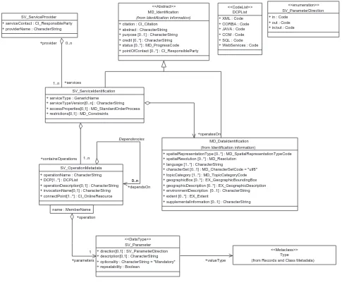
7.4.2 Service metadata main class diagram
Figure 9 provides a UML static model of service metadata for a service instance.
The structure of service metadata includes three major classes: a section of basic service metadata (SV_ServiceIdentification class) that provides a general description of the service and two sections that describe the operations (SV_OperationMetadata) and data (MD_DataIdentification) available from a particular service. The service metadata schema is defined using elements of ISO 19115.
MD_Identification
+ citation : CI_Citation + abstract : CharacterString + purpose [0..1] : CharacterString + credit [0..*] : CharacterString + status [0..*] : MD_ProgressCode + pointOfContact [0..*] : CI_ResponsibleParty
(from Identification information)
(from Records and Class Metadata) <<Metaclass>> SV_Parameter
+ direction[0,1] : SV_ParameterDirection + description[0,1] : CharacterString + optionality : CharacterString = "Mandatory" + repeatability : Boolean
<<DataType>>
+valueType MD_DataIdentification
+ spatialRepresentationType [0..*] : MD_SpatialRepresentationTypeCode + spatialResolution [0..*] : MD_Resolution
+ language [1..*] : CharacterString
+ characterSet [0..1] : MD_CharacterSetCode = "utf8" + topicCategory [1..*] : MD_TopicCategoryCode + geographicBox [0..*] : EX_GeographicBoundingBox + geographicDescription [0..*] : EX_GeographicDescription + environmentDescription [0..1] : CharacterString + extent [0..*] : EX_Extent
+ supplementalInformation [0..1] : CharacterString (from Identification information)
Figure 9 — Service metadata class diagram
7.4.3 Data dictionary for geographic service metadata
A data dictionary for geographic service metadata is provided in Annex C. The entities in Figure 9 are defined in the data dictionary.
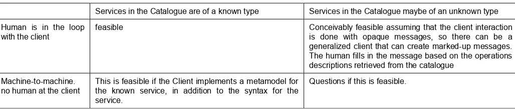
7.5 Service instance of unknown type
Table 8 — Options for well known type in service metadata
Services in the Catalogue are of a known type Services in the Catalogue maybe of an unknown type
Human is in the loop with the client
feasible Conceivably feasible assuming that the client interaction is done with opaque messages, so there can be a generalized client that can create marked-up messages. The human fills in the message based on the operations descriptions retrieved from the catalogue
Machine-to-machine. no human at the client
This is feasible if the Client implements a metamodel for the known service, in addition to the syntax for the service.
Questions if this is feasible.
7.6 Simple service architecture
The following simplifying assumptions should be considered when implementing a message-based architecture to support service chaining. Systems compliant to this set of guidelines shall be referred to as instances of simple service architectures. Systems should comply with the simple service architecture.
• Message-operations. For simplicity it is desirable to model the operations as messages. A message operation shall consist of a request and response. Requests and responses contain parameters as the payload, which is transferred in uniform manner independent of content. Simple applications are characterized by message exchange patterns such as one-way (or event), and two-way (or synchronous) request response interactions. A service specification should make such simple exchange applications as easy as possible to create and to use.
• Separation of control and data. A client controlling a service may not want the full results of the service. For example, the user may have no need for the potentially voluminous intermediate products in a service chain. Only the final result of a service chain may be needed by the client. Therefore, operations of an interface should separate the control of the service from the access to the data resulting from a service. A client should have the option of receiving just the status of an operation and separately the data should be accessible through a separate operation.
• Stateful vs. stateless service. For simplicity it is desired that a service be stateless, i.e., that a service invocation be composed of a single request-response pair with no dependence on past or future interactions. This will not always be possible. For some services, preconditions must be set and iteration may be required, then it will be necessary to model the service with a state diagram having multiple states. Transitions between the states are triggered by operations.
• Known service type. All service instances are of specific service types and the client knows the type prior to runtime. Clients shall contain software for accessing the service type prior to encountering service instances of the type in an implemented architecture. This assumption is that the client knows the service types.
• Adequate hardware. The services described in this International Standard are software implementations running on hardware hosts. This International Standard assumes that the issues of hardware hosting of the software are transparent to the user. This is the assumption that the service has adequate hardware, i.e. hardware assignment is transparent to user.
8 Information viewpoint: a basis for semantic interoperability
8.1 Information model interoperability and the information viewpoint
To be able to interoperate in the information viewpoint, two systems must be information model interoperable. To achieve information model interoperability the two systems must be both syntactically interoperable and semantically interoperable:
Syntactically interoperable – Two systems are syntactically interoperable if they use the same structure for the information that flows in the systems and is processed by the systems.
Semantically interoperable – Two systems are semantically interoperable if they have a common understanding of the semantics of the information that flows in the systems and is processed by the systems.
The common structural models being defined by the information models address syntactic interoperability. In the ISO 19100 suite of standards the models are based on a generic feature model, which allows for representation of various types of features, all having the same structure. To achieve semantic interoperability for feature types it is in addition necessary to match or make mappings between feature type definitions from feature type catalogues. The issues of such information model interoperability will not be addressed in this International Standard.
The information viewpoint in ISO RM-ODP describes the information that flows in a system and is processed by a system. It focuses on the structuring of semantic information, typically the information that will be stored in a database and communicated between the components of a system. An information model is used to describe the information viewpoint. This information model defines the structure and semantics of the information used in system by defining objects, their properties and their relationships.
The information viewpoint is also concerned with the semantics of the information processing. Each particular service will need to define its syntactical interfaces through operations and its semantics through description of the meaning of the operations and their legal sequencing. The latter can be done through pre- and post-conditions and invariants in OCL, and by UML state diagrams.
This section contains a description of a taxonomy of various services. There exist multiple possible taxonomies for services, based on various classification dimensions. The one that is used here is based on the extended OSE model. The purpose of defining a taxonomy in this International Standard is to have one way of identifying geographic extensions to various existing service types. It is not intended to be the only taxonomy to be used in the context of geographic services.
The work of identifying required services for geographic information standardization shall categorize if a needed service is GIS specific or more IT general, and which of the 6 service domains it belongs to. The processing services domain will typically contain a variety of application-area (GI) specific services.
The next sections will describe typical IT Services and then show some possible geographic services in each of the six service domains.
8.2 Extended open systems environment for geographic services
The model for the information viewpoint is provided by ISO 19101. ISO 19101 defines the Extended Open Systems Environment (EOSE) model for geographic information. The EOSE defines classes of services based on the semantic type of computation that they provide. EOSE provides the functional decomposition of the services for the geographic domain by extending the more general Open System Environment model [ISO/IEC TR 14252].
Consistent with ISO 19101, this sub-clause defines six classes of information technology services that shall be used to categorize geographic services.
Human interaction services are services for management of user interfaces, graphics, multimedia, and for presentation of compound documents.
Model/Information management services are services for management of the development, manipulation, and storage of metadata, conceptual schemas, and datasets.