Behavior of Cylindrical Steel Shells Supported
on Local Brackets
Cornelia Doerich
1and J. Michael Rotter
2Abstract: The connection of a local support to an elevated cylindrical metal silo shell is a long-standing difficult problem in shell analysis, and most designs are based on simple ideas using past experiences of successes and failures. Smaller silo structures are often supported on local brackets attached to the side of the shell, but very few investigations of the behavior or strength of such an arrangement have ever been made. This paper presents an outline description of the behavior of a cylindrical steel shell that is discretely supported on several brackets, each rigidly connected to a stiff column or floor. The linear, materially nonlinear, geometrically nonlinear, and bifurcation behaviors of the shell under these conditions are outlined. In this problem the prebuckling deformations, bifurcation mode, and plastic collapse mode are each local. This configuration presents some interesting questions concerning the relative importance of geometric nonlinearity and geometric imperfections. The problem is recommended to advanced shell analysts as a benchmark test of their analysis and interpretation techniques.
DOI:10.1061/共ASCE兲0733-9445共2008兲134:8共1269兲
CE Database subject headings:Shell structures; Supports; Silos; Tanks; Cylinders; Elastoplasticity; Collapse.
Introduction
For the storage of large quantities of particulate solids and fluids, a cylindrical shell metal structure with its axis vertical is usually the most economic. Metal silos and tanks are often required to be elevated above ground level to permit trains, trucks, or conveying systems to be placed beneath a hopper from which the solid or fluid is withdrawn. Elevated silos must be supported, and access requirements often mean that the supports must be local共either on columns or supported from an elevated floor system兲. The con-nection of such a support to a cylindrical shell is a long-standing difficult problem in shell analysis, and most designs use only past experiences of successes and failures. Smaller silo structures are often supported on local brackets attached to the side of the shell, but very few investigations of the behavior or strength of such an arrangement have ever been made.
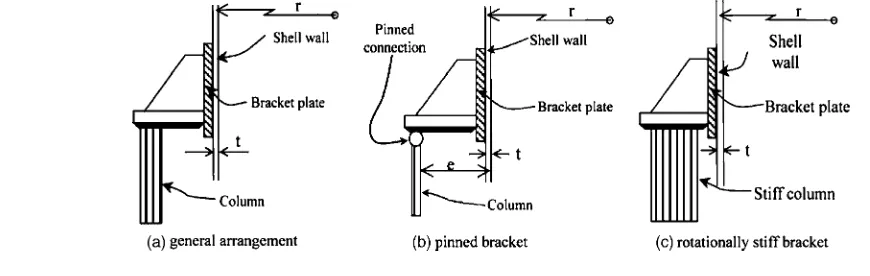
Cylindrical shells with their axis vertical have long been sup-ported at a few discrete locations around the axis 共Fig. 1兲. In larger silos, the supports are usually placed beneath a ring beam at the transition 关Fig. 1共d兲兴, but in lighter structures, direct support of the shell on a number of brackets关Fig. 1共b兲兴or by engagement of a column into the shell wall is common关Fig. 1共c兲兴. These light support structures have often been designed by engineering
judg-ment: there appear to be very few experiments that have explored their strength. With the increasing codification of consistent and comprehensive rules for design, the local support presents a sig-nificant challenge because the simpler analysis methods cannot be used to justify designs that have proved adequate in practice, but complex nonlinear calculations are usually out of the question in design evaluations of relatively inexpensive structures.
The stress analysis of a shell on discrete supports is a very challenging task. The first simple membrane theory calculations were probably performed in the 1930s by Flügge共1973兲, but the first linear shell analysis was that of Kildegaard 共1969兲, which illustrated the complexity of the problem. This analysis covered only discrete point forces on the bottom boundary of the cylinder. Where the shell is supported on engaged columns, the problem of force transmission from an axially loaded strip into a plate is relevant, and the studies of Reissner 共1940兲 and Gould et al. 共1976兲are particularly useful. A good review of early research on discretely supported cylinders was presented by Wang and Gould 共1974兲. The present study is concerned with local bracket sup-ports which were not previously considered. The most relevant earlier work was that of Bijlaard 共1955兲, who devised a linear analysis of the stresses resulting from a local patch load normal to the shell. The equivalent analyses for an axially loaded patch were presented by Li and Rotter共1996兲.
Peter共1974兲made the first linear buckling analysis, again for point forces beneath the shell, but nonlinear analyses were not possible until high powered computational tools were available. More recent computational studies by Teng and Rotter 共1990, 1992兲, Rotter et al.共1991兲, Guggenberger共1991, 1998兲, Greiner and Guggenberger 共1998兲, and Guggenberger et al.共2000兲 have only addressed local forces applied to the base boundary of a cylindrical shell.
The bracket supported shell is more widely used where the silo is within a building共Fig. 2兲. The only known strength evaluations of this arrangement共Gillie et al. 2002; Holst et al. 2002兲involved brackets that were free to rotate about a circumferential axis关Fig. 2共b兲兴, which corresponds to a weaker and less likely condition 1
Dr., Institute for Infrastructure & Environment, Univ. of Edinburgh, Mayfield Rd., Edinburgh, EH9 3JL, U.K.
2
Professor, Institute for Infrastructure & Environment, Univ. of Edin-burgh, Edinburgh EH9 3JL, U.K. 共corresponding author兲. E-mail: [email protected]
than is typically found in practice. The present study involves an extensive exploration of the elastic-plastic strength of an imper-fect cylindrical shell attached to a bracket that is restrained by the column or support against rotation关Fig. 2共c兲兴, producing a much stronger detail.
United States standards for the design of shell structures are principally oriented towards aerospace applications共Nemeth and Starnes 1998兲and unfortunately are not yet sufficiently developed to address the interpretation of advanced finite-element analyses for local support problems. The study has therefore been con-ducted within the framework of the European Standard for Shell Structures 共CEN 2006兲, which requires that the two reference strengths of the shell, the plastic collapse resistance, and the lin-ear bifurcation resistance, should both be evaluated to establish the context within which more sophisticated analyses are judged, and to provide a rapid means of producing reliable but simple design information.
Modeling of Bracket and Shell
The shell had radius r, uniform thickness t, and height H. The bracket was located at the heightHabove the base of the shell, and had heighth and width 2d 关this notation was adopted to be compatible with that used for supports at the shell base by Guggenberger et al.共2000兲兴. The bracket was treated as extremely stiff, to eliminate this aspect from the study. A notional ratio of bracket to shell thickness of tb/t= 200 was adopted, rigidly
at-tached to the shell wall, as shown in Fig. 3共a兲. Explorations of the
effect of this thickness indicated that this was sufficient to model a completely stiff bracket共Doerich 2007兲. The full cylinder was loaded by a meridional tension P per unit circumference at the lower edge 关Fig. 3共b兲兴, corresponding to the loading applied by contained fluid or solid via a hopper beneath the cylinder.
The shell was treated as ideally elastic-plastic with Young’s modulusE, Poisson’s ratio, and yield stressYwith von Mises
yield criterion. It is recognized that strain hardening will affect the strength under highly plastified conditions, but hardening was omitted from the present study for the sake of clarity and simplic-ity. It will be included in future studies. In these calculations, a cylinder with four bracket supports 共n= 4兲 was studied because this is the most common arrangement in practice.
The problem was studied using the commercial finite-element 共FE兲package ABAQUS共HKS 2003兲. The analysis used two ele-ment types, both of which are rectangular doubly curved shell elements with reduced integration and hourglass control. Most of the model used the four-noded general-purpose S4R element, but in the zone around the bracket the eight-noded thick shell element S8R was used because of its superior performance in highly plas-tified zones. To reduce the size of the computations, symmetry was exploited down the meridian through the center of the bracket, as well as down the midplane between brackets, reducing the model to one eighth of the complete shell, though sample results were verified by comparison with a full model of the entire shell. The bracket was treated as free to translate radially, but all other degrees of freedom were deemed to be restrained by the stiff column. At the top and bottom edges, no out-of-round defor-mation was permitted, simulating stiff rings.
Fig. 1.Alternative arrangements for silos on discrete supports
The mesh was verified extensively 共Doerich 2007兲 using the linear analysis 共LA兲, elastic geometrically nonlinear analysis 共GNA兲, small displacement theory elastic-plastic analysis 共MNA兲, and geometrically nonlinear elastic-plastic analysis 共GMNA兲defined in EN1993-1-6共CEN 2006兲. Particular attention was paid to the region of the corner of the bracket where a high stress concentration occurs共Doerich 2007兲. These analyses were also widely checked against those of Gillie 共2002兲 for unre-strained brackets. The finite-element mesh used, resulting from this mesh verification process, is shown in Fig. 3共c兲. Where geo-metric nonlinearity was used, the analysis included the effects of large rotations, but not large strains.
Example Bracket Support
An example bracket support is studied here to explore the char-acteristics of the behavior. This bracket was chosen to have a geometry in which there is significant interaction between elastic buckling and plasticity, even though the shell is thin, placing it clearly in the elastic-plastic buckling regime for this structure. The manner in which this choice was made is shown later.
The key parameters of this representative problem were:H/r = 4, r/t= 600, = 0.5, h/r= 0.12, h/d= 3, and n= 4, with E= 2
⫻105MPa,= 0.3, and
Y= 250 MPa. In the following analyses,
all the loads are described in a dimensionless manner, using the reference forceRREFapplied to each bracket:
RREF=cl共A/n兲=cl共2rt/n兲 共1兲 in which the classical elastic critical buckling stresscl for uni-form axial compression is given by
cl= 0.605Et/r 共2兲
The forceRREFis used to normalize all the strength calculations. This reference load corresponds to the classical elastic critical stress for uniform axial compression being applied in tension around the full shell circumference at its lower edge.
In the following, the results of the different analyses defined by in EN1993-1-6共CEN 2006兲are shown. These begin with the reference analyses of LA, linear bifurcation analysis共LBA兲, and plastic reference load 共MNA兲, and are followed by GNA and
GMNA, and analyses including explicitly modeled imperfections 共GMNIA兲. The role of each of these different analyses was de-scribed by Rotter共1998兲.
Linear Elastic Analysis
The simplest treatment of this problem is a linear elastic analysis. It is useful to study the pattern of load transfer from the tension near the shell base into the bracket, in preparation for an under-standing of the behavior found later in other analyses. In simple terms, one might expect that the vertical tension from the load on the base circumference关Fig. 3共b兲兴would be fed into the base of the bracket, perhaps with some shear transfer onto the side of the bracket. The first images worthy of study are therefore the axial membrane stress pattern and the membrane shear pattern in the shell.
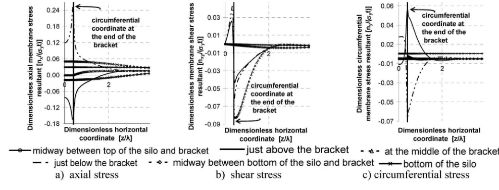
The bracket causes an inward deformation of the shell for a significant height above it, leading to inward bending in both the circumferential and meridional directions关Fig. 4共a兲兴. Further, the wall becomes flatter in this region, which is later seen to have a detrimental effect on the buckling strength. Fig. 5共a兲 shows the axial membrane stress on horizontal lines at several different lev-els in the shell. At the bottom, the load is applied and there is the Fig. 3.Dimensions and finite-element model
expected uniform axial tension. Half way between the base and the bracket, elevated tensile stresses develop towards the bracket meridian, with a corresponding decrease away from the bracket meridian. Just below the bracket, high tensile stresses focus into the bracket, with a distribution similar to that of a rigid footing on an elastic half space共Timoshenko and Goodier 1970兲. Extensive studies were undertaken of mesh sensitivity in this region, par-ticularly for the nonlinear analyses reported later共Doerich 2007兲. A strong peak can be seen at the bracket corner, but tensile stresses also continue in the shell away from the bracket meridian, ensuring that most of the load共in this example 70%兲bypasses the bracket to induce shear and compression in the shell above it. In this example, 47% of the load is transferred in shear into the side of the bracket关Fig. 5共b兲兴with a peak in membrane shear at mid-height of the bracket. Above the bracket, load共here 23%兲is trans-ferred by compression into the top of the bracket关Fig. 5共a兲兴, with a similar high peak to that below the bracket associated with the bracket corner. It is clear that the corners of the bracket represent points of strong stress concentration, and that local plasticity will affect the behavior here quite strongly, augmented by strain hard-ening. These are also points at which high shell bending stresses develop.
The circumferential membrane stresses are shown in Fig. 5共c兲, where it can be seen that high circumferential membrane stresses are developed near the top and bottom of the bracket through Poisson effects which arise due to the restraint of displacements by the stiff bracket. Thus this is another case where high stiffness leads to unexpected stresses and here they affect the first yield condition strongly共tensile where the axial stress is compressive, and vice versa兲.
Estimating Plastic Strength of Shell from Linear Analysis
It is not a simple task to determine the potential failure state of a shell from a linear elastic analysis. The first type of failure that might be considered here would be a yielding failure, which should strictly involve a fully developed plastic strain velocity field involving both bending and stretching of the shell共 Masson-net and Save 1972兲. But since such an analysis is very onerous to perform, whether by hand or computationally, it is not reasonable to expect that all analysts will use a small displacement theory MNA of the structure to obtain the plastic collapse load.
Conse-quently, the European shell standard EN1993-1-6 defines how this load can be estimated from the results of a linear elastic analysis. Since such an estimate is not easy to make, several alternative criteria were applied in the present study to see how effective they might be. The three criteria chosen for this investigation were:共1兲 first surface yield;共2兲first surface yield according to the Ilyushin yield criterion, which is recommended in EN1993-1-6 共CEN 2006兲; and 共3兲 first membrane stress resultant yield. All three estimates used the von Mises criterion to combine the stress com-ponents.
These three estimates of the plastic collapse strength were compared with the formal limit load calculated using ABAQUS, which is described below. The results show that all three criteria lead to very conservative estimates of the collapse strength. The first surface yield criterion predicts failure at 14.8%, the Ilyushin criterion predicts failure at 12.4%, and first membrane yield at 20.8% of the true plastic collapse load. These conservative pre-dictions are caused by the high stress concentration at the corners of the bracket. Clearly more research is needed to find better criteria to use in estimating the plastic collapse strength from the results of a linear analysis.
Linear Bifurcation Analysis
Following a linear elastic analysis, it is a simple matter to deter-mine the linear bifurcation load computationally. The lowest lin-ear elastic bifurcation mode for the example bracket is shown in Fig. 4共b兲. This mode is quite local and lies just above the bracket. The first 17 eigenmodes were calculated, but only the first two were closely spaced共difference 4%兲, and these had very similar forms. The LBA buckling loadRLBAfor this geometry is found to beRLBA/RREF= 0.450 even though this load is applied as a tensile force at the bottom of the shell. If it is assumed that the support force is taken only in compression above the bracket and this result is reinterpreted in terms of the mean compressive stress just above the bracketub, it is found thatub/cl= 9.09, so that even if the compression is deemed to be only one third of the total load transmission, the mean vertical stress above the bracket is a poor estimate of this simplest of all buckling strength estimates.
Geometrically Nonlinear Analysis
共RGNA/RREF= 0.297兲is found to be much lower than the bifurca-tion load of an LBA analysis. The strength reducbifurca-tion due to geo-metric nonlinearity is 36%. This shows that the local bending deformations of the prebuckling state modify the buckling resis-tance of the shell considerably, as was seen also in the calcula-tions for other local stress condicalcula-tions by Holst and Rotter共2004兲 and Cai et al. 共2002兲. It may be noted that in uniformly com-pressed cylinders, geometric nonlinearity leads to a strength re-duction of typically 15%共Yamaki 1984兲, so this 36% reduction shows that geometric nonlinearity is very important here. Where local bending phenomena occur in a zone where a local buckle may form, the effects of geometric nonlinearity are usually very much greater than under conditions of uniform loading.
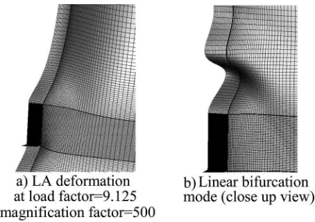
The prebuckling shape just before and the postbuckling de-formed shape just after the peak load are shown in Fig. 6. The prebuckling deformations extend far above the bracket and the postbuckling deformed shape naturally includes these deforma-tions. The incremental change between these two forms was therefore evaluated to extract the nonlinear incremental buckling mode关Fig. 6共c兲兴. The shape and location of the elastic nonlinear buckle is significantly different from the linear bifurcation mode 关Fig. 4共b兲兴. The prebuckling deformed shape关Fig. 6共a兲兴shows an enlarged flattened zone above the bracket, which leads to lower curvature and is principally responsible for the reduction in buck-ling strength.
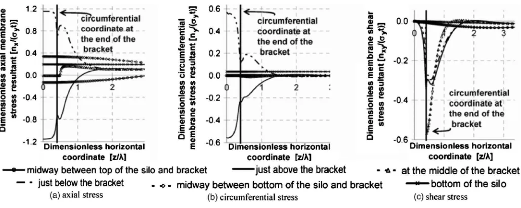
The elastic geometrically nonlinear load-deflection curve is shown in Fig. 7 共dotted兲, where the nonlinear bifurcation event can be seen to cause a sudden decrease in load, as is typical in compressed shells. The membrane stress patterns seen in this analysis are shown in Fig. 8. Three different points on the load deflection curve have been taken: one well before buckling in the elastic range, one just after buckling, and one at the lowest load on the postbuckling path. The axial membrane stress resultant 关Fig. 8共a兲兴shows that the compressive peak near the corner of the bracket is increased after buckling, as might be expected since the buckle softens the zone above the middle of the bracket. In this middle zone, the compression is highest just after buckling, but it decreases rapidly near the postbuckling minimum and moves to be tensile deep in the postbuckling range.
The circumferential membrane stress resultant above the bracket关Fig. 8共b兲兴 is dominated by a high tension developing at the bracket corner, exacerbating the high local axial compression in this location and causing early yield. These stresses are tained after buckling, making this high stress concentration sus-ceptible to yield despite the changes in geometry elsewhere caused by buckling. The membrane shear stresses at the mid-height of the bracket 关Fig. 8共c兲兴 and the circumferential mem-brane stresses below it关Fig. 8共d兲兴are substantially unchanged by
the buckling event. However, deep in the postbuckling regime, high circumferential tensile stresses develop over the bracket top.
Materially Nonlinear Analysis
When ideal elastic-plastic material nonlinearity is introduced, but small displacement theory is still adopted 共no change in geom-etry兲, the calculation leads to the reference MNA plastic collapse load 共RMNA/RREF= 0.257兲. The form of the load-deflection curve is classic关Fig. 7共black squares兲兴, with significant plastic defor-mations developing at loads well below the collapse load, but with a horizontal plateau at the collapse load. The collapse load corresponds very well to a simple theoretical calculation of full plasticity around the bracket RRef= 2 · 2d·t· 2/
冑
3 ·y+ 2 ·h·t·y/
冑
3 共Fig. 9兲, fully exploiting the biaxial stress stateprovided by the restraint of the bracket. This bracket geometry was specially selected to be in the range where strong interactions are expected between plasticity and stability, so the MNA plastic collapse load is similar to the elastic nonlinear buckling load共Fig. 7兲. The membrane stress patterns in the plastic collapse mecha-nism and at different heights in the silo are shown in Fig. 10. The axial membrane stress resultant关Fig. 10共a兲兴reaches the limits of the von Mises envelope ⫾共2/
冑
3兲Y⬇⫾1.155Y 关Fig. 9共a兲兴, above and below the bracket, but away from the bracket it de-creases to the applied load per unit circumference. The circum-ferential membrane stress resultant 关Fig. 10共b兲兴 immediately above and below the bracket reaches the corresponding reaction stress⫾Y/冑
3⬇⫾0.577Y, again consistent with this point on
von Mises ellipse, but away from the bracket it decreases to zero. Fig. 6.Deformation just before and just after buckling in geometrically nonlinear elastic analysis and resulting incremental buckling mode
Under fully plastic conditions, the stresses above and below the bracket are symmetrical共Fig. 10兲, though under elastic conditions the axial tension below the bracket was, of course, dominant.
Geometrically and Materially Nonlinear Analysis
„GMNA…
When both geometrical and material nonlinearities are included 共GMNA兲, the limit load or bifurcation seen in the geometrically nonlinear elastic analysis is, perhaps naturally, removed共Fig. 7兲 and the shell moves smoothly from an unsymmetrical prebuckling deformation pattern into a different unsymmetrical postbuckling form, passing through a limit load 共RGMNA/RREF= 0.219兲 as it does so. For this geometry, this limit load is slightly below the plastic collapse 共MNA兲and nonlinear elastic bifurcation共GNA兲 loads.
The patterns of von Mises equivalent stress on the outer sur-face of the silo are shown in Fig. 11. In the elastic range 关Fig. 11共a兲兴, the maximum surface equivalent stress lies beneath the corner of the bracket. Just before buckling关Fig. 11共b兲兴yield has occurred around most of the bracket, and just after buckling关Fig. Fig. 8.Dimensionless membrane stress resultants at different loading stages共GNA兲
Fig. 9. Simple membrane stress calculation of plastic collapse strength
11共c兲兴 the local inward directed buckle above the bracket has caused an extension of the yield zone. At the lowest load on the postbuckling path 关Fig. 11共d兲兴, this deepening local buckle be-comes extensively yielded. The images in Fig. 11 were taken from the ABAQUS共HKS 2003兲postprocessor.
The distributions of the membrane stress resultants in the geo-metrically and materially nonlinear analysis are shown in Fig. 12 on three horizontal lines adjacent to the bracket. The stress states at three different points on the load deflection path 共Fig. 7兲are shown: one in the elastic range, one just after bucking, and one far into the postbuckling range. The sharp stress concentration in axial membrane stress seen in the elastic range at the bracket corner关Fig. 8共a兲兴is rapidly smoothed by yielding after buckling 关Fig. 12共a兲兴 and a rather uniform stress transfer develops at the peak attainable stress of共2/
冑
3兲Y⬇1.155Yand this is sustaineddeep into the postbuckling range. The axial membrane stress re-sultant above the bracket shows a different behavior: the elastic peak compression that developed at the corner关Fig. 5共a兲兴moves inwards to be over the bracket after buckling, but is accompanied by a big drop in compression just beyond the corner. This drop is exacerbated in the postbuckling range. However because these stresses are strongly affected by the presence of the buckle, the uniform stress state seen in an MNA analysis关Fig. 10共a兲兴does not develop. The circumferential membrane stress resultant 关Fig. 12共c兲兴sustains the same peak at the corner throughout, but in the postbuckling range it falls to zero above the bracket. These dif-ferences between geometrically nonlinear and materially nonlin-ear stress patterns illustrate the strong interactions between changes of geometry and stress smoothing due to plasticity.
The dimensionless membrane shear resultant on a horizontal line through the middle of the bracket 关Fig. 12共d兲兴 sustains the same form from prebuckling, through buckling, and into the post-buckling range, only limited by the von Mises limit in shear Y/
冑
3⬇0.577Y and is unaffected by the buckle above thebracket. There is no suggestion of a plastic shear buckle here, even after extensive deformation, chiefly because the shear stress drops very quickly away from the bracket and there is not a large enough highly stressed zone for a buckle to develop. This is a common phenomenon in zones where shear stresses are locally high. It may be noted that a point-by-point assessment of the buckling strength, as prescribed in design standards 共 DASt-Richtlinie 1980; CEN 2006兲, is therefore very conservative if it depends on a high shear component.
In conclusion, the cylinder yields in shear on the side of the bracket just after buckling and in tension in the postbuckling range just below the bracket.
Geometrically and Materially Nonlinear with Explicit Imperfections Analysis
Many, but not all, shell buckling configurations show consider-able sensitivity to geometric imperfections. It is therefore most important to establish how imperfection sensitive the bracket-supported cylinder might be. The effect of a geometric imperfec-tion was explored using a materially and geometrically nonlinear analysis with imperfections explicitly defined共GMNIA兲, and in-troducing a linear eigenmode imperfection 关Fig. 4共b兲兴, as pro-Fig. 11. von Mises stress distribution on outer surface 共GMNA
analysis: deformation factor 15兲
posed in EN1993-1-6共CEN 2006兲, with an amplitude of one wall thickness. The resulting load deflection curve is shown in Fig. 7 共circles兲, and indicates that the imperfection simply rounds off the peak seen in the GMNA analysis, producing a slight further strength reduction共RGMNIA/RREF= 0.204兲, together with a slightly falling postfailure curve. For a cylinder under uniform compres-sion, an imperfection of this amplitude might have reduced the strength by 70% 共Rotter 2004兲. This example indicates a weak imperfection sensitivity for the bracket-supported cylinder. Fur-ther studies of imperfection sensitivity, reaching the same conclu-sion, have been undertaken共Doerich 2007兲.
Interaction between Plasticity and Buckling
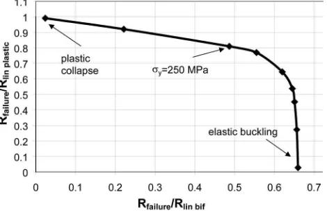
Although the example problem gives a good insight into the de-tails of the behavior of this structural arrangement, it does not illustrate what changes occur as the slenderness of the system is altered, so that either buckling or plasticity might dominate. The range of possible behaviors is most easily illustrated by studying a range of geometries or material strengths that give rise to dif-ferent slendernesses, using the plot proposed by Rotter共2003兲to capture the full range. Here, the same shape of bracket was used, but the yield stress was modified to produce different slender-nesses. This plot is shown in Fig. 13, where the ratio of the failure load of geometrically and materially nonlinear analyses to the failure load of a materially nonlinear analysis共Rfailure/Rlin plastic兲is plotted against the ratio of the failure load of a geometrically and materially nonlinear analyses to the failure load of a linear bifur-cation analysis 共Rfailure/Rlin bif兲. High slenderness configurations are found at the bottom right, where elastic buckling at a knock-down factor of 0.67 may be seen. When the slenderness has fallen so far that Rfailure/Rlin plastic reaches 0.4, the failure begins to be noticeably affected by yielding 共though local yielding has oc-curred in more slender cases兲, and plasticity begins to dominate as the stocky conditions produce failures at which the failure load of a geometrically and materially nonlinear analysis approaches the failure load of the materially nonlinear analysis共top left兲. For this problem, it is clear that geometric nonlinearity plays a strong role in slender structures and that elastic-plastic buckling affects a wide range of stockier geometries. The plastic collapse load is only approached for very stocky conditions. The example prob-lem described above was chosen, with a yield stress used ofY
= 250 MPa, to lie in the area where yielding and buckling phe-nomena would strongly interact.
Conclusions
This paper has presented an outline description of the behavior of a cylindrical steel shell that is discretely supported on several brackets, each of which is rigidly connected to a stiff column. The linear, materially nonlinear, geometrically nonlinear, and bifurca-tion behaviors of the shell have been outlined with detailed ex-planations of the changes in stress distribution arising from different geometrical and yield phenomena. The example shell geometry was chosen to illustrate interactions between bifurcation and plasticity in determining the failure condition. It has been shown that the behavior is not very imperfection sensitive, at least for this geometry, so design rules should not follow the corre-sponding formulations for uniform axial compression too closely. The different failure behaviors of a shell of the same geometry under different analyses have been explored. In the materially nonlinear analysis, plastic collapse was achieved with membrane yield all around the bracket. By contrast, GMNA showed yielding below and beside the bracket, but compressive stresses above the bracket causing buckling. The high shear stresses on the side of the bracket did not produce buckling despite attaining the yield stress, due to their rapid decay horizontally.
This bracket problem illustrates many challenges in the inter-pretation of simpler computer analyses that may be used in the practical design of shells 共CEN 2006兲. It is difficult to find a useful method of estimating of the plastic collapse strength when only linear analysis is used; the imperfection sensitivity of a sys-tem is not easily estimated on the basis of the principal stress direction causing buckling; and buckling is not easily predicted by taking the stress conditions at any single point in the structure as representing a buckling failure stress state.
References
Bijlaard, P. P.共1955兲. “Stresses from local loading in cylindrical pressure vessels.”Trans. ASME, 77, 805–816.
Cai, M., Holst, J. M. F. G., and Rotter, J. M.共2002兲. “Buckling strength of thin cylindrical shells under localized axial compression.” Proc., 15th Engineering Mechanics Conf., ASCE, Reston, Va.
DASt-Richtlinie. 共1980兲 “Beulsicherheitsnachweise für Schalen.” DASt Richtlinie 013, Deutscher Ausschuss für Stahlbau, Köln, Germany. Doerich, C. 共2007兲. “Strength and stability of locally supported
cylin-ders.” Ph.D. thesis, Univ. of Edinburgh, Edinburgh, U.K.
European Committee for Standardization共CEN兲. 共2006兲. “Eurocode 3: Design of steel structures, Part 1.6: Strength and stability of shell structures.”EN1993-1-6, Brussels, Belgium.
Flügge, W.共1973兲.Stresses in shells, 2nd Ed., Springer, Berlin. Gillie, M., Holst, J. M. F. G., Münch, M., and Rotter, J. M. 共2002兲.
“Behavior of silos supported on discrete brackets.”Int. J. Struct. Stab. Dyn., 2共1兲, 45–62.
Gould, P. L., Lowrey, R. D., Suryoutomo, H., Wang, R. S. C., and Sen, S. K. 共1976兲. “Column supported cylindrical-conical tanks.”J. Struct. Div., 102共2兲, 429–447.
Greiner, R., and Guggenberger, W.共1998兲. “Buckling behavior of axially loaded steel cylinders on local supports—With and without internal pressure.”Thin-Walled Struct., 31, 159–167.
Guggenberger, W. 共1991兲. “Buckling of cylindrical shells under local axial loads.”Proc., Int. Colloquium on Buckling of Shell Structures on Land, in the Sea and in the Air, Villeurbanne, Lyon, France, 323–333. Guggenberger, W. 共1998兲. “Proposal for design rules of axially loaded steel cylinders on local supports.”Thin-Walled Struct., 31共1–3兲, 169– 185.
Steel Res., 56共2兲, 175–197.
Hibbit, Karlsson & Sorensen Inc. 共HKS兲. 共2003兲. ABAQUS user’s manual, version 6.4, Pawntucket, R.I.
Holst, J. M. F. G., and Rotter, J. M.共2004兲. “Settlement beneath cylin-drical shells.” Buckling of thin metal shells, J. G. Teng and J. M. Rotter, eds., Spon, London, 129–153.
Holst, J. M. F. G., Rotter, J. M., Gillie, M., and Münch, M. 共2002兲. Failure criteria for shells on local supports.”New approaches to struc-tural mechanics, shells and biological structures, H.R. Drew and S. Pellegrino, eds., Kluwer Academic, London, 315–327.
Kildegaard, A.共1969兲. “Bending of a cylindrical shell subjected to axial loading.”Proc., 2nd Symp. on Theory of Thin Shells, IUTAM, Copen-hagen, Springer, Berlin, 301–315.
Li, H. Y., and Rotter, J. M.共1996兲. “Algebraic analysis of elastic circular cylindrical shells under local loadings共Part 1 and Part 2兲.”Int. Conf. on Advances in Steel Structures (ICASS ’96), Hong Kong, 801–814 and 808814, Elsevier Ltd., Oxford, U.K.
Massonnet, C. E., and Save, M. 共1972兲. Plastic analysis and design of plates, shells and disks, North-Holland Publishing Co., Amsterdam, The Netherlands.
Nemeth, M. P., and Starnes, J. H.共1998兲.The NASA monographs on shell stability design recommendations—A review and suggested improve-ments, NASA TP 1998-206290, Langley Research Center, Hampton, Va.
Peter, J.共1974兲. “Zur stabilitat von Kreiscylinderschalen unter ungleich-maessig verteilten axialen randbelastungen.” Ph.D. thesis, Univ. of Hannover, Hannover, Germany.
Reissner, E.共1940兲. “Note on the problem of the distribution of stress in
a thin stiffened elastic sheet.”Proc. Natl. Acad. Sci. U.S.A., 26, 300– 305.
Rotter, J. M.共1998兲. “Shell structures: The new European standard and current research needs.”Thin-Walled Struct., 31共1–3兲, 3–23. Rotter, J. M.共2003兲. “Buckling of shallow conical shell roofs for small
diameter tanks and silos.”Int. Conf. on Design, Inspection, and Main-tenance of Cylindrical Steel Tanks and Pipelines, Prague, Czech Re-public, 169–175.
Rotter, J. M.共2004兲. “Buckling of cylindrical shells under axial compres-sion.”Buckling of thin metal shells, J. G. Teng and J. M. Rotter, eds., Spon, London, 42–87.
Rotter, J. M., Teng, J. G., and Li, H. Y.共1991兲. “Buckling in thin elastic cylinders on column supports.”Proc., Int. Colloquium on Buckling of Shell Structures on Land, in the Sea and in the Air, Villeurbanne, Lyon, France, 334–343.
Teng, J. G., and Rotter, J. M.共1990兲. “A study of buckling in column-supported cylinders.”Contact loading and local effects in thin-walled plated and shell structures, V. Krupka and M. Drdacky, eds., Aca-demia Press, Prague, Czechoslovakia, 52–61.
Teng, J. G., and Rotter, J. M. 共1992兲. “Linear bifurcation of perfect column-supported cylinders—Support modeling and boundary condi-tions.”Thin-Walled Struct., 14共3兲, 241–263.
Timoshenko, S. P., and Goodier, J. N.共1970兲.Theory of elasticity, 3rd Ed., McGraw-Hill, New York.
Wang, R. S. C., and Gould, P. L. 共1974兲. “Continuously supported cylindrical-conical tanks.”J. Struct. Div., 100共10兲, 2037–2052. Yamaki, N.共1984兲.Elastic stability of circular cylindrical shells, Elsevier