THE
RAILMAPPER
-A DEDIC-ATED MOBILE LID-AR M-APPING SYSTEM FOR R-AILW-AY NETWORKS
Jens Kremer & Albrecht Grimm
IGI mbH, Langenauer Straße 46, 57223 Kreuztal, Germany – (j.kremer, a.grimm)@igi-systems.com
ICWG V/I: Land-Based Mobile Mapping Systems
KEY WORDS: Mobile Mapping, GPS/INS, LiDAR, Multisensor Systems
ABSTRACT:
The Mobile LiDAR Mapping System StreetMapper from IGI and 3D Laser Mapping (Bingham Nottingham, UK) is mounted on a large variety of road vehicles to cover different mission specifications. In addition to the operation on the road, the system finds its applications on other kinds of vehicles, like boats or trains. The modular and flexible system concept even allows utilizing the same LiDAR Mapping system for Mobile Mapping on the ground and for airborne missions on helicopters, respectively.
Besides this general flexibility, each application has its own special requirements. Special hardware and software components are needed to complete the core components, like the laser scanner and the GNSS/IMU systems, to build a dedicated system for the chosen task.
Compared to the typical dynamics of a road vehicle mounted Mobile Mapping system, a dedicated rail mapping system operates under conditions that are much more challenging for a high accuracy GNSS/IMU trajectory determination. Furthermore, the typical rail mapping tasks, like the exact measurement of the rail track geometry, require the operation of the most accurate laser scanners and of specialized post-processing software.
In this paper, the RailMapper, a specialized Mobile Mapping system for railway surveys is presented. The system is described with focus on the railway specific requirements and results of practical surveys are given.
1. INTRODUCTION
Airborne LiDAR is a well proven and widely used technology for providing digital surface models of large areas and long objects, as well as precise geometrical information of infrastructure facilities like power lines. For these applications the airborne operation brings the advantage of the high productivity of airborne missions and the good visibility from the high viewpoint. On the other hand the relatively high cost of aerial operations and the special airborne perspective are limiting the use of this method. Therefore the operation of Mobile LiDAR Mapping systems on other platforms such as cars, boats or trains has become increasingly important over the last years.
Common to all high accuracy Mobile LiDAR Mapping systems are the following core components: successfully under all the different conditions. In practice the components are often optimized for the special conditions of a number of similar applications. For example the range of an airborne scanner has to be much higher than the range of a car based Mobile Mapper. Nevertheless, for applications with similar requirements it makes sense to design the systems in a way that enables the operation from different platforms.
The Mobile LiDAR Mapping system StreetMapper from IGI and 3DLM is mounted on a large variety of road vehicles to
cover different mission specifications. In addition to the operation on the road, the system finds its applications on other kinds of vehicles, like boats or trains. The modular and flexible system concept even allows utilizing the same LiDAR Mapping system for Mobile Mapping on the ground and for airborne missions on helicopters.
Besides the different requirements in range and accuracy, the operation on different platforms implies different challenges for the precise GNSS/IMU navigation. Error sources like multi path effects or obstructions are generally much stronger for the ground based operation. In addition to the more difficult navigation, the accuracy requirements are mostly very strict in this case.
In this paper the RailMapper, a specialized Mobile Mapping system for railway surveys is described. The use of Mobile LiDAR Mapping for railways is of great interest. On one hand a heavily used rail network has a large demand of continuous monitoring, but on the other hand it is costly to assure the rails for safe conventional surveying and monitoring work. High accuracy Mobile LiDAR Mapping systems can collect data during normal railway operation.
From the technical point of view the exact measurement of rail geometry and the direct vicinity of the rails is a difficult task: The demand of an extremely high accuracy has to be fulfilled under the difficult GNSS conditions that are caused by the many buildings and the vegetation that often go along with the rail trails.
2. THE RAILMAPPER SYSTEM
The basis of the development of a dedicated mobile LiDAR mapping system for rail networks at IGI is the StreetMapper system (e.g. G. Hunter 2009, N. Haala et. al. 2008). Although this Mobile Mapping System was initially developed for the use
on cars, the users of the system have successfully mounted the system to other platforms like boats, trams or even low flying helicopters.
Figure 1: StreetMapper Mobile Mapping Vehicle
Figure 2: Scanner, camera and IMU of a StreetMapper mounted on a boat and in a helicopter pod
Figure 3: StreetMapper operated on a hi-rail gear vehicle (Photo: Terrametrix LLC, Omaha, NE, USA)
This operation on different platforms is supported by the modular design of the system.
While this multi-platform operation was appropriate for projects on trams and small to medium sized projects, a dedicated rail mapping system appears to be useful for the daily surveying and monitoring work on large rail networks. Depending on the intended operational conditions, the dedicated rail mapping system is installed on a measurement train or on a road-rail vehicle.
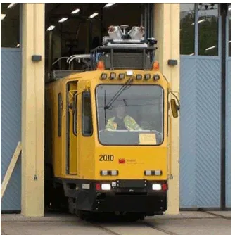
Figure 4: StreetMapper sensor assembly mounted on a tram in Helsinki
2.1 Navigation System
IGIs TERRAcontrol GNSS/IMU system provides the precise position and orientation for georeferencing of the LiDAR pointcloud as well as of the digital images. The TERRAcontrol SMU (Sensor Management Unit) can collect feedback signals of multiple sensors. For that reason, not only the installed optical digital cameras, but also optional additional equipment like the thermal camera DigiTHERM (Kremer 2011) or a corona camera can be time-tagged and georeferenced.
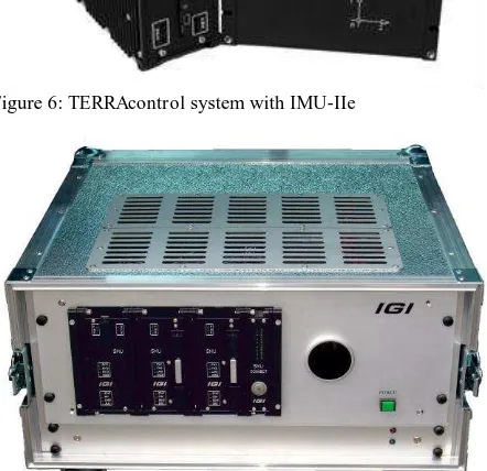
For the RailMapper systems the TERRAcontrol IMU-IIe with 400 Hz data rate is operated. The TERRAcontrol is equipped with the DIA+ option. This means that the INS real time navigation information is used by the GNSS receiver to improve the GNSS data collection after the loss of satellite lock in situation like the passage of a tunnel (cf. Hunter 2009). In addition to the GPS signals, the GLONASS information is exploited. Especially for missions with low number of GPS satellites this additional information is very helpful. Figure 5 documents that for a part of a RailMapper mission in Sweden. The upper view shows the number of used GPS satellites only. In the second diagram the number of used satellites for a combined GPS/GLONASS processing is given.
Figure 5: Comparison of the number of satellites in view. GPS only and GPS + GLONASS
To reduce the error growth in case of long sections with no GNSS, the system is equipped with a speed sensor.
For installation in rough environments the IMU can be fit into a rugged and water tight housing.
The control rack for the StreetMapper and the RailMapper is built based on SMUs (Sensor Management Units) that were developed for IGIs aerial sensor systems. The SMUs together with the additional mission specific components, like power
supplies or converters for special interfaces, are combined in rugged racks (Figure 7).
Figure 6: TERRAcontrol system with IMU-IIe
Figure 7: RailMapper control rack
2.2 Laser Scanner
The RailMapper can be equipped with different laser scanners. The standard scanners are of the type Riegl VQ-450.
Scanners of other type, e.g. the FARO FOCUS 3D, are actually under test at IGI for this application.
2.3 Sensor Assembly
In contrast to the design of an airborne laser scanning system, the minimisation of the weight of the sensor assembly does not play a significant role for a rail mapping system. Nevertheless, a relatively low weight and a convenient handling reduces the setup-time and therefore it improves the flexibility in case of changes of the surveying vehicle or modifications in the sensor configuration.
The sensor assembly of the RailMapper consists of a rigid aluminium profile that holds the sensor components, the IMU and a pole with the GNSS antenna. The profile is connected to the vehicle with shock mounts. The electronic rack with the data storage and the user interface is placed inside the vehicle.
Figure 8: RailMapper sensor assembly with three laser scanners operated on a “Diagnose VT” of the Deutsche Bahn AG
2.4 Software for Georeferencing and Data Adjustment
Even though some information about the quality and integrity of the data is displayed for the sensor operator in real time, the high accuracy processing of the navigation data and the LiDAR data is generally done in an offline process. In a first step, the trajectory and the orientation of the sensor assembly is calculated from the TERRAcontrol navigation system data. This calculation is done with the TERRAoffice option of the software package IGI AEROoffice. In a second step the LiDAR range measurements are georeferenced with the trajectory data with the software SM Process (3D Laser Mapping).
The system is pre-calibrated. This means that the relative orientation of the sensors and the IMU had been determined before the installation on the train. The pre-calibration eliminates the need to drive special calibration patterns, because this is hardly possible on a rail-bound vehicle.
Depending on the mission conditions and on the accuracy requirements, the georeferenced LiDAR data can be adjusted and ground control points can be introduced using the TerraMatch software from Terrasolid Ltd., Finland.
2.5 Data Post Processing Software
The result of the data pre-processing are georeferenced point clouds and oriented digital images. These intermediate results can be introduced into various software packages, depending on the application. Possible options are e.g. CARD/1 from IB&T GmbH, Germany, the software products from Terrasolid Ltd, Finland, or the software package SiRailScan from technet-rail GmbH, Germany.
3. DATA EXAMPLES
Even though the focus of the Mobile LiDAR Missons on railroads is on the rail specific applications, the RailMapper data allows for the full spectrum of common LiDAR Mobile Mapping applications. Therefore the following examples show only a selection of the possible applications.
3.1 Clearance and Rail Parameter Measurements
The collection, evaluation and management of the clearance over the rail track is an important prerequisite for the save operation of the rail network, especially for the save transport of goods with oversize or overweight. Therefore the network operator has to capture the clearance profile and to collect possible clearance profile narrow points. However, not only the narrow points and the position and shape of the obstacles, but also other parameters like the gauge of the track, the super-elevation, the gradient and the radius have to be known.
For the clearance measurement for Deutsche Bahn AG, every object that reaches into a profile as given in Figure 9 has to be measured.
Figure 9: Definition of the space for the documentation of clearance narrow points (cf. Deutsche Bahn AG guidelines “Ril 458 458.0108”)
Within this profile, smaller profiles have to be checked for possible clearance violations. Within these profiles, no object must be located.
Figure 10: Standard clearance profile “G2”
For the detection of the clearance narrow points from the RailMapper data, the profile of standard rails has to be fit to the LiDAR point cloud. This fit defines the track axis and the track parameters like gauge, super-elevation, gradient and radius.
Figure 11: Determination of the super elevation of the used track and of neighbouring track
Along this track axis the test profile can be moved though the points to detect the clearance violations. This task can be fulfilled with software packages like SiRailScan or TerraScan mentioned above.
Figure 12: Checking the clearance inside a tunnel with TerraScan
Figure 13: Automatic check of the clearance with SiRailScan
For the Deutsche Bahn AG, the results of the clearance measurements have to be documented in a specific format (“LUE”). In addition to the clearance measurements, supplemental information like camera images or point cloud screenshots can be saved with the data. This extended dataset (“LIE”) can be imported into the clearance database and evaluated with the software WinLUE. In Figure 14 and Figure 15 an example of a clearance narrow point detected with RailMapper near Weilburg/Lahn in Germany can be seen.
Figure 14: Evaluation of a clearance narrow point with WinLUE. Left: “LUE” information. Middle: “G2” profile and the sign that violates the clearance. Right: Screenshot of the point cloud
Figure 15: Camera image that is linked to the position documented in Figure 14
3.2 Measurement of the Catenary Wire
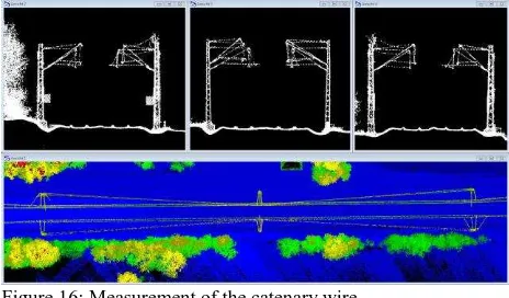
The high density and the point cloud and the operation principle of the deployed laser scanner allows for an exact measurement of the height and the position of the catenary wire and of the wire support.
Figure 16: Measurement of the catenary wire
3.3 Documentation of Railroad Crossings
The documentation of railroad crossings is another possible application for the RailMapper data.
Figure 18 shows the documentation of a railroad crossing with the program Master from the company technet-rail. BÜ-Master is a software that was especially designed for the demands of Deutsche Bahn AG for infrastructure documentation of railroad crossings. The created plans of train stations and railroad lines can be imported and the measurement data can be exported to the DB-GIS database of Deutsche Bahn AG.
Figure 17: Point cloud of a railroad crossing
Figure 18: Documentation of the crossing shown in Figure 17 created with BÜ-Master
3.4 Tree-fall Simulations
Another application for the RailMapper data is the simulation of tree fall situations around the rail track. Figure 19 and 20 show the parts of the vegetation in the direct vicinity of the rail track that could cause a thread for traffic and facilities on the rail track. The algorithm takes the position of the rail, the position of the vegetation and the local ground level into account. These simulations were conducted by the company Nebel & Partner with RailMapper data from survey project conducted in Sweden in 2011.
Figure 19: Checking the tree-fall hazard around a rail track in Sweden using TerraScan (profile)
Figure 20: Checking the tree-fall hazard around a rail track in Sweden using TerraScan (top view)
3.5 Coloured Point Clouds
In the RailMapper, LiDAR is combined with directly georeferenced digital cameras. The camera images can be utilized to texture surface models that are extracted from the point cloud, or they can be used to assign a colour to the measured LiDAR points (Figure 21).
Figure 21: Coloured point cloud of a small train station
3.6 Local DTMs
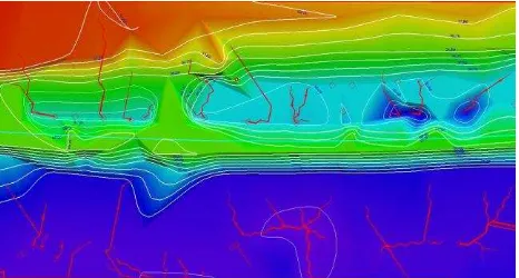
The LiDAR point cloud is used to create very exact and dense Digital Terrain Models of the vicinity of the railtrack. The results of the Mobile Mapping Vehicle can be combined with data from Airborne LiDAR to create DTMs that are densified around the rail track and that provide a full coverage in areas that show occlusions in the aerial data. Figure 22 shows the application of a local high density DTM for the simulation of water drainage with the software TerraModeller.
Figure 22: Drainage simulation based on RailMapper data using TerraModeller
4. CONCLUSION
The RailMapper is a specialized Mobile Mapping system for railway surveys. It uses state of the art laser scanners and GNSS/IMU navigation. The data produced by the system is compatible to numerous available software packages to cover a wide range of rail specific and general surveying and monitoring tasks.
5. ACKNOWLEDGMENTS
The authors would like to thank Mr. Robert Hau from Nebel & Partner, Schleswig, Germany for providing information and figures about the given examples.
6. REFERENCES
HAALA, N., Peter, M., Kremer, J. & Hunter, G. (2008): Mobile LiDAR Mapping for 3D Point Cloud Collection in Urban Areas - a Performance Test. The International Archives of the Photogrammetry, Remote Sensing and Spatial Information Sciences, Vol. XXXVII, Part B5, Commission 5. ISPRS Congress 2008, Beijing, China. P. 1119ff. ISSN 1682-1750.
HUNTER, G. (2009): Mobile Mapping – The StreetMapper Approach. Photogrammetric Week 09 (Ed. D. Fritsch), Wichmann, Berlin/Offenbach, pp. 179-190.
KREMER, J. (2011): Power Line Mapping - Data Acquisition with a Specialized Multi-Sensor Platform. Photogrammetric Week 11 (Ed. D. Fritsch), Wichmann, Berlin/Offenbach, pp. 147-154.