Getting
Started
with
Arduino
Massimo Banzi
Getting Started with Arduino
by Massimo Banzi
Copyright © 2011 Massimo Banzi. All rights reserved. Printed in the U.S.A.
Published by Make:Books, an imprint of Maker Media, a division of O’Reilly Media, Inc.
1005 Gravenstein Highway North, Sebastopol, CA 95472 O’Reilly books may be purchased for educational, business, or sales promotional use. For more information, contact our corporate/institutional sales department: 800-998-9938
Illustrations: Elisa Canducci with Shawn Wallace
The O’Reilly logo is a registered trademark of O’Reilly Media, Inc. The Make: Projects series designations and related trade dress are trademarks of O’Reilly Media, Inc. The trademarks of third parties used in this work are the property of their respective owners.
Important Message to Our Readers: Your safety is your own responsibility, including proper use of equipment and safety gear, and determining whether you have adequate skill and experi-ence. Electricity and other resources used for these projects are dangerous unless used properly and with adequate precautions, including safety gear. Some illustrations do not depict safety precautions or equipment, in order to show the project steps more clearly. These projects are not intended for use by children. Use of the instructions and suggestions in Getting Started with Arduino is at your own risk. O’Reilly Media, Inc., and the author disclaim all responsibility for any resulting damage, injury, or expense. It is your responsibility to make sure that your activities comply with applicable laws, including copyright.
Use a Light Sensor Instead of the Pushbutton . . . .60
Analogue Input . . . .62
Try Other Analogue Sensors . . . .66
Serial Communication . . . .66
Driving Bigger Loads (Motors, Lamps, and the Like) . . . .68
Complex Sensors . . . .68
6/Talking to the Cloud . . . 7 1 Planning . . . .73
Coding . . . .74
Assembling the Circuit . . . .81
Here’s How to Assemble It . . . .82
7/Troubleshooting . . . 85
Testing the Board . . . .86
Testing Your Breadboarded Circuit . . . .87
Isolating Problems . . . .88
Problems with the IDE . . . .88
How to Get Help Online . . . .89
Appendices . . . 91
Appendix A/The Breadboard . . . .91
Appendix B/Reading Resistors and Capacitors . . . .93
Appendix C/Arduino Quick Reference . . . .9 5 Appendix D/Reading Schematic Diagrams . . . .108
Preface
A few years ago I was given a very interesting
challenge: teach designers the bare minimum
in electronics so that they could build
inter-active prototypes of the objects they were
designing.
I started following a subconscious instinct to teach electronics the same way I was taught in school. Later on I realised that it simply wasn’t working as well as I would like, and started to remember sitting in a class, bored like hell, listening to all that theory being thrown at me without any practical application for it.
In reality, when I was in school I already knew electronics in a very empirical way: very little theory, but a lot of hands-on experience.
I started thinking about the process by which I really learned electronics:
» I took apart any electronic device I could put my hands on.
» I slowly learned what all those components were.
» I began to tinker with them, changing some of the connections inside
of them and seeing what happened to the device: usually something between an explosion and a puff of smoke.» I started building some kits sold by electronics magazines.
projects at the time were a dishwasher and an early computer that came from an insurance ofice, which had a huge printer, electronics cards, magnetic card readers, and many other parts that proved very interesting and challenging to completely take apart.
After quite a lot of this dissecting, I knew what electronic components were and roughly what they did. On top of that, my house was full of old electronics magazines that my father must have bought at the beginning of the 1970s. I spent hours reading the articles and looking at the circuit diagrams without understanding very much.
This process of reading the articles over and over, with the beneit of knowledge acquired while taking apart circuits, created a slow virtuous circle.
A great breakthrough came one Christmas, when my dad gave me a kit that allowed teenagers to learn about electronics. Every component was housed in a plastic cube that would magnetically snap together with other cubes, establishing a connection; the electronic symbol was written on top. Little did I know that the toy was also a landmark of German design, because Dieter Rams designed it back in the 1960s.
With this new tool, I could quickly put together circuits and try them out to see what happened. The prototyping cycle was getting shorter and shorter.
After that, I built radios, ampliiers, circuits that would produce horrible noises and nice sounds, rain sensors, and tiny robots.
I’ve spent a long time looking for an English word that would sum up that way of working without a speciic plan, starting with one idea and ending up with a completely unexpected result. Finally, “tinkering” came along. I recognised how this word has been used in many other ields to describe a way of operating and to portray people who set out on a path of explora-tion. For example, the generation of French directors who gave birth to the “Nouvelle Vague” were called the “tinkerers”. The best deinition of tinkering that I’ve ever found comes from an exhibition held at the Exploratorium in San Francisco:
Contraptions, machines, wildly mismatched objects working in harmony— this is the stuf of tinkering.
Tinkering is, at its most basic, a process that marries play and inquiry.
—www.exploratorium.edu/tinkering
From my early experiments I knew how much experience you would need in order to be able to create a circuit that would do what you wanted start-ing from the basic components.
Another breakthrough came in the summer of 1982, when I went to London with my parents and spent many hours visiting the Science Museum. They had just opened a new wing dedicated to computers, and by follow-ing a series of guided experiments, I learned the basics of binary math and programming.
There I realised that in many applications, engineers were no longer build-ing circuits from basic components, but were instead implementbuild-ing a lot of the intelligence in their products using microprocessors. Software was replacing many hours of electronic design, and would allow a shorter tinkering cycle.
When I came back I started to save money, because I wanted to buy a computer and learn how to program.
My irst and most important project after that was using my brand-new ZX81 computer to control a welding machine. I know it doesn’t sound like a very exciting project, but there was a need for it and it was a great chal-lenge for me, because I had just learned how to program. At this point, it became clear that writing lines of code would take less time than modify-ing complex circuits.
Acknowledgments
This book is dedicated to Luisa and Alexandra.
First of all I want to thank my partners in the Arduino Team: David Cuartielles, David Mellis, Gianluca Martino, and Tom Igoe. It is an amazing experience working with you guys.
Barbara Ghella, she doesn’t know, but, without her precious advice, Arduino and this book might have never happened.
Bill Verplank for having taught me more than Physical Computing.
Gillian Crampton-Smith for giving me a chance and for all I have learned from her.
Hernando Barragan for the work he has done on Wiring.
Brian Jepson for being a great editor and enthusiastic supporter all along.
Nancy Kotary, Brian Scott, Terry Bronson, and Patti Schiendelman for turning what I wrote into a inished book.
I want to thank a lot more people but Brian tells me I’m running out of space, so I’ll just list a small number of people I have to thank for many reasons:
How to Contact Us
We have veriied the information in this book to the best of our ability, but you may ind things that have changed (or even that we made mistakes!). As a reader of this book, you can help us to improve future editions by sending us your feedback. Please let us know about any errors, inaccuracies, misleading or confusing statements, and typos that you ind anywhere in this book.
Please also let us know what we can do to make this book more useful to you. We take your comments seriously and will try to incorporate reasonable suggestions into future editions.
You can write to us at:
Maker Media
1005 Gravenstein Highway North Sebastopol, CA 95472
(800) 998-9938 (in the U.S. or Canada) (707) 829-0515 (international/local) (707) 829-0104 (fax)
Maker Media is a division of O’Reilly Media devoted entirely to the growing community of resourceful people who believe that if you can imagine it, you can make it. Consisting of MAKE magazine, CRAFT magazine, Maker Faire, as well as the Hacks, Make:Projects, and DIY Science book series, Maker Media encourages the Do-It-Yourself mentality by providing creative inspiration and instruction.
For more information about Maker Media, visit us online: MAKE www.makezine.com
The O’Reilly web site for Getting Started with Arduino lists examples, errata, and plans for future editions. You can ind this page at www.makezine.com/getstartedarduino.
1
/
Introduction
Arduino is an open source physical computing
platform based on a simple input/output
(I/O) board and a development environment
that implements the Processing language
(
www.processing.org
). Arduino can be used
to develop standalone interactive objects
or can be connected to software on your
computer (such as Flash, Processing, VVVV,
or Max/MSP). The boards can be assembled
by hand or purchased preassembled; the
open source IDE (Integrated Development
Environment) can be downloaded for free
from
www.arduino.cc
.
Arduino is different from other platforms on the market because of these features:
» It is a multiplatform environment; it can run on Windows, Macintosh,
and Linux.» It is based on the Processing programming IDE, an easy-to-use
development environment used by artists and designers.» The hardware is cheap. The USB board costs about €20 (currently,
about US$35) and replacing a burnt-out chip on the board is easy and costs no more than €5 or US$4. So you can afford to make mistakes.» There is an active community of users, so there are plenty of people
who can help you.» The Arduino Project was developed in an educational environment and
is therefore great for newcomers to get things working quickly.This book is designed to help beginners understand what beneits they can get from learning how to use the Arduino platform and adopting its philosophy.
Intended Audience
This book was written for the “original” Arduino users: designers and artists. Therefore, it tries to explain things in a way that might drive some engineers crazy. Actually, one of them called the introductory chapters of my irst draft “luff”. That’s precisely the point. Let’s face it: most engineers aren’t able to explain what they do to another engineer, let alone a regular human being. Let’s now delve deep into the luff.
NOTE: Arduino builds upon the thesis work Hernando Barragan did on the Wiring platform while studying under Casey Reas and me at IDII Ivrea.
After Arduino started to become popular, I realised how experimenters, hobbyists, and hackers of all sorts were starting to use it to create beauti-ful and crazy objects. I realised that you’re all artists and designers in your own right, so this book is for you as well.
Arduino was born to teach Interaction Design, a design discipline that puts prototyping at the centre of its methodology. There are many deini-tions of Interaction Design, but the one that I prefer is:
Interaction Design is the design of any interactive experience.
of ever-increasing idelity. This approach—also part of some types of “conventional” design—can be extended to include prototyping with technology; in particular, prototyping with electronics.
The speciic ield of Interaction Design involved with Arduino is Physical Computing (or Physical Interaction Design).
What Is Physical Computing?
Physical Computing uses electronics to prototype new materials for designers and artists.
It involves the design of interactive objects that can communicate with humans using sensors and actuators controlled by a behaviour imple-mented as software running inside a microcontroller (a small computer on a single chip).
In the past, using electronics meant having to deal with engineers all the time, and building circuits one small component at the time; these issues kept creative people from playing around with the medium directly. Most of the tools were meant for engineers and required extensive knowledge. In recent years, microcontrollers have become cheaper and easier to use, allowing the creation of better tools.
The progress that we have made with Arduino is to bring these tools one step closer to the novice, allowing people to start building stuff after only two or three days of a workshop.
2
/
The Arduino Way
The Arduino philosophy is based on making
designs rather than talking about them. It is
a constant search for faster and more
power-ful ways to build better prototypes. We have
explored many prototyping techniques and
developed ways of thinking with our hands.
Classic engineering relies on a strict process for getting from A to B; the Arduino Way delights in the possibility of getting lost on the way and inding C instead.
This is the tinkering process that we are so fond of—playing with the medium in an open-ended way and inding the unexpected. In this search for ways to build better prototypes, we also selected a number of soft-ware packages that enable the process of constant manipulation of the software and hardware medium.
Prototyping is at the heart of the Arduino Way: we make things and build objects that interact with other objects, people, and networks. We strive to ind a simpler and faster way to prototype in the cheapest possible way.
A lot of beginners approaching electronics for the irst time think that they have to learn how to build everything from scratch. This is a waste of energy: what you want is to be able to conirm that something’s working very quickly so that you can motivate yourself to take the next step or maybe even motivate somebody else to give you a lot of cash to do it.
This is why we developed “opportunistic prototyping”: why spend time and energy building from scratch, a process that requires time and in-depth technical knowledge, when we can take ready-made devices and hack them in order to exploit the hard work done by large companies and good engineers?
Our hero is James Dyson, who made 5127 prototypes of his vacuum cleaner before he was satisied that he’d gotten it right (www.international. dyson.com/jd/1947.asp).
Tinkering
We believe that it is essential to play with technology, exploring different possibilities directly on hardware and software—sometimes without a very deined goal.
Patching
I have always been fascinated by modularity and the ability to build complex systems by connecting together simple devices. This process is very well represented by Robert Moog and his analogue synthesizers. Musicians constructed sounds, trying endless combinations by “patching together” different modules with cables. This approach made the synthesizer look like an old telephone switch, but combined with the numerous knobs, that was the perfect platform for tinkering with sound and innovating music. Moog described it as a process between “witnessing and discovering”. I’m sure most musicians at irst didn’t know what all those hundreds of knobs did, but they tried and tried, reining their own style with no inter-ruptions in the low.
Reducing the number of interruptions to the low is very important for creativity—the more seamless the process, the more tinkering happens.
Circuit Bending
Computer keyboards are still the main way to interact with a computer after more than 60 years. Alex Pentland, academic head of the MIT Media Laboratory, once remarked: “Excuse the expression, but men’s urinals are smarter than computers. Computers are isolated from what’s around them.”1
We Love Junk!
Hacking Toys
Collaboration
3
/
The Arduino Platform
Arduino is composed of two major parts: the
Arduino board, which is the piece of hardware
you work on when you build your objects; and
the Arduino IDE, the piece of software you run
on your computer. You use the IDE to create
a sketch (a little computer program) that you
upload to the Arduino board. The sketch tells
the board what to do.
Not too long ago, working on hardware meant building circuits from scratch, using hundreds of different components with strange names like resistor, capacitor, inductor, transistor, and so on.
Every circuit was “wired” to do one speciic application, and making changes required you to cut wires, solder connections, and more.
With the appearance of digital technologies and microprocessors, these functions, which were once implemented with wires, were replaced by software programs.
Software is easier to modify than hardware. With a few keypresses, you can radically change the logic of a device and try two or three versions in the same amount of time that it would take you to solder a couple of resistors.
The Arduino Hardware
micro-We (the Arduino team) have placed on this board all the components that are required for this microcontroller to work properly and to communicate with your computer. There are many versions of this board; the one we’ll use throughout this book is the Arduino Uno, which is the simplest one to use and the best one for learning on. However, these instructions apply to earlier versions of the board, including the Arduino Duemilanove from 2009. Figure 3-1 shows the Arduino Uno; Figure 3-2 shows the Arduino Duemilanove.
In those illustrations, you see the Arduino board. At irst, all those con-nectors might be a little confusing. Here is an explanation of what every element of the board does:
14 Digital IO pins (pins 0–13)
These can be inputs or outputs, which is speciied by the sketch you create in the IDE.
6 Analogue In pins (pins 0–5)
These dedicated analogue input pins take analogue values (i.e., voltage readings from a sensor) and convert them into a number between 0 and 1023.
6 Analogue Out pins (pins 3, 5, 6, 9, 10, and 11)
These are actually six of the digital pins that can be reprogrammed for analogue output using the sketch you create in the IDE.
The board can be powered from your computer’s USB port, most USB chargers, or an AC adapter (9 volts recommended, 2.1mm barrel tip, center positive). If there is no power supply plugged into the power socket, the power will come from the USB board, but as soon as you plug a power supply, the board will automatically use it.
The Software (IDE)
The IDE (Integrated Development Environment) is a special program running on your computer that allows you to write sketches for the Arduino board in a simple language modeled after the Processing (www.processing.org) language. The magic happens when you press the button that uploads the sketch to the board: the code that you have written is translated into the C language (which is generally quite hard for a beginner to use), and is passed to the avr-gcc compiler, an important piece of open source software that makes the inal translation into the language understood by the microcontroller. This last step is quite impor-tant, because it’s where Arduino makes your life simple by hiding away as much as possible of the complexities of programming microcontrollers.
The programming cycle on Arduino is basically as follows:
» Plug your board into a USB port on your computer.
» Write a sketch that will bring the board to life.
» Upload this sketch to the board through the USB connection and wait
a couple of seconds for the board to restart.» The board executes the sketch that you wrote.
NOTE: Linux installation is complicated at the time of this writing. See
www.arduino.cc/playground/Learning/Linux for instructions.
Installing Arduino on Your Computer
To program the Arduino board, you must irst download the development environment (the IDE) from here: www.arduino.cc/en/Main/Software. Choose the right version for your operating system.
NOTE: If you have any trouble running the Arduino IDE, see Chapter 7, Troubleshooting.
Now you must install the drivers that allow your computer to talk to your board through the USB port.
Installing Drivers: Macintosh
The Arduino Uno on a Mac uses the drivers provided by the operating sys-tem, so the procedure is quite simple. Plug the board into your computer.
The PWR light on the board should come on and the yellow LED labelled “L” should start blinking.
You might see a popup window telling you that a new network interface has been detected.
If that happens, Click “Network Preferences...”, and when it opens, click “Apply”. The Uno will show up as “Not Conigured”, but it’s working prop-erly. Quit System Preferences.
If you have an older Arduino board, look for instructions here:
www.arduino.cc/en/Guide/MacOSX.
If the Arduino doesn’t work, see Chapter 7, Troubleshooting.
Installing Drivers: Windows
Plug the Arduino board into the computer; when the Found New Hard-ware Wizard window comes up, Windows will irst try to ind the driver on the Windows Update site.
Windows XP will ask you whether to check Windows Update; if you don’t want to use Windows Update, select the “No, not at this time” option and click Next.
Navigate to and select the Uno’s driver ile, named ArduinoUNO.inf, located in the “Drivers” folder of the Arduino Software download (not the “FTDI USB Drivers” sub-directory). Windows will inish up the driver installation from there.
If you have an older board, look for instructions here:
www.arduino.cc/en/Guide/Windows.
Once the drivers are installed, you can launch the Arduino IDE and start using Arduino.
Port Identiication: Macintosh
From the Tools menu in the Arduino IDE, select “Serial Port” and select the port that begins with /dev/cu.usbmodem; this is the name that your computer uses to refer to the Arduino board. Figure 3-3 shows the list of ports.
Figure 3-3.
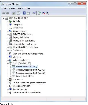
Port Identiication: Windows
On Windows, the process is a bit more complicated—at least at the begin-ning. Open the Device Manager by clicking the Start menu, right-clicking on Computer (Vista) or My Computer (XP), and choosing Properties. On Windows XP, click Hardware and choose Device Manager. On Vista, click Device Manager (it appears in the list of tasks on the left of the window).
Look for the Arduino device in the list under “Ports (COM & LPT)”. The Arduino will appear as “Arduino UNO” and will have a name like COM3, as shown in Figure 3-4.
Figure 3-4.
NOTE: On some Windows machines, the COM port has a number greater than 9; this numbering creates some problems when Arduino is trying to communicate with it. See Chapter 7, Troubleshooting, for help on this problem.
Once you’ve igured out the COM port assignment, you can select that port from the Tools > Serial Port menu in the Arduino IDE.
4
/
Really Getting Started
with Arduino
Now you’ll learn how to build and program an
interactive device.
Anatomy of an Interactive Device
All of the objects we will build using Arduino follow a very simple pattern that we call the “Interactive Device”. The Interactive Device is an electronic circuit that is able to sense the environment using sensors (electronic components that convert real-world measurements into electrical signals). The device processes the information it gets from the sensors with behaviour that’s implemented as software. The device will then be able to interact with the world using actuators, electronic components that can convert an electric signal into a physical action.
Sensors
Actuators
Behavior (software) Sense/Perceive
Sensors and Actuators
Sensors and actuators are electronic components that allow a piece of electronics to interact with the world.
As the microcontroller is a very simple computer, it can process only electric signals (a bit like the electric pulses that are sent between neurons in our brains). For it to sense light, temperature, or other physical quantities, it needs something that can convert them into electricity. In our body, for example, the eye converts light into signals that get sent to the brain using nerves. In electronics, we can use a simple device called a light-dependent resistor (an LDR or photoresistor) that can measure the amount of light that hits it and report it as a signal that can be understood by the micro-controller.
Once the sensors have been read, the device has the information needed to decide how to react. The decision-making process is handled by the microcontroller, and the reaction is performed by actuators. In our bodies, for example, muscles receive electric signals from the brain and convert them into a movement. In the electronic world, these functions could be performed by a light or an electric motor.
In the following sections, you will learn how to read sensors of different types and control different kinds of actuators.
Blinking an LED
The LED blinking sketch is the irst program that you should run to test whether your Arduino board is working and is conigured correctly. It is also usually the very irst programming exercise someone does when learn-ing to program a microcontroller. A light-emittlearn-ing diode (LED) is a small electronic component that’s a bit like a light bulb, but is more eficient and requires lower voltages to operate.
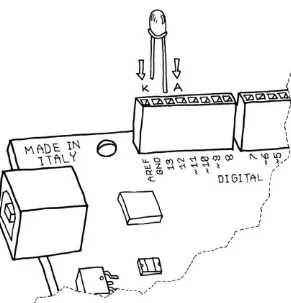
Your Arduino board comes with an LED preinstalled. It’s marked “L”. You can also add your own LED—connect it as shown in Figure 4-2.
If you intend to keep the LED lit for a long period of time, you should use a resistor as described on page 56.
Once the LED is connected, you need to tell Arduino what to do. This is done through code, that is, a list of instructions that we give the micro-controller to make it do what we want.
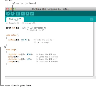
On your computer, go open the folder where you copied the Arduino IDE. Double-click the Arduino icon to start it. Select File > New and you’ll be asked to choose a sketch folder name: this is where your Arduino sketch will be stored. Name it Blinking_LED and click OK. Then, type the following text (Example 01) into the Arduino sketch editor (the main window of the Arduino IDE). You can also download it from www.makezine.com/ getstartedarduino. It should appear as shown in Figure 4-3.
// Example 01 : Blinking LED
const int LED = 13; // LED connected to // digital pin 13
void setup() {
pinMode(LED, OUTPUT); // sets the digital // pin as output }
void loop() {
Figure 4-3.
The Arduino IDE with your irst sketch loaded
Now that the code is in your IDE, you need to verify that it is correct. Press the “Verify” button (Figure 4-3 shows its location); if everything is correct, you’ll see the message “Done compiling” appear at the bottom of the Arduino IDE. This message means that the Arduino IDE has translated your sketch into an executable program that can be run by the board, a bit like an .exe ile in Windows or an .app ile on a Mac.
At this point, you can upload it into the board: press the Upload to I/O Verify
Upload to I/O board
You will see a few messages appear in the black area at the bottom of the window, and just above that area, you’ll see the message “Done upload-ing” appear to let you know the process has completed correctly. There are two LEDs, marked RX and TX, on the board; these lash every time a byte is sent or received by the board. During the upload process, they keep lickering.
If you don’t see the LEDs licker, or if you get an error message instead of “Done uploading”, then there is a communication problem between your computer and Arduino. Make sure you’ve selected the right serial port (see Chapter 3) in the Tools > Serial Port menu. Also, check the Tools > Board menu to conirm that the correct model of Arduino is selected there.
If you are still having problems, check Chapter 7, Troubleshooting.
Once the code is in your Arduino board, it will stay there until you put another sketch on it. The sketch will survive if the board is reset or turned off, a bit like the data on your computer’s hard drive.
Assuming that the sketch has been uploaded correctly, you will see the LED “L” turn on for a second and then turn off for a second. If you installed a separate LED as shown back in Figure 4-2, that LED will blink, too. What you have just written and run is a “computer program”, or sketch, as Arduino programs are called. Arduino, as I’ve mentioned before, is a small computer, and it can be programmed to do what you want. This is done using a programming language to type a series of instructions in the Arduino IDE, which turns it into an executable for your Arduino board.
I’ll next show you how to understand the sketch. First of all, the Arduino executes the code from top to bottom, so the irst line at the top is the irst one read; then it moves down, a bit like how the playhead of a video player like QuickTime Player or Windows Media Player moves from left to right showing where in the movie you are.
Pass Me the Parmesan
as our brain. So to group together a number of instructions, you stick a { before your code and an } after.
You can see that there are two blocks of code that are deined in this way here. Before each one of them there is a strange command:
void setup()
This line gives a name to a block of code. If you were to write a list of instructions that teach Arduino how to pass the Parmesan, you would write void passTheParmesan() at the beginning of a block, and this block would become an instruction that you can call from anywhere in the Arduino code. These blocks are called functions. If after this, you write passTheParmesan() anywhere in your code, Arduino will execute those instructions and continue where it left off.
Arduino Is Not for Quitters
Arduino expects two functions to exist—one called setup() and one called loop().
setup() is where you put all the code that you want to execute once at the beginning of your program and loop() contains the core of your program, which is executed over and over again. This is done because Arduino is not like your regular computer—it cannot run multiple programs at the same time and programs can’t quit. When you power up the board, the code runs; when you want to stop, you just turn it off.
Real Tinkerers Write Comments
Any text beginning with // is ignored by Arduino. These lines are comments, which are notes that you leave in the program for yourself, so that you can remember what you did when you wrote it, or for somebody else, so that they can understand your code.
The Code, Step by Step
At irst, you might consider this kind of explanation too unnecessary, a bit like when I was in school and I had to study Dante’s Divina Commedia (every Italian student has to go through that, as well as another book called I promessi sposi, or The Betrothed—oh, the nightmares). For each line of the poems, there were a hundred lines of commentary! However, the explanation will be much more useful here as you move on to writing your own programs.
// Example 01 : Blinking LED
A comment is a useful way for us to write little notes. The preceding title comment just reminds us that this program, Example 01, blinks an LED.
const int LED = 13; // LED connected to // digital pin 13
const int means that LED is an integer number that can’t be changed (i.e. a constant) whose value is set to 13. It’s like an automatic search and re-place for your code; in this case, it’s telling Arduino to write the number 13 every time the word LED appears. We are using this command to specify that the LED we’re blinking is connected to the Arduino pin 13.
void setup()
This line tells Arduino that the next block of code will be called setup().
{
With this opening curly bracket, a block of code begins.
pinMode(LED, OUTPUT); // sets the digital // pin as output
Finally, a really interesting instruction. pinMode tells Arduino how to con-igure a certain pin. Digital pins can be used either as INPUT or OUTPUT. In this case, we need an output pin to control our LED, so we place the number of the pin and its mode inside the parentheses.
pinMode is a function, and the words (or numbers) speciied inside the parentheses are arguments. INPUT and OUTPUT are constants in the Arduino language. (Like variables, constants are assigned values, except that constant values are predeined and never change.)
}
void loop() {
loop() is where you specify the main behaviour of your interactive device. It will be repeated over and over again until you switch the board off.
digitalWrite(LED, HIGH); // turns the LED on
As the comment says, digitalWrite() is able to turn on (or off) any pin that has been conigured as an OUTPUT. The irst argument (in this case, LED) speciies which pin should be turned on or off (remember that LED is a constant value that refers to pin 13, so this is the pin that’s switched). The second argument can turn the pin on (HIGH) or off (LOW).
Imagine that every output pin is a tiny power socket, like the ones you have on the walls of your apartment. European ones are 230 V, American ones are 110 V, and Arduino works at a more modest 5 V. The magic here is when software becomes hardware. When you write digitalWrite(LED, HIGH), it turns the output pin to 5 V, and if you connect an LED, it will light up. So at this point in your code, an instruction in software makes some-thing happen in the physical world by controlling the low of electricity to the pin. Turning on and off the pin at will now let us translate these into something more visible for a human being; the LED is our actuator.
delay(1000); // waits for a second
Arduino has a very basic structure. Therefore, if you want things to happen with a certain regularity, you tell it to sit quietly and do nothing until it is time to go to the next step. delay() basically makes the processor sit there and do nothing for the amount of milliseconds that you pass as an argument. Milliseconds are thousandths of seconds; therefore, 1000 milliseconds equals 1 second. So the LED stays on for one second here.
digitalWrite(LED, LOW); // turns the LED off
This instruction now turns off the LED that we previously turned on. Why do we use HIGH and LOW? Well, it’s an old convention in digital electronics. HIGH means that the pin is on, and in the case of Arduino, it will be set at 5 V. LOW means 0 V. You can also replace these arguments mentally with ON and OFF.
delay(1000); // waits for a second
To sum up, this program does this:
» Turns pin 13 into an output (just once at the beginning)
» Enters a loop
» Switches on the LED connected to pin 13
» Waits for a second
» Switches off the LED connected to pin 13
» Waits for a second
» Goes back to beginning of the loop
I hope that wasn’t too painful. You’ll learn more about how to program as you go through the later examples.
Before we move on to the next section, I want you to play with the code. For example, reduce the amount of delay, using different numbers for the on and off pulses so that you can see different blinking patterns. In particular, you should see what happens when you make the delays very small, but use different delays for on and off … there is a moment when something strange happens; this “something” will be very useful when you learn about pulse-width modulation later in this book.
What We Will Be Building
I have always been fascinated by light and the ability to control different light sources through technology. I have been lucky enough to work on some interesting projects that involve controlling light and making it interact with people. Arduino is really good at this. Throughout this book, we will be working on how to design “interactive lamps”, using Arduino as a way to learn the basics of how interactive devices are built.
What Is Electricity?
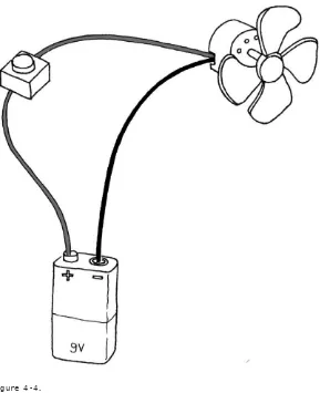
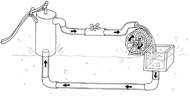
If you have done any plumbing at home, electronics won’t be a problem for you to understand. To understand how electricity and electric circuits work, the best way is to use something called the “water analogy”. Let’s take a simple device, like the battery-powered portable fan shown in Figure 4-4.
chill. How does this work? Well, imagine that the battery is both a water reservoir and a pump, the switch is a tap, and the motor is one of those wheels that you see in watermills. When you open the tap, water lows from the pump and pushes the wheel into motion.
In this simple hydraulic system, shown in Figure 4-5, two factors are important: the pressure of the water (this is determined by the power of pump) and the amount of water that will low in the pipes (this depends on the size of the pipes and the resistance that the wheel will provide to the stream of water hitting it).
Figure 4-5. A hydraulic system
the friction between the axle and the holes in which it is mounted in will generate heat. It is important to understand that in a system like this, not all the energy you pump into the system will be converted into movement; some will be lost in a number of ineficiencies and will generally show up as heat emanating from some parts of the system.
So what are the important parts of the system? The pressure produced by the pump is one; the resistance that the pipes and wheel offer to the low of water, and the actual low of water (let’s say that this is represented by the number of litres of water that low in one second) are the others. Electricity works a bit like water. You have a kind of pump (any source of electricity, like a battery or a wall plug) that pushes electric charges (imagine them as “drops” of electricity) down pipes, which are repre-sented by the wires—some devices are able to use these to produce heat (your grandma’s electric blanket), light (your bedroom lamp), sound (your stereo), movement (your fan), and much more.
So when you read that a battery’s voltage is 9 V, think of this voltage like the water pressure that can potentially be produced by this little “pump”. Voltage is measured in volts, named after Alessandro Volta, the inventor of the irst battery.
Just as water pressure has an electric equivalent, the low rate of water does, too. This is called current, and is measured in amperes (after André-Marie Ampère, electromagnetism pioneer). The relationship between voltage and current can be illustrated by returning to the water wheel: a higher voltage (pressure) lets you spin a wheel faster; a higher low rate (current) lets you spin a larger wheel.
Finally, the resistance opposing the low of current over any path that it travels is called—you guessed it—resistance, and is measured in ohms (after the German physicist Georg Ohm). Herr Ohm was also responsible for formulating the most important law in electricity—and the only formula that you really need to remember. He was able to demonstrate that in a circuit the voltage, the current, and the resistance are all related to each other, and in particular that the resistance of a circuit determines the amount of current that will low through it, given a certain voltage supply.
I close the valve—increasing resistance to water low—the less water will low through the pipes. Ohm summarised his law in these formulae:
R (resistance) = V (voltage) / I (current) V = R * I
I = V / R
This is the only rule that you really have to memorise and learn to use, because in most of your work, this is the only one that you will really need.
Using a Pushbutton to Control the LED
Blinking an LED was easy, but I don’t think you would stay sane if your desk lamp were to continuously blink while you were trying to read a book. Therefore, you need to learn how to control it. In our previous
example, the LED was our actuator, and our Arduino was controlling it. What is missing to complete the picture is a sensor.
In this case, we’re going to use the simplest form of sensor available: a pushbutton.
If you were to take apart a pushbutton, you would see that it is a very simple device: two bits of metal kept apart by a spring, and a plastic cap that when pressed brings the two bits of metal into contact. When the bits of metal are apart, there is no circulation of current in the pushbutton (a bit like when a water valve is closed); when we press it, we make a connection.
To monitor the state of a switch, there’s a new Arduino instruction that you’re going to learn: the digitalRead() function.
digitalRead() checks to see whether there is any voltage applied to the pin that you specify between parentheses, and returns a value of HIGH or LOW, depending on its indings. The other instructions that we’ve used so far haven’t returned any information—they just executed what we asked them to do. But that kind of function is a bit limited, because it will force us to stick with very predictable sequences of instructions, with no input from the outside world. With digitalRead(), we can “ask a question” of Arduino and receive an answer that can be stored in memory somewhere and used to make decisions immediately or later.
» Solderless breadboard: Maker Shed (
www.makershed.com) part num-ber MKKN3, Arduino Store (bit.ly/ArduinoStoreBreadBoard). Appendix A is an introduction to the solderless breadboard.» Pre-cut jumper wire kit: Maker Shed MKKN4, Arduino Store (included
with the breadboard)» One 10K Ohm resistor: Maker Shed JM691104 (100-pack), Arduino
Store (bit.ly/ArduinoStore10k, 10-pack)NOTE: instead of buying precut jumper wire, you can also buy 22 AWG solid-core hookup wire in small spools and cut and strip it using wire cutters and wire strippers.
Let’s have a look at the code that we’ll be using to control the LED with our pushbutton:
// Example 02: Turn on LED while the button is pressed
const int LED = 13; // the pin for the LED const int BUTTON = 7; // the input pin where the // pushbutton is connected
int val = 0; // val will be used to store the state // of the input pin
void setup() {
pinMode(LED, OUTPUT); // tell Arduino LED is an output pinMode(BUTTON, INPUT); // and BUTTON is an input }
void loop(){
val = digitalRead(BUTTON); // read input value and store it
// check whether the input is HIGH (button pressed) if (val == HIGH) {
digitalWrite(LED, HIGH); // turn LED ON } else {
digitalWrite(LED, LOW); }
}
In Arduino, select File > New (if you have another sketch open, you may want to save it irst). When Arduino asks you to name your new sketch folder, type PushButtonControl. Type the Example 02 code into Arduino (or download it from www.makezine.com/getstartedarduino and paste it into the Arduino IDE). If everything is correct, the LED will light up when you press the button.
How Does This Work?
The if statement is possibly the most important instruction in a program-ming language, because it allows the computer (and remember, the Arduino is a small computer) to make decisions. After the if keyword, you have to write a “question” inside parentheses, and if the “answer”, or result, is true, the irst block of code will be executed; otherwise, the block of code after else will be executed. Notice that I have used the == symbol instead of =. The former is used when two entities are compared, and returns TRUE or FALSE; the latter assigns a value to a variable. Make sure that you use the correct one, because it is very easy to make that mistake and use just =, in which case your program will never work. I know, because after 25 years of programming, I still make that mistake.
Holding your inger on the button for as long as you need light is not practical. Although it would make you think about how much energy you’re wasting when you walk away from a lamp that you left on, we need to igure out how to make the on button “stick”.
One Circuit, A Thousand Behaviours
The great advantage of digital, programmable electronics over classic electronics now becomes evident: I will show you how to implement many different “behaviours” using the same electronic circuit as in the previous section, just by changing the software.
As I’ve mentioned before, it’s not very practical to have to hold your inger on the button to have the light on. We therefore must implement some form of “memory”, in the form of a software mechanism that will remem-ber when we have pressed the button and will keep the light on even after we have released it.
A variable, as the name intimates, can be modiied anywhere in your code, so that later on in your program, you could write:
val = 112;
which reassigns a new value, 112, to your variable.
NOTE: Have you noticed that in Arduino, every instruction ends with a semicolon? This is done so that the compiler (the part of Arduino that turns your sketch into a program that the microcontroller can run) knows that your statement is inished and a new one is beginning. Remember to use it all the time.
In the following program, val is used to store the result of digitalRead(); whatever Arduino gets from the input ends up in the variable and will stay there until another line of code changes it. Notice that variables use a type of memory called RAM. It is quite fast, but when you turn off your board, all data stored in RAM is lost (which means that each variable is reset to its initial value when the board is powered up again). Your programs themselves are stored in lash memory—this is the same type used by your mobile phone to store phone numbers—which retains its content even when the board is off.
// Example 03A: Turn on LED when the button is pressed // and keep it on after it is released
const int LED = 13; // the pin for the LED const int BUTTON = 7; // the input pin where the // pushbutton is connected int val = 0; // val will be used to store the state // of the input pin
int state = 0; // 0 = LED off while 1 = LED on
void setup() {
pinMode(LED, OUTPUT); // tell Arduino LED is an output pinMode(BUTTON, INPUT); // and BUTTON is an input }
void loop() {
val = digitalRead(BUTTON); // read input value and store it
// check if the input is HIGH (button pressed) // and change the state
if (val == HIGH) { state = 1 - state; }
if (state == 1) {
digitalWrite(LED, HIGH); // turn LED ON } else {
digitalWrite(LED, LOW); }
}
Later, we read the current state of the button, and if it’s pressed (val == HIGH), we change state from 0 to 1, or vice versa. We do this using a small trick, as state can be only either 1 or 0. The trick I use involves a small mathematical expression based on the idea that 1 – 0 is 1 and 1 – 1 is 0:
state = 1 – state;
The line may not make much sense in mathematics, but it does in pro-gramming. The symbol = means “assign the result of what’s after me to the variable name before me”—in this case, the new value of state is as-signed the value of 1 minus the old value of state.
Later in the program, you can see that we use state to igure out whether the LED has to be on or off. As I mentioned, this leads to somewhat laky results.
The results are laky because of the way we read the button. Arduino is really fast; it executes its own internal instructions at a rate of 16 million per second—it could well be executing a few million lines of code per sec-ond. So this means that while your inger is pressing the button, Arduino might be reading the button’s position a few thousand times and chang-ing state accordingly. So the results end up being unpredictable; it might be off when you wanted it on, or vice versa. As even a broken clock is right twice a day, the program might show the correct behaviour every once in a while, but much of the time it will be wrong.
How do we ix this? Well, we need to detect the exact moment when the button is pressed—that is the only moment that we have to change state. The way I like to do it is to store the value of val before I read a new one; this allows me to compare the current position of the button with the previous one and change state only when the button becomes HIGH after being LOW.
// Example 03B: Turn on LED when the button is pressed // and keep it on after it is released
// Now with a new and improved formula!
const int LED = 13; // the pin for the LED const int BUTTON = 7; // the input pin where the // pushbutton is connected int val = 0; // val will be used to store the state // of the input pin
int old_val = 0; // this variable stores the previous // value of "val"
int state = 0; // 0 = LED off and 1 = LED on
void setup() {
pinMode(LED, OUTPUT); // tell Arduino LED is an output pinMode(BUTTON, INPUT); // and BUTTON is an input }
void loop(){
val = digitalRead(BUTTON); // read input value and store it // yum, fresh
// check if there was a transition if ((val == HIGH) && (old_val == LOW)){ state = 1 - state;
}
old_val = val; // val is now old, let's store it
if (state == 1) {
digitalWrite(LED, HIGH); // turn LED ON } else {
digitalWrite(LED, LOW); }
}
button, the two contacts come together and electricity can low. This sounds ine and simple, but in real life the connection is not that perfect, especially when the button is not completely pressed, and it generates some spurious signals called bouncing.
When the pushbutton is bouncing, the Arduino sees a very rapid sequence of on and off signals. There are many techniques developed to do de-bouncing, but in this simple piece of code I’ve noticed that it’s usually enough to add a 10- to 50-millisecond delay when the code detects a transition.
// Example 03C: Turn on LED when the button is pressed // and keep it on after it is released
// including simple de-bouncing
// Now with another new and improved formula!!
const int LED = 13; // the pin for the LED const int BUTTON = 7; // the input pin where the // pushbutton is connected int val = 0; // val will be used to store the state // of the input pin
int old_val = 0; // this variable stores the previous // value of "val"
int state = 0; // 0 = LED off and 1 = LED on
void setup() {
pinMode(LED, OUTPUT); // tell Arduino LED is an output pinMode(BUTTON, INPUT); // and BUTTON is an input }
void loop(){
val = digitalRead(BUTTON); // read input value and store it // yum, fresh
// check if there was a transition if ((val == HIGH) && (old_val == LOW)){ state = 1 - state;
delay(10); }
old_val = val; // val is now old, let's store it
if (state == 1) {
digitalWrite(LED, HIGH); // turn LED ON } else {
digitalWrite(LED, LOW); }
5
/
Advanced Input
and Output
What you have just learned in Chapter 4 are
the most elementary operations we can do in
Arduino: controlling digital output and reading
digital input. If Arduino were some sort of
human language, those would be two letters
of its alphabet. Considering that there are just
ive letters in this alphabet, you can see how
much more work we have to do before we can
write Arduino poetry.
Trying Out Other On/Off Sensors
Now that you’ve learned how to use a pushbutton, you should know that there are many other very basic sensors that work according to the same principle:
Switches
Just like a pushbutton, but doesn’t automatically change state when released
Thermostats
A switch that opens when the temperature reaches a set value
Magnetic switches (also known as “reed relays”)
Tilt switches
A simple electronic component that contains two contacts and a little metal ball (or a drop of mercury, but I don’t recommend using those) An example of a tilt switch is called a tilt sensor. Figure 5-1 shows the inside of a typical model. When the sensor is in its upright position, the ball bridges the two contacts, and this works just as if you had pressed a pushbutton. When you tilt this sensor, the ball moves, and the contact is opened, which is just as if you had released a pushbutton. Using this simple component, you can implement, for example, gestural interfaces that react when an object is moved or shaken (bit.ly/ArduinoStoreTiltSensor).
Figure 5-1.
You should now experiment by looking at all the possible devices that have two contacts that close, like the thermostat that sets a room’s tem-perature (use an old one that’s no longer connected), or just placing two contacts next to each other and dropping water onto them.
For example, by using the inal example from Chapter 4 and a PIR sensor, you could make your lamp respond to the presence of human beings, or you could use a tilt switch to build one that turns off when it’s tilted on one side.
Controlling Light with PWM
With the knowledge that you have so far gained, you could build an interactive lamp that can be controlled—and not just with a boring on/off switch, but maybe in a way that’s a bit more elegant. One of the limita-tions of the blinking LED examples that we have used so far is that you can turn the light only on and off. A fancy interactive lamp needs to be dimmable. To solve this problem, we can use a little trick that makes a lot of things such as TV or cinema possible: persistence of vision.
As I hinted after the irst example in Chapter 4, if you change the num-bers in the delay function until you don’t see the LED blinking any more, you will notice that the LED seems to be dimmed at 50% of its normal brightness. Now change the numbers so that the LED is on is one quarter of the time that it’s off. Run the sketch and you’ll see that the brightness is roughly 25%. This technique is called pulse width modulation (PWM), a fancy way of saying that if you blink the LED fast enough, you don’t see it blink any more, but you can change its brightness by changing the ratio between the on time and the off time. Figure 5-3 shows how this works.
This technique also works with devices other than an LED. For example, you can change the speed of a motor in the same way.
For example, writing analogWrite(9,128) will set the brightness of an LED con-nected to pin 9 to 50%. Why 128? analogWrite() expects a number between 0 and 255 as an argument, where 255 means full brightness and 0 means off.
NOTE: Having three channels is very good, because if you buy red, green, and blue LEDs, you can mix their lights and make light of any colour that you like!
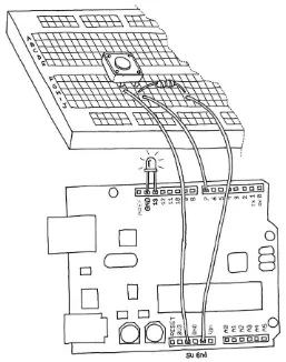
Let’s try it out. Build the circuit that you see in Figure 5-4. Note that LEDs are polarized: the long pin (positive) should go to the right, and the short pin (negative) to the left. Also, most LEDs have a lattened negative side, as shown in the igure. Use a 270 ohm resistor (red violet brown).
Figure 5-4.
Then, create a new sketch in Arduino and use Example 04 (you can also download code examples from www.makezine.com/getstartedarduino):
// Example 04: Fade an LED in and out like on // a sleeping Apple computer
const int LED = 9; // the pin for the LED
int i = 0; // We’ll use this to count up and down
void setup() {
pinMode(LED, OUTPUT); // tell Arduino LED is an output }
void loop(){
for (i = 0; i < 255; i++) { // loop from 0 to 254 (fade in) analogWrite(LED, i); // set the LED brightness delay(10); // Wait 10ms because analogWrite
// is instantaneous and we would // not see any change
}
for (i = 255; i > 0; i--) { // loop from 255 to 1 (fade out)
analogWrite(LED, i); // set the LED brightness delay(10); // Wait 10ms
}
}
Now you have a replicated a fancy feature of a laptop computer (maybe it’s a bit of a waste to use Arduino for something so simple). Let’s use this knowledge to improve our lamp.
To create this circuit, you will need to combine the circuit you just built (shown in Figure 5-4) with the pushbutton circuit shown in Figure 4-6. If you’d like, you can simply build both circuits on different parts of the breadboard; you have plenty of room. However, one of the advantages of the breadboard (see Appendix A) is that there is a pair of rails running horizontally across the bottom and top. One is marked red (for positive) and the other blue or black (for ground).
These rails are used to distribute power and ground to where it’s needed. In the case of the circuit you need to build for this example, you have two components (both of them resistors) that need to be connected to the GND (ground) pin on the Arduino. Because the Arduino has three GND pins, you could simply connect these two circuits exactly as shown in each of the two igures; just hook them both up to the Arduino at the same time. Or, you could connect one wire from the breadboard’s ground rail to one of the GND pins on the Arduino, and then take the wires that are connected to GND in the igures and connect them instead to the breadboard ground rail.
If you’re not ready to try this, don’t worry: simply wire up both circuits to your Arduino as shown in Figures 4-6 and 5-4. You’ll see an example that uses the ground and positive breadboard rails in Chapter 6.
Getting back to this next example, if we have just one pushbutton, how do we control the brightness of a lamp? We’re going to learn yet another interaction design technique: detecting how long a button has been pressed. To do this, I need to upgrade example 03C from Chapter 4 to add dimming. The idea is to build an “interface” in which a press and release action switches the light on and off, and a press and hold action changes brightness.
// Example 05: Turn on LED when the button is pressed // and keep it on after it is released
// including simple de-bouncing.
// If the button is held, brightness changes.
const int LED = 9; // the pin for the LED const int BUTTON = 7; // input pin of the pushbutton
int val = 0; // stores the state of the input pin
int old_val = 0; // stores the previous value of "val" int state = 0; // 0 = LED off while 1 = LED on
int brightness = 128; // Stores the brightness value unsigned long startTime = 0; // when did we begin pressing?
void setup() {
pinMode(LED, OUTPUT); // tell Arduino LED is an output pinMode(BUTTON, INPUT); // and BUTTON is an input }
void loop() {
val = digitalRead(BUTTON); // read input value and store it // yum, fresh
// check if there was a transition if ((val == HIGH) && (old_val == LOW)) {
state = 1 - state; // change the state from off to on // or vice-versa
startTime = millis(); // millis() is the Arduino clock // it returns how many milliseconds // have passed since the board has // been reset.
// check whether the button is being held down if ((val == HIGH) && (old_val == HIGH)) {
// If the button is held for more than 500ms. if (state == 1 && (millis() - startTime) > 500) {
brightness++; // increment brightness by 1 delay(10); // delay to avoid brightness going // up too fast
if (brightness > 255) { // 255 is the max brightness
brightness = 0; // if we go over 255 // let’s go back to 0 }
} }
old_val = val; // val is now old, let’s store it
if (state == 1) {
analogWrite(LED, brightness); // turn LED ON at the // current brightness level } else {
analogWrite(LED, 0); // turn LED OFF }
}
Now try it out. As you can see, our interaction model is taking shape. If you press the button and release it immediately, you switch the lamp on or off. If you hold the button down, the brightness changes; just let go when you have reached the desired brightness.
Now let’s learn how to use some more interesting sensors.
Figure 5-5.
Light-dependent resistor (LDR)
In darkness, the resistance of a light-dependent resistor (LDR) is quite high. When you shine some light at it, the resistance quickly drops and it becomes a reasonably good conductor of electricity. It is thus a kind of light-activated switch.
Build the circuit that came with Example 02 (see “Using a Pushbutton to Control the LED” in Chapter 4), then upload the code from Example 02 to your Arduino.
Analog Input
As you learned in the previous section, Arduino is able to detect whether there is a voltage applied to one of its pins and report it through the digitalRead() function. This kind of either/or response is ine in a lot of applications, but the light sensor that we just used is able to tell us not just whether there is light, but also how much light there is. This is the difference between an on/off sensor (which tells us whether something is there) and an analogue sensor, whose value continuously changes. In order to read this type of sensor, we need a different type of pin.
In the lower-right part of the Arduino board, you’ll see six pins marked “Analog In”; these are special pins that can tell us not only whether there is a voltage applied to them, but if so, also its value. By using the analogRead() function, we can read the voltage applied to one of the pins. This function returns a number between 0 and 1023, which represents voltages between 0 and 5 volts. For example, if there is a voltage of 2.5 V applied to pin number 0, analogRead(0) returns 512.
// Example 06A: Blink LED at a rate speciied by the // value of the analogue input
const int LED = 13; // the pin for the LED
int val = 0; // variable used to store the value // coming from the sensor
void setup() {
pinMode(LED, OUTPUT); // LED is as an OUTPUT
// Note: Analogue pins are // automatically set as inputs }
void loop() {
val = analogRead(0); // read the value from // the sensor
digitalWrite(LED, HIGH); // turn the LED on
delay(val); // stop the program for // some time
digitalWrite(LED, LOW); // turn the LED off
delay(val); // stop the program for // some time
}
// Example 06B: Set the brightness of LED to // a brightness speciied by the
// value of the analogue input
const int LED = 9; // the pin for the LED
int val = 0; // variable used to store the value // coming from the sensor
void setup() {
pinMode(LED, OUTPUT); // LED is as an OUTPUT
// Note: Analogue pins are // automatically set as inputs }
void loop() {
val = analogRead(0); // read the value from // the sensor
analogWrite(LED, val/4); // turn the LED on at // the brightness set // by the sensor
delay(10); // stop the program for // some time
}
NOTE: We specify the brightness by dividing val by 4, because analogRead() returns a number up to 1023, and analogWrite() accepts a maximum of 255.
Try Other Analogue Sensors
Using the same circuit that you have seen in the previous section, you can connect a lot of other resistive sensors that work in more or less the same way. For example, you could connect a thermistor, which is a simple device whose resistance changes with temperature. In the circuit, I have shown you how changes in resistance become changes in voltage that can be measured by Arduino.
If you do work with a thermistor, be aware that there isn’t a direct connec-tion between the value you read and the actual temperature measured. If you need an exact reading, you should read the numbers that come out of the analogue pin while measuring with a real thermometer. You could put these numbers side by side in a table and work out a way to calibrate the analogue results to real-world temperatures.
Until now, we have just used an LED as an output device, but how do we read the actual values that Arduino is reading from the sensor? We can’t make the board blink the values in Morse code (well, we could, but there is an easier way for humans to read the values). For this, we can have Arduino talk to a computer over a serial port, which is described in the next section.
Serial Communication
You learned at the beginning of this book that Arduino has a USB connec-tion that is used by the IDE to upload code into the processor. The good news is that this connection can also be used by the sketches that we write in Arduino to send data back to the computer or to receive commands from it. For this purpose, we are going to use a serial object (an object is a collection of capabilities that are bundled together for the convenience of people writing sketches).
// Example 07: Send to the computer the values read from // analogue input 0
// Make sure you click on "Serial Monitor" // after you upload
const int SENSOR = 0; // select the input pin for the // sensor resistor
int val = 0; // variable to store the value coming // from the sensor
void setup() {
Serial.begin(9600); // open the serial port to send // data back to the computer at // 9600 bits per second
}
void loop() {
val = analogRead(SENSOR); // read the value from // the sensor
Serial.println(val); // print the value to // the serial port
delay(100); // wait 100ms between // each send }